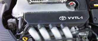
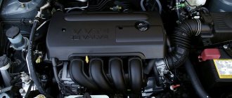
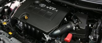
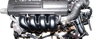
The Toyota ZZ engine family includes several power units ranging from 1.4 to 1.8 liters. These are rather ordinary engines that appeared in 1997. They are based on an aluminum block with thin-walled cast iron liners, have a timing chain drive, 16-valve cylinder heads without hydraulic compensators and a VVT variable valve timing system with a phase shifter on the intake camshaft.
This engine is made as lightweight as possible to improve its environmental performance. Pistons with shortened skirts in the side projection have a T-shaped profile, the camshaft cams are made thinner than those of their predecessor engines.
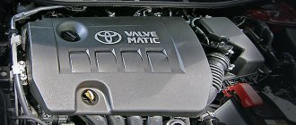
The 1ZZ-FE engine is very common; all popular European and purely Japanese Toyota models have it: Corolla, Celica, RAV4, MR2. It was installed on the Toyota Matrix and its clone Pontiac Vibe. The same engine was licensed to some Chinese manufacturers, for example, Geely under the label FE-1 and Lifan - LFB479Q.
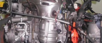
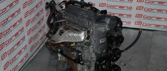
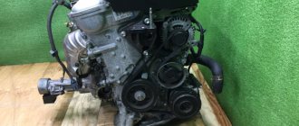
We will be disassembling an engine removed from a 2004 Toyota Avensis.
On our YouTube channel you can watch a disassembly of a 1.8-liter 1ZZ-FE engine removed from a 2004 Toyota Avensis.
You can select and buy an engine for Toyota in our catalog of contract engines.
VVTI clutch malfunction symptoms Toyota Corolla
The VVT-i valve causes a lot of problems for owners. Rubber rings, in its design, compress into a triangle over time and press the valve stem. The valve jams - the stem gets stuck in an arbitrary position. All this leads to oil (pressure) leaking into the VVT-i coupling. The clutch turns the camshaft. At the same time, the engine begins to stall at idle. Either the revs become very high or they float. Depending on the malfunction, the system records errors 18, P1346 (a timing violation is detected within 5 seconds); 59, P1349 (At a rotation speed of 500-4000 rpm and a coolant temperature of 80-110°, the valve timing differs from the required by ±5° for 5 or more seconds); 39, P1656 (valve - open or short circuit in the valve circuit of the VVT-i system for 1 or more seconds).
Below in the photographs are the valve installation location, catalog number, valve disassembly and examples of “triangular” rubber rings, date with changed vacuum due to the valve wedge. Example of a stuck valve stem and oil filter location.
Checking the system consists of testing the operation of the valve. The scanner provides a test to turn on the valve. When the valve is turned on at idle, the engine stalls. The valve itself is physically checked for sticking of the rod stroke. Replacing the valve is not particularly difficult. After replacement, you need to reset the battery terminal to bring the speed back to normal. Valve repair is also possible. You need to flare it and replace the O-ring. The main thing during repairs is to maintain the correct position of the valve stem. Before repairs, it is necessary to make control marks for installing the core in relation to the winding. You also need to clean the filter mesh in the VVT-i system.
VVTI is a variable valve timing system developed by Toyota. If we translate this abbreviation from English, then this system is responsible for intelligent phase shift. Now the second generation of mechanisms is installed on modern Japanese engines. And for the first time VVTI began to be installed on cars in 1996. The system consists of a coupling and a special VVTI valve. The latter acts as a sensor.
Weaknesses of the 2AZ-FE engine
- Balancing mechanism;
- Water pump;
- Cylinder block;
- Generator pulley overrunning clutch;
- Pistons and piston rings.
Weaknesses of the 2AZ-FE engine
Balancing mechanism
The gears of the balancing mechanism are made of polymers, so you can’t count on its durability.
Water pump
The water pump (pump) must be replaced after 50 - 60 thousand km, it fails.
Cylinder block
The problem is the same as on the 1AZ-FE engine. The threads in the holes for fastening the head are destroyed due to temperature loads.
Generator pulley overrunning clutch
The overrunning clutch of the generator pulley is also a weak point of the AZ series engines. It breaks down after about 100 thousand km.
Pistons and piston rings
The rings get stuck in the pistons, which significantly increases oil consumption. They are treated by replacing rings and pistons. Before solving problems with threads for mounting the head in the cylinder block (until 2007), there were no problems. In general, they changed the awl for soap, if not the thread, then the piston and rings.
Detailed job description
The main control mechanism of the system (this is the clutch) is installed on the engine camshaft pulley. Its housing is connected to the sprocket or the rotor is connected directly to the camshaft. Oil is supplied from one or both sides to each rotor lobe on the clutch, thereby causing the camshaft to turn. When the engine is not running, the system automatically sets the maximum retard angles. They correspond to the latest opening and closing of the intake valves. When the engine starts, the oil pressure is not strong enough to open the VVTI valve. To avoid any shocks in the system, the rotor is connected to the coupling body with a pin, which, as the lubricant pressure increases, will be pressed out by the oil itself.
The operation of the system is controlled by a special valve. Upon a signal from the ECU, an electric magnet using a plunger will begin to move the spool, thereby passing oil in one direction or the other. When the motor is stopped, this spool moves due to the spring so as to set the maximum delay angle. To rotate the camshaft to a certain angle, high-pressure oil is supplied through a spool to one side of the lobes on the rotor. At the same time, a special cavity opens for drainage. It is located on the other side of the petal. Once the ECU understands that the camshaft has been rotated to the desired angle, the pulley channels overlap and it will continue to be held in this position.
Principle of operation
The main element of the system's functioning is the coupling. The mechanism is designed to start work at low speeds, so the valves open, creating good traction.
After increasing the speed, the oil pressure sensor records the increased readings. This causes the VVT-i valve to open. When the valve opens, the camshaft rotates in relation to the pulley.
Cams of a certain shape at the moments when the crankshaft turns, the opening of the intake valves occurs earlier and the closing later. This has a positive effect on the power of the engine.
Design and operation of VVT-I.
VVT-I engine running at idle speed. At xx there is no need to develop more power. There is no need to open the intake valves - earlier, because the throttle valve is closed, the amount of air-fuel mixture in the intake manifold is minimal. Accordingly, the pressure in the intake manifold is low, i.e. The vacuum in the intake manifold is high. The condition in which the intake and exhaust valves are open is called valve overlap. In this condition, the high-pressure exhaust gases enter the low-pressure intake manifold. When this happens, the combustion process becomes unstable, causing the engine to run erratically. In conventional engines, in order to stabilize its operation, the speed is slightly increased. In an internal combustion engine with VVT-I, it delays the opening time of the intake valves to avoid valve overlap. Fuel consumption decreases in proportion to the decrease in rpm.
VVT-I engine operation in normal mode. Normal mode - the accelerator pedal is depressed no more than 1/2 of the way. Operation of the internal combustion engine under a slight load, driving at a constant speed, normal acceleration, driving on hilly terrain can also be classified as normal mode. Under such conditions, VVT-I shifts the phases towards advance to increase valve overlap. Valve overlap is now used effectively, despite the fact that it has a negative effect on the speed. Because in normal mode, the speed is quite high, a large power reserve is created, and the internal combustion engine operates stably. The resistance to piston movement during the intake stroke - upward movement - decreases due to valve overlap. Which leads to reduced fuel consumption. The penetration of exhaust gases into the intake manifold makes the exhaust cleaner. Unburned fuel, which is present in the exhaust gases, re-enters the combustion chamber. The temperature in the combustion chamber decreases due to afterburning of exhaust gases - which has a positive effect on the internal combustion engine.
VVT-I engine operation under load. The accelerator pedal is fully depressed. Driving at high speed, driving on mountain roads. In this case, maximum engine power is required. The operation of the VVT-I valve timing is similar to that in normal mode. But! When the driver fully depresses the accelerator pedal, at the initial moment, the engine speed is still low. In this case, the engine is pushed back into the intake manifold. As a result, the number of fuels in the cylinder decreases. Therefore, in order to increase the filling of the cylinders, the intake valves must close as early as possible. The valve overlap time increases. Because the throttle valve is open wide, the pressure in the intake manifold is close to atmospheric pressure - the vacuum in the intake valve is minimal. Therefore, the amount of exhaust gases flowing into the intake manifold is less than in normal mode or there is none at all. When the accelerator pedal is fully depressed, a quantity of fuel assemblies enters the cylinders - which is limited only by the capabilities of the engine.
VVT-I device. The VVT-i mechanism is controlled electronically. The crankshaft position sensor and camshaft position sensor determine the position of the piston. To determine the load on the engine, an air flow meter and a throttle position sensor are used. The signal from the coolant temperature sensor determines the temperature conditions of the engine. Information from these sensors is sent to the electronic control unit, which calculates the optimal opening time of the intake valves. The computer then sends a signal to the VVT-i oil control valve. The VVT-i control valve switches the supply of oil under pressure to the working cavities of the intake camshaft gears. The gears do not have a rigid connection with the camshaft. The valve timing is changed by hydraulic oil pressure.
The ECU uses three types of signal: Initial stage, when the throttle valve is fully open, fixed - when the internal combustion engine has gained power. And when the valve is completely closed, while oil is supplied through different channels, the supply direction changes to the opposite.
VVT-I service. The VVT-i mechanism has a self-diagnosis function. If there is a malfunction, the Check Engine indicator always lights up. “Check Engine” is literally translated as “check the engine.” If there is no Jackie Chan, the computer still remembers all VVT-i faults in the form of a diagnostic code. (Code 59).
- We check the timing belt phases. Set the piston of the first cylinder to TDC on the compression stroke. Then we check whether the camshaft timing marks are aligned. If the marks do not align, it is necessary to adjust the timing phases. If the marks are aligned, go to step 2.
- Checking the VVT-i control valve. We start the engine and warm it up to operating temperature. We connect the TOYOTA tester, change the timing phases - while noting the engine speed. If the engine runs normally when the control valve is turned off, but the speed becomes unstable, or the engine stalls when the control valve is turned on, then the VVT-i mechanism is working normally. You need to look for the cause of the problem elsewhere. If the VVT-i control valve is not functioning properly you should check the engine computer. We connect the oscilloscope to the OCV + OCV contacts of the computer. We increase the engine speed, the duration of the signals should increase with increasing speed. If the shape of the control signals is abnormal, the ECU must be checked or replaced. The test procedure without a tester is given in the manuals of the corresponding models. If the signal shape is normal, proceed to step 3
- We check the oil channels of the VVT-i valve. We take out the valve - we wash the channels from the gear to the valve and the valve itself.
What happens when there is a break or short circuit in the control circuit, or the oil is squeezed out from under the valve. In this case the valve is turned off. The valve timing is fixed at the latest position. In this case, there will be a drop in power if you press the accelerator pedal all the way. In addition, the valve timing is fixed in the latest position after the engine is turned off and at the time of its start. Makes it easier to start the engine.
CAUTION: VVT-i gears must be replaced as an assembly.
Valve part number: 15330-21011
Engine operating modes
When idling, it is important that the system operates reliably even at the lowest speeds. In low speed mode the pressure and speed will be low.
At low pressure, gases will partially flow to the intake manifold, but engine instability is leveled out due to speed.
As a result, the exhaust gases will circulate and partially enter the intake valve, where they burn out in the combustion chamber. This reduces fuel consumption and improves exhaust purity.
At full load the pressure must reach or exceed atmospheric pressure.
When the valves close, exhaust gases will not enter the intake. Accordingly, their kinetic energy will increase as the speed increases.
This improves the efficiency of blowing and compaction. When the engine warms up and is running at low speeds under maximum load, the valve closes as wide an area as possible.
Otherwise, overpurge may occur. As the speed increases, the intake valves need to close later.
In the middle of this process, when the engine reaches 3500-4200 rpm, there comes a point when the purge and compaction time reaches its optimal value. At this moment, the maximum filling of the cylinder occurs.
After reaching the maximum filling point, the last phase begins when the engine runs at full load at high speeds. At this time, the filling rate will begin to decrease and shift the shaft to a later closure.
This increases the press-in period and ensures efficient engine operation while reducing filling rates.
Typical symptoms of VVTI system problems
So, the system must change the phases of operation. If any problems arise with it, then the car will not be able to function normally in one or more operating modes. There are several symptoms that indicate a malfunction.
So, the car does not keep idle speed at the same level. This indicates that the VVTI valve is not working as it should. Also, the “braking” of the engine will indicate various problems in the system. Often, if there are problems with this phase change mechanism, the motor is not able to operate at low speeds. Error P1349 may also indicate problems with the valve. If the idle speed is high when the power unit is warm, the car does not move at all.
What is Dual VVT i and VVT iE
Dual VVT-i is considered a popular gas distribution system in cars. Functions the same as on VVT-i, but it is a standard dual VVT-i system where the clutches are attached to the camshaft pulley. The system helps achieve greater fuel efficiency at any speed. Motors for such a system must be more flexible.
VVT-iE is also a variation of gas distribution systems, but its operation uses an electric motor. The operating principle is similar to VVTL-i, but the camshafts can be deflected at certain angles in order to advance or delay the reduction in oil pressure. This happens thanks to an electric motor. The system will not depend on engine speed and temperature conditions. When operating at low speeds, there is not enough pressure to move the clutch. Its operation is considered highly environmentally friendly and helps new generation engines achieve maximum power and operate the vehicle efficiently.
Possible causes of valve failure
There are not many main causes of valve failure. There are two that are particularly common. So, the VVTI valve may fail due to breaks in the coil. In this case, the element will not be able to respond correctly to voltage transfers. Diagnosis of the malfunction is easily carried out by checking the resistance measurement of the sensor coil winding.
The second reason why the VVTI (Toyota) valve does not work correctly or does not work at all is jamming in the stem. The cause of such jamming may be simple dirt that has accumulated in the channel over time. It is also possible that the sealing rubber inside the valve is deformed. In this case, restoring the mechanism is very simple - just clean the dirt from there. This can be done by soaking or soaking the element in special liquids.
Injectors
The injectors of the 1ZZ-FE engine are quite durable, that is, they rarely clog or fail. But if misfires occur in the cylinders, and there are no questions about the spark plugs and coils, then it’s worth washing these injectors or cleaning them with ultrasound. A cylinder with an injector that does not spray fuel sufficiently will also be indicated by a white coating on the spark plug electrodes - this is a sign of a poor air-fuel mixture. If all the spark plugs turn out to have a uniform white coating, then it is worth checking the fuel pump - it is possible that its fuel intake screen is very clogged.
Let's return to the injectors. When washing them, it is worth changing the filter meshes: they are removed from above, then you can pick them up in spare parts stores. Bosch injectors for VAZ cars have suitable meshes. The injectors should be installed on new sealing rings, which are located on the bottom and top of each nozzle.
You can select and buy gasoline injectors and a fuel rail for a Toyota engine in our catalog of contract spare parts.
How to clean the valve?
Many problems can be cured by cleaning the sensor. First you need to find the VVTI valve. Where this element is located can be seen in the photo below. It is circled in the picture.
Cleaning can be done using carburetor cleaning fluids. To completely clean the system, remove the filter. This element is located under the valve - it is a plug in which there is a hole for a hexagon. The filter also needs to be cleaned with this liquid. After all the operations, all that remains is to assemble everything in the reverse order, and then install it without resting against the valve itself.
Timing chain stretch
As already mentioned, the chain on the 1ZZ-FE engine is not durable. It can stretch and begin to rattle both at a mileage of 150,000 km and at twice that level. You can assess the condition of the timing chain after removing the chain: there should be no lateral play in it and, moreover, the chain should not be loose or sagging.
The chain tensioner has a ratchet stopper, which in no case allows the chain to come loose.
How to check the VVTI valve?
Checking whether the valve is working is very simple. To do this, a voltage of 12 V is applied to the sensor contacts. It must be remembered that it is impossible to keep the element under voltage for a long time, since it cannot operate in such modes for so long. When voltage is applied, the rod will retract inward. And when the circuit opens, he will come back.
If the stem moves easily, then the valve is fully operational. It only needs to be washed, lubricated and can be used. If it does not work as it should, then repairing or replacing the VVTI valve will help.
Do-it-yourself valve repair
First, remove the generator control bar. Then remove the hood lock fasteners. This will give access to the generator axle bolt. Next, unscrew the bolt that holds the valve itself and remove it. Then remove the filter. If the last element and valve are dirty, then these parts are cleaned. Repair consists of inspection and lubrication. You can also replace the O-ring. More serious repairs are not possible. If a part doesn't work, it's easier and cheaper to replace it with a new one.
Replacing 1NZ-FE engine mounts on a Toyota Funcargo
The presented report with photographs shows the labor-intensive process of car repair - changing the engine support, which is also called the “pillow”. We will show the process using the example of a Toyota Funcargo.
To change a broken or torn support, you will need the following items for work:
- a set of heads, of which you will need for 10.2 by 14 one simple and long one, for seventeen;
- collar;
- extension cords;
- key for twenty-two;
- wood lining;
- jack;
- hammer;
- stand;
- two flat screwdrivers, 1 small narrow one and an elongated narrow one;
- chisel;
The image shows a torn engine mount.
Before changing the engine mounts, it was necessary to change the gaskets in the middle of the exhaust manifold and muffler. But our problem lies elsewhere - in bent and stuck bolts.
Therefore, we decided that before changing the rear support we need to loosen these bolts. To be brief, the bolts need to be wrapped in a cloth, filled with WD-40 and left to soak for a day. Afterwards, when the engine is cold, in the pit using a strong fourteen socket, an extension and a long 65 cm wrench, first slightly twisting it to the side, then vice versa.
The front of the car needs to be lifted and placed on supports (a log will do). You only need to remove the wheel on the left side.
Remove the lambda probe using a twenty-two key.
Disconnect the sensor from the muffler pipe and the electrical connector by pushing the lever on the connector with an elongated thin screwdriver.
Disconnect the electrical connector from the fastening element on the rear support.
Use a short, thin, flat screwdriver to pry off the lever.
Use a screwdriver to disconnect the latch with the wiring of the lambda probe sensor connector from the support at the rear.
Let's try to break the bolt that holds the engine bracket to the support. You will need a fourteen head, a couple of extensions and a knob. The threads of this bolt should be cleaned and dipped in a WD-40 solution. It is not necessary to hold the nut on the opposite side with a wrench; it has a sidewall “whisker” that keeps it from turning.
It is good to unscrew this bolt from the side of the wheel on the left side.
A key with a strong head that you can build yourself will help you do this job. The longer the better.
This bolt needs to be removed by turning it slightly, but not completely unscrewing it.
Then unscrew the 2 nuts that hold the support bolts using a fourteen socket and a wrench.
The thread of this bolt also needs to be treated with WD. Using a hammer, carefully knock out these bolts.
So why do we need to knock out these bolts? You can't remove the pillow with them; they get in the way because of their length. The bolts are attached to splines in the engine support.
If a problem arises with the bolts, use a chisel, placing its sharp edge in the middle of the bolt head and the steel base of the support mount.
Then we place a jack at the bottom of the rib where the engine connects and lift it slightly. The jack also remains, at this time put supports under the engine. Place it with the lifting handle on the side of the wheels at the back so that later, when you climb under the car, you can raise or lower the engine using a jack.
Then completely unscrew the bolt that holds the engine bracket to the support. Unscrew the remaining bolt holding the support using a 14mm socket and a wrench. The bolt will be a little tight, so play with a jack and level the holes in the engine bracket and support.
This is a bolt holding the engine bracket to the support, and a nut.
What will happen to her when she moves.
You will immediately see gaps in it.
Let's compare the old one and the new one. Knock out the bolts from the new one (pry them out using a chisel and a screwdriver by the heads so as not to damage the threads).
Install a new support. If the hole in the engine bracket and the new support do not meet, lift the engine, insert the bolt and tighten it by hand. After tightening the support at the bottom with a bolt and inserting the remaining bolts at the top, try to match the splines while turning and tighten the nuts. Tighten the nuts and bolt securing the supports and the bolt securing the engine bracket to the support using a torque of 80 Nm. Remove the jack.
Then replace the support on the right. Secure the part of the engine on the right with a jack.
The support on the right is secured with 3 bolts to the side member of the car, and 2 bolts and 1 nut to the bracket on the right of the engine.
It should be noted that the nut must be screwed onto a stud located on the support and on the opposite side of the engine support bracket. It should be unscrewed at the bottom.
For unscrewing, the longest head of fourteen and a pair of extensions with a knob are used. Unscrew the remaining bolts using a 14mm socket, a rod and a knob.
After unscrewing the nuts and bolts, look at the support.
Do-it-yourself VVTI valve replacement
Often cleaning and lubrication do not provide the required result, and then the question arises of completely replacing the part. In addition, after replacement, many car owners claim that the car began to work much better and fuel consumption decreased.
First, remove the generator control bar. Then remove the fasteners and gain access to the generator bolt. Unscrew the bolt that holds the desired valve. The old element can be pulled out and thrown away, and a new one can be put in place of the old one. Then the bolt is tightened and the car can be driven.