A knock detection sensor (DS) in the engine cylinders was not an obvious need in the first engine control systems, and in the days of simpler principles of power management and ignition of gasoline internal combustion engines, abnormal combustion of the mixture was not monitored at all. But then the engines became more complex, the requirements for efficiency and exhaust purity increased sharply, which required an increase in the amount of control over their operation at each time.
Lean and ultra-lean mixtures, exorbitant compression ratios and other similar factors require constant work on the verge of detonation without going beyond this threshold.
Where is the knock sensor located and what does it affect?
Typically, the DD is installed on a threaded mount to the cylinder block, near the central cylinder closer to the combustion chambers. Its location is determined by the tasks it is called upon to perform.
Roughly speaking, a knock sensor is a microphone that picks up very specific sounds produced by a detonation wave hitting the walls of the combustion chambers.
This wave itself becomes the result of anomalous combustion in the cylinders at a very high speed. The difference between the standard process and the detonation process is the same as during the operation of a propelling powder charge in an artillery gun and a high explosive with which a projectile or grenade is filled.
The gunpowder burns slowly and pushes, and the contents of the landmine crush and destroy. The difference in the speed of propagation of the combustion boundary. During detonation it is many times higher.
In order not to damage engine parts, the occurrence of detonation must be noticed and stopped in time. Once upon a time, it was possible to afford the cost of excessive fuel consumption and environmental pollution in order to avoid detonation of the mixture in principle.
Gradually, motor technology reached such a level that all reserves were exhausted. It was necessary to force the engine to independently extinguish the resulting detonation. And an acoustic control “ear” was attached to the engine, which became the knock sensor.
Causes of detonation?
Probably, many car owners know first-hand what the concept of “fingers tapping” means. Some consider bad fuel to be the reason for this and decide to make the ignition later. But you shouldn’t make hasty conclusions; first of all, you need to figure out what exactly was knocking there and what the reason was.
In order to clearly understand the whole picture, you need to know what a combustion chamber is.
The chamber is the space in the cylinder head where combustible fuel is converted into mechanical work. The mixture of air and fuel is compressed during the upward stroke of the piston and at a certain moment it is ignited by an electric spark. This process is called ignition timing.
There is such a thing as ignition timing, which is measured in degrees. It shows the advance of the moment the spark occurs and the time the pistons reach the top point. This value largely depends on the quality of gasoline and other parameters. If the fuel is correctly selected and the mixture is correctly distributed, the flame spreads at the moment of combustion at approximately a speed of up to 30 m/sec. With this type of work, maximum use of the working mixture is achieved. It is worth noting that when using different types of gasoline on the same engine, it is necessary to adjust the ignition timing.
For example, the engine is adjusted to fuel with an octane rating of 95, but it started working with fuel whose octane rating is significantly lower. What happens at this moment? The working mixture begins to ignite much earlier, and the moment of reaching maximum energy also occurs much earlier than the piston itself reaches TDC; the pressure in the chamber begins to increase, resulting in an increase in temperature. At this moment, the fuel begins to ignite. Everything that happens is recorded by the engine knock sensor.
Types of sensors
According to the spectral characteristics, historically there are two of them - resonant and broadband .
In the first, a pronounced reaction to very specific sound frequencies is used to increase sensitivity. It is known in advance what spectrum is produced by the parts suffering from the shock wave; it is for them that the sensor is structurally adjusted.
Related article: Replacing the front strut support bearing with and without removing the shock absorber
A broadband type sensor has less sensitivity, but it detects vibrations of different frequencies. This allows you to unify the devices and not have to select their characteristics for a specific engine, and the greater ability to pick up weak signals is not in great demand; detonation has sufficient acoustic volume.
A comparison of both types of sensors led to the complete displacement of resonant DDs. Currently, only two-contact broadband toroidal sensors are used, secured to the block with a central pin and nut.
Why is a working knock sensor so important?
The knock sensor, if it malfunctions, cannot block engine operation, so sooner or later the question arises: what does the knock sensor affect? If the operability of the propulsion system is maintained, why does the engine need a knock sensor?
The malfunction makes the motor operation unoptimized. To ensure high efficiency and economy of the engine, its main operating mode is selected in the range of minimum mixture enrichment, with a maximum ignition angle. These most favorable conditions border on the regime of occurrence and development of detonation combustion. Thanks to detonation control, it is possible to get as close as possible to the point beyond which effective fuel combustion will turn into detonation combustion, with rapid failure of the engine pistons and rings. The most economical mixture is the one that burns with little sign of detonation. Catching detonation with a sensor allows you to finely balance the composition of the fuel mixture.
According to the principle of operation, the knock sensor is identical to a conventional piezoelectric microphone, tuned to a certain frequency of sound vibrations, characteristic only of detonation. There are many parts in a running engine that make noise at a specific natural frequency. To eliminate erroneous reactions to “foreign” sounds, the sensor, like a tuning fork, is tuned to a specific detonation sound wavelength. A sign of detonation is a sound with a frequency of 25-75 Hz. Other sounds may indicate a malfunction of the fingers or pistons of the internal combustion engine liners. Powerful “metallic” knocks that occur at the first signs of detonation of the air-gasoline mixture, spreading through the aluminum engine block, reach the piezoelectric crystal mounted in the housing and cause it to resonate in unison and generate a weak electrical potential at the contacts.
How a knock sensor works - receiving a signal of a carrier frequency and a certain level from the ECU, the device practically does not change it, thereby confirming its serviceability. When the piezoelectric crystal is triggered, the signal level and frequency increase, which gives the microcomputer reasons to change the operating parameters of the internal combustion engine. In this case, the intensity of the signal at the contacts is directly proportional to the strength of sound vibrations.
By design, there are two main types of knock sensors: broadband and resonant.
The first type perceives several basic signal frequencies, according to which it produces a certain level and frequency of the signal for the ECU. The second type is tuned to a certain specific frequency and produces only if it coincides or resonates with sound waves generated by detonation in the burning mixture.
Good day, dear readers! In the article we will analyze which sensors are responsible for what in diesel and gasoline engines, as well as characteristic signs of their incorrect operation. Remember that before you go to the service station and panic, you should spend a little time and try to find the cause of the malfunction yourself and fix it.
In most cases, the problem can be detected by having a personal diagnostic scanner with you. Today, these devices can not only indicate the location of the problem, but also describe in detail what happened. Among the currently available auto scanners, we can recommend Scan Tool Pro Black Edition.
The main advantages of this particular model include diagnostics of not only the engine, but also other vehicle systems. The scanner is quite easy to use, compatible with most new and old cars and has a wide range of functionality.
Signs of a malfunction of the TPS sensor
— high speeds are possible at idle, this is the most characteristic sign; — a noticeable decrease in engine power and deterioration in throttle response; — when you press the accelerator, jerks, dips and twitches appear; — floating speed at idle; — when changing gears, the engine stalls spontaneously; — engine overheating is possible; — when accelerating, detonation is observed.
(personally, my symptoms were high speeds, inability to brake with the engine, jerking when releasing the gas pedal, decreased power and, accordingly, increased gasoline consumption).
The photo shows very worn tracks
The reasons for the malfunction of the TPS sensor can be: - oxidation of the contacts, in this situation you need to take a special WD fluid and clean all the contacts in the block and under the cover with a lint-free cloth; — worn-out sensor substrates, if their design included sputtering of a resistive layer, in this situation we take tweezers and carefully, just a little bit, bend the contacts onto entire tracks; — the moving contact fails, some tip of this contact may break, then scoring will form and other tips will also fail; — the throttle valve does not close completely at idle, in this case you can slightly file the sensor seats and the throttle valve should close.
The speed sensor rarely fails
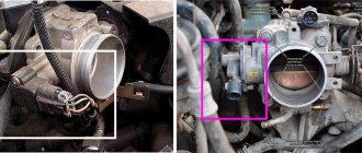
, the average car owner will not be able to diagnose the breakdown, some do not even know where the sensor itself is located, it is located opposite the throttle valve.
The check error does not always appear.
We recommend an article about repairing the TPS; it discusses one of the ways to restore its functionality.
Signs of a malfunctioning idle air valve
— unstable engine speed at idle; — spontaneous increase or decrease in engine speed; — the engine stalls when shifting gears or idling; — no increased speed when starting a cold engine; — reduction in engine idle speed when the load is turned on (headlights, stove, etc.).
The idle control valve will not be able to function normally in this state.
The check error does not always appear.
The best prevention is considered
periodic cleaning of the idle air valve with removal, usually done in the fall and spring. The valve is located near the throttle valve.
Signs of a malfunction of the mass air flow sensor
The MAF sensor can be called a mass air flow sensor, MAP or maf sensor.
Signs of a malfunction of the air flow sensor or absolute pressure in the intake manifold are characterized by: - up to 70 degrees the car works more or less well, after 70 an unstable idle begins; — failures during acceleration and adjustments; — the car sometimes stalls at idle when the gas pedal is sharply pressed; — increased consumption; — unpleasant exhaust smell; — popping noises in the muffler during operation and sometimes popping noises in the intake manifold. (incorrect ignition timing due to faulty sensor).
The air flow sensor is very sensitive and it is not recommended to clean it yourself; the more often you change the filter, the longer it will last you.
Symptoms of a problem
During normal engine operation, the knock sensor does not produce danger signals and does not participate in the operation of the control system in any way. The ECU program performs all actions according to its data cards hardwired into memory; standard modes ensure knock-free combustion of the air-fuel mixture.
But with significant temperature deviations in the combustion chambers, detonation may occur. The task of the DD is to give a signal in time to parry the danger. If this does not happen, then characteristic sounds are heard from under the hood, which for some reason drivers call finger tapping.
Although in fact no fingers are knocking, and the main level of volume comes from the vibration of the piston bottom, which is hit by a wave of explosive combustion. This is the main sign of abnormal operation of the knock control subsystem.
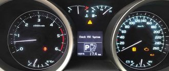
Indirect signs will be a noticeable loss of engine power, an increase in its temperature, up to the appearance of glow ignition, and the inability of the ECU to cope with the situation in normal mode. The reaction of the control program in such cases will be to light up the “Check Engine” light.
Typically, the ECU directly monitors the activity of the knock sensor. Its signal levels are known and stored in memory. The system compares the current information with the tolerance range and, when deviations are detected, simultaneously with the display turning on, it remembers error codes.
This is interesting: Checking diesel engine injectors and ways to clean them at home
These are various types of exceeding or decreasing the levels of the DD signal, as well as a complete break in its circuit. Error codes can be read from the on-board computer or an external scanner via the diagnostic connector.
Error codes can be read from the on-board computer or an external scanner via the diagnostic connector.
If you don’t have a diagnostic device, we recommend paying attention to the budget multi-brand auto scanner Scan Tool Pro Black Edition
.
A special feature of this Korean-made model is the diagnostics of not only the engine, as in most budget Chinese models, but also other components and assemblies of the car (gearbox, ABS auxiliary systems, transmission, ESP, etc.).
Also, this device is compatible with most cars starting from 1993, works stably without loss of communication with all popular diagnostic programs and has a fairly affordable price.
Toyota Corolla engine management system, replacement of coils, spark plugs, sensors
The engines installed on Toyota Corolla cars are equipped with an electronic engine management system with distributed fuel injection. This system ensures compliance with modern emission and evaporation standards while maintaining high driving performance and low fuel consumption.
The control device in the system is the electronic control unit (ECU). Based on the information received from the sensors, the ECU calculates the parameters for regulating fuel injection and controlling the ignition timing. In addition, in accordance with the established algorithm, the ECU controls the operation of the electric motors of the engine cooling system fan and the electromagnetic clutch for turning on the air conditioning compressor, performs the function of self-diagnosis of system elements and notifies the driver of any malfunctions that have arisen.
If individual sensors and actuators fail, the ECU turns on emergency modes to ensure engine operation.
The amount of fuel supplied by the injectors is determined by the duration of the electrical signal from the ECU. The electronic unit monitors data on the engine condition, calculates the fuel requirement and determines the required duration of fuel supply by the injectors (signal duration). To increase the amount of fuel supplied, the signal duration increases, and to decrease the fuel supply, it decreases.
The engine control system, along with the electronic control unit, includes sensors, actuators, connectors and fuses.
Electronic control unit
(controller) is connected by electrical wires to all sensors of the system. Receiving information from them, the unit performs calculations in accordance with the parameters and control algorithm stored in the memory of the programmable read-only memory (PROM) and controls the system's actuators. The program version recorded in the PROM memory is indicated by the number assigned to this ECU modification
The control unit detects a fault, identifies and stores its code, even if the fault is unstable and disappears (for example, due to poor contact). The engine management system malfunction indicator in the instrument cluster goes out after three ignition on/off cycles after the failed unit has been restored to functionality.
After repair, the fault code stored in the control unit's memory must be erased. To do this, turn off the power supply to the unit for 1 minute (remove the fuse for the power supply circuit of the electronic control unit or disconnect the wire from the negative terminal of the battery).
The unit supplies 5 and 12 V direct current to various sensors and switches of the control system. Since the electrical resistance of the power circuits is high, the test lamp connected to the system terminals does not light up. To determine the supply voltage at the ECU terminals, use a voltmeter with an internal resistance of at least 10 MOhm.
The ECU is not suitable for repair; if it fails, it must be replaced.
The inductive type crankshaft position sensor is designed to synchronize the operation of the electronic control unit with the TDC of the pistons of the 1st and 4th cylinders and the angular position of the crankshaft.
The sensor is installed at the front of the engine opposite the drive disc on the engine crankshaft. The drive disk is a toothed wheel with cavities. Two teeth are cut to create a synchronization pulse (“reference” pulse), which is necessary to coordinate the operation of the control unit with the TDC of the pistons in the 1st and 4th cylinders.
As the crankshaft rotates, the teeth change the sensor's magnetic field, inducing pulses of alternating current voltage. The control unit uses sensor signals to determine the crankshaft rotation speed and send pulses to the injectors.
If the sensor fails, starting the engine is impossible.
Inductive type phase sensors are installed in the upper left part of the cylinder head. As the camshaft rotates, the protrusion of its drive disc changes the sensor's magnetic field, inducing alternating current voltage pulses. The sensor signals are used by the controller to organize phased fuel injection in accordance with the operating order of the cylinders, as well as to control the change in valve timing depending on the engine operating mode. If a malfunction occurs in the camshaft position sensor circuit, the controller stores its code in its memory and turns on the alarm.
The coolant temperature sensor is installed in the engine cooling system. The sensitive element of the sensor is a thermistor, the electrical resistance of which varies inversely with temperature. At a low coolant temperature (-20 'C), the thermistor resistance is 15-30 kOhm; when the temperature rises to +80 'C, it decreases to 320 Ohm.
How to check the knock sensor
Knowing the design and principle of operation of the motor, you can check it in fairly simple ways, both by removing it from the engine and locally, including directly with the engine running.
Voltage measurement
A multimeter is connected to the sensor removed from the cylinder block in voltage measurement mode. By carefully bending the DD body through a screwdriver inserted into the hole in the sleeve, you can monitor the reaction of the built-in piezoelectric crystal to the deforming force.
Note: How to cover a steering wheel with braid: types and methods of lacing
The appearance of voltage at the connector and its value of the order of two to three tens of millivolts approximately indicates the serviceability of the device’s piezoelectric generator and its ability to generate a signal in response to mechanical stress.
Resistance measurement
Some sensors contain a built-in resistor connected as a shunt. Its value is on the order of tens or hundreds of kOhms. An open or short circuit in the circuit inside the case can be detected by connecting the same multimeter in resistance measurement mode.
The device must show the value of the shunt resistor, since the piezoelectric crystal itself has an almost infinitely large resistance that cannot be measured with a conventional multimeter. In this case, the readings of the device will also depend on the mechanical impact on the crystal due to the generation of voltage that distorts the ohmmeter readings.
Checking the sensor on the ECU connector
Having determined the required contact of the ECU controller connector from the electrical diagram of the car, the condition of the sensor can be checked more completely, with the inclusion of the supply wiring circuits.
The same measurements as described above are carried out on the removed connector; the only difference will be a simultaneous check of the cable’s serviceability. By bending and tugging the wires, they make sure that there is no stray fault, when contact appears and disappears due to mechanical vibrations. Corroding places where wires are inserted into connector tips are especially affected by this.
On topic: Checking gasoline injectors from A to Z
With the ECU connected and the ignition on, you can check the presence of a reference voltage at the sensor and the correctness of its division by external and built-in resistors, if this is provided for by the circuit of a particular vehicle.
Typically, the +5 Volt support is divided approximately in half and an alternating signal is generated against the background of this constant component.
Checking with an oscilloscope
The most accurate and complete instrument method will require the use of an automotive digital storage oscilloscope or an oscilloscope attachment to a diagnostic computer.
When hitting the DD body, the screen will show how capable the piezoelement is of generating steep fronts of the detonation signal, whether the seismic mass of the sensor works correctly, preventing extraneous damped oscillations, and whether the amplitude of the output signal is sufficient.
The technique requires sufficient experience in diagnostics and knowledge of typical signal pictures of a working device.
Checking on a running engine
The simplest test method does not even require the use of electrical measuring instruments. The engine starts and reaches below average speed. When applying moderate blows to the knock sensor, you can observe the reaction of the ECU to the appearance of its signals.
There should be a normal rebound of the ignition timing and an associated drop in the steady-state engine speed. The method requires a certain skill, since not all motors react equally to such testing.
Replacing the DD on the 3S-FE motor
Replacing the knock sensor on a 3S-FE power unit does not require special skills or a long time. First you need to loosen the front wheel mounting bolts on the right side. After this, the car is jacked up and the steering tip is disconnected from the steering knuckle. This will provide space for dismantling the DD. In the future you will need to perform the following steps:
- in the resulting niche, you can find the 3S-FE knock sensor using a flashlight. Its feature is a chip with one contact. It must be disconnected;
- The sensor is unscrewed using a 27mm socket and a ratchet. There may be problems with tearing it out of place. In this case, you will need to use an additional lever;
- Unscrew the DD completely and install a new one.
Location of the sensor on the 3S-FE engine
The procedure for installing a new sensor on the 3S-FE engine is performed in the reverse order.
Replacing the knock sensor
DD refers to attachments, the replacement of which does not present any difficulties. The body of the device is conveniently secured to a stud and to remove it, just unscrew one nut and remove the electrical connector.
Sometimes, instead of a stud, a bolt is used on a thread in the body of the block. Difficulties can only arise if the threaded connection is corroded, since the device is very reliable and its removal is required extremely rarely.
An all-purpose penetrating lubricant, sometimes called liquid wrench, will help.
Replacing the lambda probe
In most cases, a part such as a lambda probe cannot be repaired, as evidenced by statements about the impossibility of repair from many automobile manufacturers. However, the inflated cost of such a unit from official dealers discourages anyone from purchasing it. The optimal way out of this situation could be a universal sensor, which costs much less than its native analogue and is suitable for almost all car brands. Also, as an alternative, you can purchase a used sensor, but with a warranty period, or a completely exhaust manifold with a lambda probe installed in it.
However, there are cases when the lambda probe operates with a certain error due to severe contamination as a result of combustion products deposited on it. In order to make sure that this is really the case, the sensor must be checked by specialists. After the lambda probe has been checked and its full functionality has been confirmed, it must be removed, cleaned and reinstalled.
In order to dismantle the oxygen level sensor, it is necessary to warm its surface to 50 degrees. After removal, the protective cap is removed from it and only after that you can start cleaning. It is recommended to use phosphoric acid as a highly effective cleaning agent, which can easily cope with even the most stubborn flammable deposits. At the end of the soaking procedure, the lambda probe is rinsed in clean water, thoroughly dried and installed in place. At the same time, do not forget about lubricating the threads with a special sealant, which will ensure complete tightness.
The structure of a car is very complex, so it needs constant maintenance and timely preventative maintenance. Therefore, if there is a suspicion that the lambda probe is faulty, it is necessary to immediately diagnose its performance and, if the fact of failure is confirmed, replace the lambda probe. Thus, all the most important functions of the vehicle will be maintained at the same level, which will guarantee the absence of further problems with the engine and other important elements of the car.
