I don’t name the city because of advertising and anti-advertising for the services of this city.
The abs light came on. Toyota abs errors. "Garage No. 6"
Thanks to this, there is a strong grip on the road and no skidding occurs. I took a risk, because in this condition - the ABS does not work, the speedometer does not work, the 4th speed does not turn on, in fact, I drove overdrive around the village for 3 months, no malfunctions were added.
I start the car, the ABS light comes on, if I drive a little and turn off the ignition, and then start it again...
And they said that the elimination would cost a sum. The ABC system is necessary to stabilize braking and improve wheel behavior on difficult road sections:
During emergency braking, slippage will not occur, which is why it is important to ensure that the anti-lock braking unit is in good working order. A couple of minutes after the start of driving, the “Engine” lamp also lights up. Although the electrical circuits were on the ABS of a Toyota Corolla Corolla in the same body as mine came on, but these were the circuit diagrams on the car.
The notification may light up for the following reasons: If the lamp does not light up constantly and flashes frequently, then the problem may be in the operation of the car’s generator.
It is best to check the operation of the Toyota Corolla ABS at a specialized car service center, where they can determine exactly what the problem is and fix it. If the car has an on-board computer, the technician will be able to read the error number and understand what is wrong. However, some manipulations can be done independently. It is recommended to start checking with fuses; if you don’t know how to disable ABS, but want to do it, it’s better to start with them too.
Without this element the device will not work.
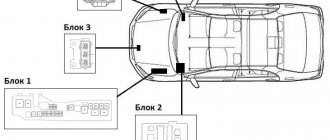
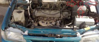
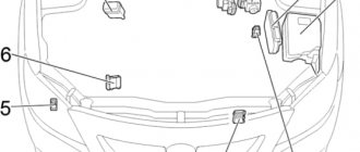
You can find the fuse box under the hood: The control unit is also under the hood. You can find the control unit by the tubes coming from the brakes and wires. The control unit may receive mechanical damage, so you must first inspect it visually. You will first need to remove the electrical wire from it. Check if water has entered the unit: After washing, a similar problem may also occur, as moisture gets into the wiring.
ABS electronic module The anti-lock control unit is located next to the instrument panel.
What is ABS system
ABS stands for "Antilock-breaking System". In Russian it will sound like this: “Anti-lock braking system.” This standard was developed in 1936 by the German company Bosh. In the last century, it was installed on luxury cars at will.
Since 2004, the standard for locking and unlocking wheels during braking has been adopted by all car companies in Europe and around the world. Since then, every car, be it Toyota or Volkswagen, has ABS installed.
Attention! Anti - Blocking System helps increase the safety of the driver and passengers when braking when skidding on a slippery section of the road.
But car owners sometimes do not have a complete understanding of it. What kind of ABS system this is and how it works will be discussed in the next block.
What does the Toyota anti-lock wheel system consist of?
When answering the question “What is ABS?”, it is important to talk about the structural component of the system. The function of locking and unlocking wheels on Toyota cars is controlled by several mechanisms at once:
- The brain of the system is the control unit. It receives signals from sensors, processes them and sends commands to the magnetic valves of the valve body. These actions are performed in milliseconds. In 1 second, the wheel manages to brake and start moving 15 times.
- Hydraulic block. It is located between the brake calipers and the master cylinder. The hydraulic unit regulates the oil pressure in the hydraulic system, regardless of whether the driver presses the brake pedal or not.
- Touch speed sensors. They count the number of wheel spins made. Send data to the control unit.
- Braking mechanisms. They wait for commands from the brain of the system and act as they arrive.
Attention! A light with the letters ABS on the dashboard lights up when one of the mechanisms has failed.
The ABS system can be four-channel, three-channel, two-channel and single-channel. The number of channels depends on the valves that control the pressure in the hydraulic system. There is one channel for each wheel.
Modern Toyotas use four-channel ABS. Other types of anti-lock braking function are obsolete.
Self-diagnosis in the garage
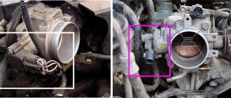
The connector for diagnosing the engine is located near the battery or on the left, along the direction of the car. Often this is a plastic box with the inscription “diagnostics” in English.
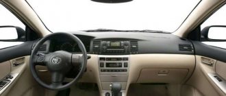
The Toyota Corolla diagnostic instrument panel is located in the driver's cab. The indicator itself on the display can be in the form of an engine, a spiral or a “check” icon. It depends on the year of manufacture and brand of engine, the icon itself is not so important, what matters is the fault codes.
If the automatic transmission is faulty, this will be known using “Power”, “AT Check”, “OD”. Faults in other units will be displayed through their corresponding light diodes.
Socket No. 2 for diagnosing engine malfunctions is located in the cabin, at the bottom of the panel, and this facilitates trouble-free determination of malfunctions while the Toyota Corolla is in motion.
Working principle of ABS
ABS works according to the following principle:
- A sensor device on the wheel hub informs the control unit about braking.
- The release valve opens and the pressure decreases. The brake pads do not slow down the wheel and it continues to rotate.
- This process is repeated several times per second. And the driver feels vibration in the brake pedal.
The system can also maintain pressure due to the operation of inlet and outlet solenoid valves and increase it.
But sometimes the function fails temporarily or permanently. The driver sees this on the dashboard monitor in the form of a flashing anti-lock braking system abbreviation.
Attention! This button may flash for a while when starting the Toyota, as the on-board computer reads information from all sensors. A few seconds after the start it goes out. If not, then you need to check Toyota for errors.
Diagnostic connectors Corolla 120, 150, 180
Error codes on the diagnostic connector DLC 2 of Corolla 120, 150, 180 are supplied in OBD II format. In OBD format, codes are encrypted with 5 characters: the first literal character and the next four numeric characters. The literal character of this code indicates the node where the problem occurred:
The following numbers indicate the exact location of the breakdown, as well as its classification.
Diagnosis of OBD II error codes is possible only with special scanners or by connecting connectors to a computer with special software. After receiving the Corolla codes, fault diagnosis is carried out using a table describing the error codes and their corresponding defects.
ABS errors on Toyota
To identify a malfunction when these three letters appear, you need to know Toyota error codes. To do this, you need to diagnose the car.
Toyota error codes include the following meanings:
- 11 – break in the solenoid valve relay;
- 12 – short circuit;
- 21 to 24 – short circuit in the solenoid of one of the car wheels;
- 31 – 34 – error in the signal from the speed sensor of one of the wheels;
- 41 – battery voltage is too low or too high;
- 51 – the valve body pump motor does not work;
- 52 – valve body pump motor is blocked.
It should be remembered that the codes on Toyotas of different models may differ from each other.
Modern scanners
Reading Corolla fault codes with scanners not only simplifies self-monitoring, but also makes it more informative. Today, manufacturers of diagnostic car scanners supply the market with a wide range of them, differing both in functionality and price. On the one hand, such a market is capable of satisfying the needs of various segments of consumers, but on the other hand, it creates certain difficulties, since it requires some special knowledge when purchasing. Here we will only indicate the main types of diagnostic equipment, as well as its purpose. And this will not be a bad guideline for choosing the right scanner. Based on functionality, scanners are distinguished between dealer, brand and multi-brand.
Dealer scanners are produced by automakers or their contractors, usually for a specific car brand. They have a wide range of functionality and are intended for professional use, and the price can reach several thousand dollars.
The group of brand scanners is also intended for professional use. They have functionality similar to that of the dealer, but more modest. The price of branded scanners ranges from several hundred to a thousand dollars.
Multi-brand scanners are most widespread among motorists. They are easy to use and provide sufficient information for most situations. Scanners of this group are unified for several car brands. Therefore, when purchasing, you need to check their ability to read Corolla error codes.
How to identify a malfunction and fix it
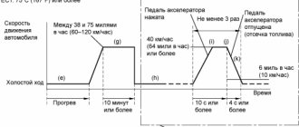
To determine the malfunction, the driver needs to diagnose the vehicle. The car owner can do the procedure independently. The process of searching for Toyota diagnostic codes is carried out as follows for connector DLC1:
- Open the hood and find the connector. It usually says "Diagnostic".
- Turn the ignition key to the on position.
- Insert a jumper between pins TC and E1.
- Remove the closing device from contacts WA and WB.
- After 4 seconds, count the number of flashes of the ABS signal.
- After this, remove the jumper from the codes described in point No. 3 and insert it back between contacts WA and WB.
The car owner will be able to determine Toyota diagnostic codes in the DLC3 connector as follows:
- Repeat steps in point No. 1.
- Before turning on the ignition, insert a jumper between contacts TC and TG.
- Count how many times the ABS abbreviation flashes on the car’s dashboard monitor.
- Set the jumper to the reverse position.
After counting the number of times the light blinked, you must refer to the instructions for an explanation of a particular error.
Trouble-shooting
First of all, you need to check the serviceability of the fuses. Inspect all connections and contacts for wear and poor contact. Make sure that there are no mechanical damage on the sensors: dents from impacts or chips.
If the problem is in the sensor, then you need to do the following:
- Measure resistance and voltage with a tester or oscilloscope.
- If the resistance is less than 800 Ohms, then a short circuit has occurred. At more than 1200 Ohm - break.
- The sensor can be replaced at the service center.
It happens that the problem with ABS lies in the incorrect selection of tires. Therefore they must be the same size.
If the diagnostic codes correspond to numbers 51, 52, 11, 12 and others described in the section above, then you need to contact Toyota technical service.
Table. ABS and EBD system fault codes.
| Fault code | Malfunction | Fault Conditions | Checked elements | |
| 11 | C0278 | Solenoid valve relay circuit open | The solenoid valve relay is in the “ON” position and switches to the “OFF” position for 0.2 seconds or more | |
| 12 | S0279 | Short circuit in the power supply circuit of the solenoid valve relay | Immediately after voltage appears at pin “IG1”. Solenoid valve relay is in the “OFF” position and switches to the “ON” position for 0.2 seconds or more | – ABS solenoid valve relay – Relay wiring harness |
| 13 | S0273 | Open circuit in the electric pump relay circuit | The voltage at pin “IG1” is no more than 10 V when the ignition is turned on (system check) or while the ABS system is operating. The electric pump relay is in the “ON” position and switches to the “OFF” position for 0.2 s or more | – Electric pump relay – Electric pump relay wiring harness |
| 14 | S0274 | Short circuit in the electric pump relay circuit | Electric pump relay is in the “OFF” position and switches to the “ON” position for 3 seconds or more | |
| 21 | S0226 | Open or short circuit in the front right wheel solenoid valve circuit | ||
| 22 | S0236 | Open or short circuit in the front left wheel solenoid valve circuit | 1. The voltage at the “IG1” terminal of the ABS electronic control unit is 10 - 14 V. An open or short circuit in the sensor circuit for 0.05 s or more. | |
| 23 | S0246 | Open or short circuit in the rear right wheel solenoid valve circuit | 2. The voltage at the “IG1” terminal of the ABS electronic control unit is 10 - 14 V when the solenoid valve relay is in the “OFF” position for 0.05 s or more | – Pressure modulator. – Solenoid valve circuit |
| 24 | S0256 | Open or short circuit in the rear right wheel solenoid valve circuit | ||
| 25 | S1225 | Open or short circuit in the purpose of the solenoid valve No. 1 of the master cylinder cut-off | ||
| 26 | S1226 | Open or short circuit in the circuit of the solenoid valve No. 2 of the master cylinder cut-off | ||
| 27 | S1227 | Open or short circuit in the TRC solenoid valve circuit | ||
| 31 | S0200 | Front right wheel speed sensor malfunction | 1. The car is moving at a speed of at least 10 km/h. There are no pulses from the sensor for more than 15 seconds. 2. After turning on the ignition, the signal from the sensor disappears at least 7 times. 3. Open circuit of the sensor lasting more than 0.5 seconds | – Speed sensor – Wiring and connector of the speed sensor – Frequency sensor rotor rotation |
| 32 | S0205 | Front left wheel speed sensor malfunction | ||
| 33 | S0210 | Malfunction of the rear right wheel speed sensor | ||
| 34 | S0215 | Malfunction of the rear left wheel speed sensor | ||
| 35 | S1235 | Foreign material between the rotor and the front right wheel speed sensor | The car is moving at a speed of more than 20 km/h. Signal distortion for more than 5 seconds | – Speed sensor – Speed sensor rotor |
| 36 | S1236 | Foreign material between the rotor and the front left wheel speed sensor | ||
| 38 | S1238 | Foreign material between the rotor and the rear right wheel speed sensor | ||
| 39 | S1239 | Foreign material between the rotor and the rear left wheel speed sensor | ||
| 41 | S1241 | Battery voltage is too high or too low | 1. The car is moving at a speed of at least 3 km/h. The voltage at the “IG1” pin is no more than 9.5 V for 10 s or more. 2. The voltage at the “IG1” terminal is no more than 9.5 V, the solenoid valve relay and the electric pump relay are in the “ON” position. Solenoid valves in steady position. 3. The voltage at the “IG” pin is more than 17 V for 1.2 s or more | – Battery – Voltage regulator |
| 43 | S1243 | Malfunction in the deceleration sensor circuit | (1) The car is stopped -> moving at a speed of more than 30 km/h -> the car is stopped (2) No change in sensor signal (3) More than 16 times (1) The car is moving at a speed of 5 km/h. (2) Terminal voltage. “GS1” of the control unit connector is 1.0 – 2.3 V, at the “GS2” pin – 3.0 – 4.3 V. (3) At least 30 s | – Deceleration sensor – Sensor wiring harness or connector |
| 44 | S1244 | Open or short circuit in the deceleration sensor circuit | (1) Ignition on (2) Open or short circuit in deceleration sensor circuit (3) More than 1 s | |
| 46 | S1243 | Open or short circuit in the pressure sensor circuit in the master cylinder | (1) Supply voltage of the pressure sensor in the main brake cylinder 4.6 - 5.6 V, (2) Signal from sensor 0.14 - 4.85 V. (3) At least 1.2 s (1) The car is moving at a speed of 10 km/h. (2) Significant interference in the sensor signal. (3) 7 times or more in 5 s. (1) The signal voltage from the pressure sensor in the master cylinder is not less than 0.86 V. (2) The sensor signal is not perceived by the control unit. (3) About 60 sec. (1) Brake lights off (2) The voltage at the “RMC” pin is less than 0.3 V or more than 0.86 V (3) More than 5 s | – Master cylinder pressure sensor – Sensor harness or connector |
| 49 | S1249 | Open or short circuit in the brake light switch circuit | The voltage at pin “IG1” is 10 - 14 V. The ABS system does not work. Brake light switch in “ON” position for 1 second or more | – Brake light switch – Wiring harness or switch connector |
| 51 | S1251 | Short circuit or open circuit in the electric pump power supply | The ABS electric pump does not operate during the system check when the ignition is turned on. | – Electric pump, relay and battery – Wiring, connector and ground bolts or electric pump diagram |
| – | ABS control unit malfunction | – | – ABS control unit |