What are the symptoms of P0335?
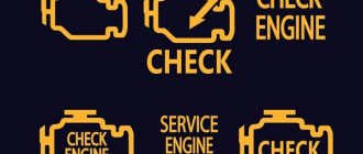
Symptoms of the P0335 code may vary depending on the make and model of your vehicle. Typically, when this error appears, the Check Engine light on the dashboard lights up, but it should be noted that in some cars this light may not light up immediately, but only after the error has been detected multiple times. The main symptoms of a P0335 code include loss of engine power, engine stalling, trouble starting the engine, and decreased fuel efficiency.
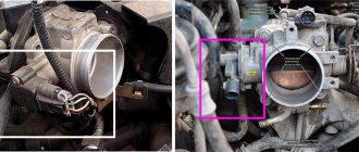
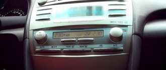
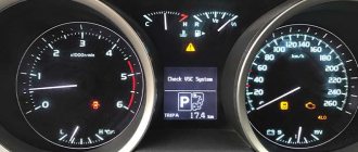
Proper diagnostic work on Camry 50
The sequence for reading the error code is approximately the same for all Toyota cars:
- with the ignition off, connect the scanner to the diagnostic connector,
- establish a connection between the scanner and the phone via Bluetooth, if the diagnostic program is installed as an application on the smartphone; connect the scanner to a laptop computer on which the diagnostic program is installed,
- in the program menu to read the error code, select the Toyota Camry of the required year and body,
- turn on the ignition or start the engine and start scanning,
- the program will display error codes that have been stored in the vehicle control units since the last time the fault codes were deleted,
- delete all errors, drive the car for 2-3 kilometers and read again, now the equipment will show only existing problems, and not all, including those that have been resolved,
- write down the error codes, if the program decrypts, then write down or save the problems shown,
- After completing diagnostic operations, turn off the scanner and ignition.
After the manipulations have been performed, analyze the information received and troubleshoot.
How does a mechanic diagnose a P0335 code?
First, the mechanic reads all the stored data and error codes using an OBD-II scanner. He will then clear the error codes from the PCM and test drive the vehicle to see if P0335 appears again. If the error code appears again, the mechanic will visually inspect the crankshaft position sensor as well as the associated wires.
The mechanic will then check the crankshaft position sensor readings as well as the RPM signal using a scanner. If the readings are within the specified range, the mechanic will check the electrical wires. If no problem is found, the mechanic will check the PCM according to the manufacturer's procedure.
Checking the System Status
Problematic components in this case may be the speed sensor (on front-wheel drive vehicles it is installed on the hub bearing, on rear-wheel drive vehicles - on the gearbox or differential), the instrument panel (panel, its electronic part), the on-board control system (ECM in the English abbreviation). Before checking, it is advisable to make sure that the speedometer in the car is working correctly. It’s easy to verify this by taking a short trip.
If error code P0500 occurs, you must do the following:
- Using special diagnostic equipment, it is checked whether the speed sensor is working properly. If the appropriate equipment is not available, then you can install a known working sensor of a similar model on the machine.
- Using a multimeter, check whether the circuit between the sensor input signal and its ground or power wire is closed (often, it is due to insulation failure that a short circuit occurs in the circuit, and, accordingly, incorrect operation of the sensor and the entire system).
- Using a diagnostic tool, find out whether the forming voltage from the sensor arrives several times per second along the signal cable. Moreover, the connection may be interrupted for the first few seconds, but then restored again.
- The connection between the sensor and its ground is checked.
- If the sensor is four-wire, then the integrity of the fourth wire is also checked using a multimeter.
Please note that when starting and stopping the car in place, the connection with the sensor is interrupted, but is restored immediately while moving. Therefore, the verification process is performed according to a certain algorithm
Additional comments for troubleshooting P0335
The crankshaft position sensor is used to monitor the crankshaft speed. The vehicle's PCM uses data from the crankshaft position sensor and camshaft position sensor to regulate ignition timing and fuel distribution.
Properly diagnosing the P0335 code requires an advanced scan tool that can not only read stored trouble codes, but also allow you to view readings from various sensors in real time.
TEST SEQUENCE
NOTE:
- If the fault is not detected during the diagnostics, search for a fault in the mechanical part of the engine.
- Check the engine speed. Engine speed can be checked using a handheld scan tool. To check, follow these steps: Connect the handheld diagnostic tool to the DLC3.
- Start the engine.
- Turn on the portable diagnostic tool.
- Select the following menu items: Powertrain / Engine and ECT / Data List / Engine Speed.
- According to the readings, the engine speed may be zero during normal engine operation. This is caused by a lack of NE signals from the crankshaft position (CKP) sensor. In addition, the engine speed reading may be lower than the actual speed if the CKP sensor output voltage is insufficient.
| 1. TAKE READINGS ON THE PORTABLE DIAGNOSTIC TOOL (ENGINE SPEED) |
Connect the handheld diagnostic tool to the DLC3.
Turn on the ignition (IG).
Turn on the portable diagnostic tool.
Select the following menu items: Powertrain / Engine and ECT / Data List / Engine Speed.
Start the engine.
Read the values displayed on the scan tool while the engine is running.
OK: Valid values are displayed. NOTE:
- To check changes in engine crankshaft speed, display a graph on the device display.
- If the engine does not start, check the engine speed when cranking with the starter.
- If the engine speed displays zero (0), there may be an open or short circuit in the crankshaft position sensor circuit.
| OK |
| NG |
| 2.CHECK CRANKSHAFT POSITION SENSOR (RESISTANCE) |
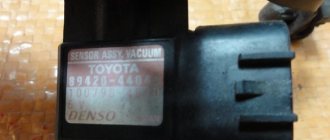
Disconnect the crankshaft position sensor (CPS) connector B22.
Measure the resistance between pins 1 and 2.
Nominal resistance:
| Contacts for connecting a diagnostic tool | Mode | Specified conditions |
| 1 — 2 | Cold | 985-1600 Ohm |
| 1 — 2 | Hot | 1265-1890 Ohm |
NOTE: The terms “cold state” and “hot state” refer to the temperature of the sensor.
“Cold condition” means approximately -10 to +50°C (14 to 122°F). “Hot” means approximately +50 to +100°C (122 to 212°F). Connect the SKR sensor connector.
| NG |
| OK |
| 3.CHECK HARNESS AND CONNECTOR (CRANKSHAFT POSITION SENSOR - ECM) |
Disconnect connector B22 of the SKR sensor.
Disconnect ECM connector B32.
Measure the resistance of the connectors on the wiring harness side.
Nominal resistance (check for open):
| Contacts for connecting a diagnostic tool | Specified conditions |
| NE+ (B22-1) - NE+ (B32-122) | Less than 1 ohm |
| NE- (B22-2) - NE- (B32-121) |
Nominal resistance (check for short circuit):
| Contacts for connecting a diagnostic tool | Specified conditions |
| NE+ (B22-1) or NE+ (B32-122) - mass | 10 kOhm or more |
| NE- (B22-2) or NE- (B32-121) - weight |
Connect the ECM connector.
Connect the SKR sensor connector.
| NG |
| OK |
| 4.CHECK SENSOR INSTALLATION (CRANKSHAFT POSITION SENSOR) |
Check the installation of the SKR sensor.
OK: The sensor is installed correctly.
| NG |
| OK |
| 5.CHECK THE CRANKSHAFT POSITION SENSOR TOOTH (SENSOR DISC TEETH) |
- Check the teeth of the sensor disk.
OK: The sensor toothed disk is not cracked or deformed.
| NG |
| OK |
| 6.REPLACE CRANKSHAFT POSITION SENSOR |
| FURTHER |
| 7.CHECK IF DTC CODE IS OUTPUT AGAIN |
Connect the portable diagnostic tool to the DLC3 connector.
Turn the ignition switch to ON (IG) and turn on the handheld scan tool.
Clear DTCs (See page Click here).
Start the engine.
Select the following menu items: Powertrain / Engine and ECT / DTC.
Read DTCs.
Result:
| Indication (Displayed DTCs) | Next step |
| Not displayed | A |
| P0335 or P0339 | B |
HINT: If the engine does not start, replace the ECM.
| B |
| A |
| END |
On which cars is this problem most common?
The problem with code P0012 can occur on different machines, but there are always statistics on which brands this error occurs more often. Here is a list of some of them:
- Audi (Audi a4)
- BMW (BMW X3, BMW X5)
- Chevrolet (Chevrolet Aveo, Cruz)
- Chrysler
- Citroen (Citroen C3, C5)
- Fiat (Fiat Doblo)
- Ford (Ford Kuga, Mondeo)
- Geely (Gili Emgrand)
- Hyundai (Hyundai Elantra)
- Kia (Kia Sid, Sorento, Cerato)
- Land Rover (Land Rover Range Rover)
- Lexus
- Lifan
- Mazda (Mazda 3, Mazda 6, Mazda cx7, Demio, MPS)
- Mercedes
- Nissan
- Opel
- Peugeot (Peugeot 307, 308, 407, 3008)
- Renault (Renault Logan)
- Skoda
- Suzuki (Suzuki Grand Vitara)
- Toyota (Toyota Avensis, Camry, Corolla, Prado, Prius, Rav4, Scion, Yaris)
- Volkswagen (Volkswagen Passat)
- Volvo
- Vortex (Vortex Tingo, Estina)
- Lada Vesta
With fault code P0012, you can sometimes encounter other errors. The most common are: P0010, P0011, P0015, P0016, P0018, P0020, P0021, P0022, P0102, P0170, P0171, P0174, P0300, P0301, P0302, P0303, P0304, P0305, P0306, P031 6, P0340, P0345, P0352 , P0607, P1297, P1415, C1201, C1231.
Ride in test mode
This test drive mode is used in the “PERFORM TEST RIDE” procedure in the following diagnostic procedure.
The fuel supply is stopped when the following conditions are met:
When performing this test drive, you must strictly adhere to the posted speed limits and traffic regulations.
Description
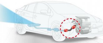
The A/F sensor outputs a voltage* that corresponds to the actual air-fuel ratio. This voltage is used as a feedback signal to the ECM, through which the latter regulates the air-fuel ratio. The ECM detects deviations from the stoichiometric air-fuel ratio and adjusts the timing of fuel injection. If the A/F sensor fails, the ECM cannot accurately control the air/fuel mixture.
The A/F sensor is a planar type sensor and is equipped with a heater that heats the solid electrolyte (zirconium cell). The heater is controlled by the ECM. When the intake air volume is low (low exhaust gas temperature), current begins to flow through the heater, warming the sensor and providing an accurate determination of the air-fuel ratio. In addition, this sensor and heater is narrower than conventional sensors. The heat generated by the heater is transferred to the solid electrolyte through the aluminum, thus accelerating the activation of the sensor. To achieve a high degree of purification of exhaust gases from carbon monoxide (CO), hydrocarbons (CH) and nitrogen oxide (NOx), a three-component catalytic converter is used. To use TWC most effectively, the fuel mixture must be precisely controlled so that its composition is consistently stoichiometric. *: The value changes in the ECM. Since the A/F sensor is a current output element, the current is converted to voltage by the ECM. If measurements are taken, a constant voltage will be observed at the A/F sensor and ECM connectors.