In modern cars it is no longer possible to determine a breakdown “by eye”; more accurate computer diagnostics are needed. A timely and correctly made “diagnosis” will allow you to quickly begin repairs with a high chance of success.
In the Toyota Camry, manufacturers have prudently “hardwired” error codes into the on-board electronics so that the process of identifying faults takes as little time as possible. A warning about the presence of errors is the Check VSC System notification, which lights up on the on-board computer screen.
What do the codes mean?
The table below shows the most common errors in Toyota Camry.
| Error codes | Meaning | Reasons for appearance |
| P035(1,2,3,4,5,6) | Problems with the ignition coil (P0355 and P0356 can only occur on V6 engines). | This may be a signal that the wiring is faulty, the ignition coil is not working, or the control unit is not functioning. |
| P0172 | Over-rich fuel mixture. | Incorrect operation of sensors, insufficient compression, incorrect gas distribution, deformation, loss of seal integrity. |
| P0137, P0157 | Low voltage to oxygen sensor. | Open circuit, broken lambda probe, exhaust gas leak. |
| P2237(8) | Weak current or interruption of current to the lambda sensor. | Open or short circuit in the sensor circuit. |
Lean burn engine lambda probe.
WhiteGoose : I fiddled with the poor sensor for a long time, and realized that this is some kind of intermediate stage of development between a regular oxygen sensor and a broadband sensor. To take readings, a certain potential difference is applied to it with a floating reference voltage of 3-3.3 volts for some reason. If the mixture is lean, then the ECU can determine the degree of leanness based on the current through the sensor. If it is rich, the sensor is locked and no current flows through it, regardless of the composition of the mixture. And the ECU only states that the mixture is rich. Is it possible to use a regular heated oxygen generator so that the check does not light up? I don’t know, I haven’t looked into it that deeply. It is only clear that there will be no sense from this; there will still be no correction of the composition of the mixture.
Decoding error codes on Toyota cars
Technical defects appear sooner or later in cars of all manufacturers, including Japanese ones. The driver can decipher Toyota error codes independently, and it is possible to determine system malfunctions without the use of scanners. If a car enthusiast has never encountered such a problem before, then this article will help you understand all the nuances and perform the work at a professional level.
Toyota self-diagnosis.
Modern Toyota cars, and other brands as well, are quite progressive mechanisms that have the ability to automatically control their own systems and sensors. If errors are found in operation, they signal the driver about the presence of a malfunction on the dashboard with a warning indicator lamp. Models with a digital display may even display an error code or the name of the faulty unit.
Toyota self-diagnosis begins with the fact that you first need to locate the corresponding diagnostic connector. This connector may be located under the hood, in the engine compartment and/or under the driver's instrument panel. In cars of this brand, three different types of self-diagnosis connectors were used:
Connector type DLC1 is located in the engine compartment, and connectors DLC2, DLC3 are located under the driver’s dashboard.
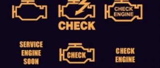
Errors during self-diagnosis are read by the blinking of the indicator lamp of the corresponding readable unit. For example, engine malfunctions must be read by the flashing of the “Check engine” lamp (engine image).
Toyota car diagnostics
Diagnostics are available on cars of the entire Toyota model range and are divided into two types:
Before starting electronic diagnostics, the driver must ensure that all systems and main mechanisms of the Toyota vehicle are in working order. To do this, you should check the fuses, electrical wiring, and also examine the connections and components of the vehicle for damage.
If any serious problem is detected, it must be eliminated, and only then carry out computer diagnostics, which can happen:
Step-by-step self-diagnosis
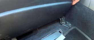
For self-diagnosis, the driver needs to work with the DLC 1 and DLC 2 connectors. This abbreviation stands for Data Link Connector, which in English means a connector for connecting data. DLC 1 looks like a plastic box with a lid on top. It is located under the hood, most often on the left. It is easy to find by the inscription Diagnostic.
Diagnostic signature on the connector
In older models, the diagnostic connector is shaped like a yellow circle and is located near the battery. There are no DLC2 parts in cars like the Corolla AE 100.
Fault codes for older car models: Toyota Corona 1992, Karina 1992-97, Toyota Mark are read only by flashing indicators.
In new models, DLC 2 is located directly in the cabin, under the dashboard and “at the feet” near the steering wheel. Most often it is round and is used during inspections carried out using special equipment.
Round DLC2 connector
When performing self-diagnosis by shorting individual contacts of the connector, only by connecting them in the required sequence can you obtain the correct code for decoding.
The following steps will help you find out if there are faults in the engine and/or gearbox system:
DLC 1 connector diagram
Everything is fine with the car and no damage to the internal combustion engine or transmission was detected if:
Any other combinations of light bulbs indicate a malfunction in the engine systems, gearbox or other mechanisms in the car.
If the circuit on the back of the cover has been erased, you cannot find the contact or you are not sure that you have closed the right one, you must:
It will be more convenient if someone helps you monitor the light bulb while you change the position of the wire.
Recognize fault codes using two flashing light systems.
The first setting option will allow you to find out errors indicated by a two-digit code (type 09):
Using the 10th setting type, unambiguous codes are determined. Here the light “blinks” the exact error number.
This code should be “read” according to the following rules:
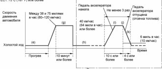
The video shows diagnostics using type 9 code, author Dmitry Kuzmin:
Failures in the ABS system are determined using the same scheme, but the TC and E1 terminals are closed. The SRS and 4WS fault codes are read by the corresponding sensor with the same contacts closed as in the ABS.
Photo gallery “Self-diagnosis of Toyota cars”
Diagnostic connector DLC 1
Contacts TE1 and E1 on the connector
Closing contacts
Location of the connector under the hood
Toyota self-diagnosis.
Modern Toyota cars, and other brands as well, are quite progressive mechanisms that have the ability to automatically control their own systems and sensors. If errors are found in operation, they signal the driver about the presence of a malfunction on the dashboard with a warning indicator lamp. Models with a digital display may even display an error code or the name of the faulty unit.
Toyota self-diagnosis begins with the fact that you first need to locate the corresponding diagnostic connector. This connector may be located under the hood, in the engine compartment and/or under the driver's instrument panel. In cars of this brand, three different types of self-diagnosis connectors were used:
Connector type DLC1 is located in the engine compartment, and connectors DLC2, DLC3 are located under the driver’s dashboard.
Errors during self-diagnosis are read by the blinking of the indicator lamp of the corresponding readable unit. For example, engine malfunctions must be read by the flashing of the “Check engine” lamp (engine image).
Troubleshooting
Type 9 error codes common to all Toyota vehicles are represented by two-digit codes.
| Code | Decoding |
| 11 | No power to EFI unit |
| 12 | No signal from the engine speed sensor |
| 13 | No signal from the engine speed sensor at speeds above 1000 rpm |
| 14 | There is no signal from the minus ignition coil or from the minus coil number one (if there are two of them) |
| 15 | There is no signal from the minus of ignition coil number two |
| 16 | There is no connection between the automatic transmission control unit and the engine control unit |
| 17 | Incorrect signal from camshaft position sensor number 1 |
| 18 | Incorrect signal from camshaft position sensor number 2 |
| 21 | Incorrect signal from the oxygen sensor, if the engine is V-shaped, then the heater of the left main oxygen sensor is faulty |
| 22 | Incorrect signal from engine temperature sensor (THW) |
| 23 | Incorrect signal from the intake air temperature (THA) sensor |
| 24 | Incorrect signal from the intake air temperature (THA) sensor |
| 25 | Mixture too lean |
| 26 | Mixture too rich |
| 27 | Incorrect signal from the additional oxygen sensor (left for V-engines) |
| 28 | Incorrect signal from the oxygen sensor (on V-engines, the heater of the right main oxygen sensor) |
| 29 | The additional oxygen sensor is faulty (right for V-engines) |
| 31 | Incorrect signal from the air flow sensor or, if there is none, from the pressure sensor in the intake manifold (vacuum sensor) |
| 32 | Incorrect signal from air flow sensor |
| 34 | Boost faulty |
| 35 | Incorrect signal from the atmospheric pressure sensor in the intake manifold (vacuum sensor) |
| 38 | Automatic transmission fluid temperature sensor |
| 41 | Incorrect signal from throttle position sensor (TPS) |
| 42 | Incorrect signal from the vehicle speed sensor (speedometer) |
| 43 | No starter signal (STA) to engine control unit |
| 46 | Solenoid valve number 4 or its circuits are faulty |
| 47 | The auxiliary throttle position sensor (TPS) or its circuit is faulty |
| 48 | The auxiliary air supply control system is faulty |
| 51 | No idle signal from TPS |
| 52 | Incorrect signal from the knock sensor (if there are two of them, then from the left or from the front) |
| 53 | Problems in knock sensor control circuits (ignition timing) |
| 55 | Incorrect signal from the knock sensor (if there are two of them, then from the right or from the rear) |
| 61 | The main speed sensor or its circuit is faulty |
| 62 | Solenoid valve number 1 or its circuits are faulty |
| 63 | Solenoid valve number 2 or its circuits are faulty |
| 64 | Solenoid valve number 3 or its circuits are faulty |
| 65 | Solenoid valve number 4 or its circuits are faulty |
| 67 | The O/D switch or its circuit is faulty |
| 71 | EGR control system faulty |
| 72 | Fuel cut solenoid |
| 77 | The pressure control solenoid or its circuit is faulty (in the machine) |
| 78 | There is no signal to the fuel pump or its circuits are faulty |
| 81 | The circuit between TCM and ECT1 is faulty |
| 82 | The circuit between TCM and ESA1 is faulty |
| 84 | The circuit between TCM and ESA2 is faulty |
| 85 | The circuit between TCM and ESA3 is faulty |
| 86 | Engine speed sensor is faulty |
| 88 | The circuit from the engine control unit to the automatic transmission control unit is faulty |
| 89 | Communication between the engine control unit and the TRC system control unit is broken |
| 99 | No fault codes |
The general list of unambiguous codes (type 10) for a Toyota car consists of the following items.
| Code | Decoding |
| 1 | No breakdowns |
| 2 | The air flow sensor gives an incorrect signal |
| 3 | Incorrect signal from the communicator |
| 4 | The coolant temperature is outside the normal range, the sensor has failed |
| 5 | Incorrect communication with the oxygen sensor |
| 6 | The fault lies in the number of engine revolutions |
| 7 | Throttle valve in incorrect position |
| 8 | The sensor shows incorrect intake air temperature |
| 9 | Car speed problem |
| 10 | There is no starter signal |
| 11 | The air conditioner is broken or the toggle switch responsible for the neutral position in the car is faulty |
Gasoline internal combustion engines
If the car has an on-board computer or robot, the code will appear on the mileage screen. It will consist of a Latin letter at the beginning, for example P, B, C, and 4 numbers. This is typical for cars such as Toyota Rav 4 Avensis, Corolla, Mark II or Land Cruiser 200, Toyota Prado 120 and others that run on gasoline.
Table for deciphering diagnostic fault codes for gasoline internal combustion engines.
| Codes | Decoding | Analogue on BC |
| 12 and 13 | Problems with the crankshaft position sensor | P0335, P0335, P1335 |
| 14 and 15 | Problems with the ignition system or coils | P1300 and P1315, P1305 and P1310 |
| 18 | VVT-i phase system | P1346 |
| 19 | Accelerator pedal position | P1120 and P1121 |
| 21 | Oxygen sensor | P0135 |
| 22 | Coolant temperature | P0115 |
| 24 | Damage to the intake air temperature sensor | P0110 |
| 25 | Oxygen sensor - lean mixture | P0171 |
| 31 | Absolute pressure sensor | P0105 and P0106 |
| 36 | CPS sensor | P1105 |
| 39 | VVT-i system | P1656 |
| 41 | Throttle position | P0120, P0121 |
| 42 | Vehicle speed sensor problems | P0500 |
| 49 | Fuel pressure D-4 | P0190, P0191 |
| 52 and 55 | Knock sensor failure | P0325 |
| 58 | SCV drive | P1415, P1416, P1653 |
| 59 | Incorrect VVT-i signal | P1349 |
| 71 | EGR system | P0401, P0403 |
| 89 | ETCS drive | P1125, P1126, P1127, P1128, P1129, P1633 |
| 92 | Cold start injector problems | P1210 |
| 97 | Injector faulty | P1215 |
Diesel engines
Many Toyota cars were produced with a diesel engine. The most popular models are the Vitz, Caldina, Avensis (T25), Camry, Camry Grazia, Corolla E150, Auris 2008 sedans, Land Cruiser Prado 120 and Land Cruiser Prado 200 SUVs or the RAV4 crossover.
When writing down codes for diesel cars, you can see the following symbols.
| Code | Decoding |
| 13 | Rotation speed is outside the permissible limits |
| 19 | Incorrect accelerator pedal position |
| 22 | Malfunction in coolant temperature indicators |
| 24 | Incorrect intake air temperature data |
| 35 | Boost pressure is out of range |
| 39 | Fuel temperature sensors do not work well |
| 42 | The fault lies in the vehicle speed sensor |
| 96 | EGR valve position is incorrect |
Failure of other diesel engine parts.
| Code | Decoding |
| 12 | Crankshaft position problem |
| 14 | Damage to the valve that regulates the injection advance angle |
| 15 | The throttle servo is faulty |
| 17 | Incorrect signal coming from the control unit |
| 18 | Damage to the solenoid bypass valve |
| 32 | Failure of correction resistors |
Automatic transmission
Cars of the same brand differ not only in the engine, but also in the gearbox. For the same Toyota Corolla 150, Celsior or Vista, automatic transmission failures will differ from mechanical failures.
If there is a malfunction in the transmission, you will see one of the codes.
| Code | Decoding | Analogue for automatic transmission |
| 37 | Transmission input shaft speed sensor malfunction | P1705 |
| 42, 44, 36 | The problem is in the speed sensor (maybe shaft speed) | P0500 |
| 46 | Accumulator pressure, solenoid faulty | P1765 |
| 62, 63 | Problems with one of the solenoids | P0753 P0758 |
| 64, 68 | Torque converter lock-up clutch, solenoid faulty | P0773 |
Such errors are typical for different models, including Toyota Ipsum, Toyota Highlander 2001 and Caldina.
Other combinations
Special equipment and devices are also used for diagnostics. Such devices will show five-digit codes. They can also be recognized using the on-board computer, which is installed in new cars and hybrid models.
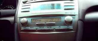
Code on the Toyota screen with on-board computer
Toyota Estima, Toyota Prius, third generation Toyota Harrier and others came out in the hybrid version. These models (in addition to other breakdowns) may experience malfunctions of the high-voltage battery system (HVB). Hybrid installation error codes and their interpretations are given in the table.
The most common non-VVB error codes are:
| Code | Decoding |
| P1604 | Engine starting failed, failure in the intake system |
| B0101 | The security system does not work correctly, there are problems with the airbags |
| In 1801 | The squib circuits on the driver's side are broken. |
| C1201 | Engine operation is incorrect, speed is below the permissible level |
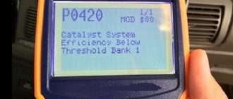
| P0420 | Catalyst system B1 operates below the permissible efficiency threshold |
| P0352З | Problems in the ignition system circuits |
The photo gallery shows errors in the operation of the immobilizer and tires on Toyota cars.
How to do a Toyota self-diagnosis?
In order to start engine self-diagnosis, you need to close the “TE1” and “E1” contacts in the DLC1, DLC2 connectors in the diagnostic connector with a paper clip, and if self-diagnosis is carried out using the DLC3 connector, then close the “TC” and “CG” contacts. The location of the contacts, by the way, is usually located under the protective cover of the connector. After this, turn on the ignition and observe the warning lamp. If there are no faults, the lamp blinks constantly at a frequency of a quarter of a second. If there are problems, the blinking of the lamp displays the fault code in digital form. First of all, the number of tens is displayed by long moments of lamp burning, after (after 1.5 seconds) units are displayed by more frequent blinking of the lamp. For example, three long and two short lamp beeps indicate code “32”. If there is more than one fault in the memory, then the next code is displayed after an interval of about 2.5 seconds. All codes are repeated in a cyclic circle, the pause between rows of codes in a circle is 4.5 seconds.
You can decipher the code using the table of fault codes for your car. This table is very often published in service books for repairing a specific car. In addition, the World Wide Web contains special sites with databases of fault codes for most modern cars and their decoding; application stores of modern smartphones, by the way, can also contain programs of this kind, which is very convenient.
In the same way, you can diagnose other systems:
To do this, you need to close or open the necessary connectors in the diagnostic block. Which connectors need to be closed to diagnose the corresponding mode in brief:
In conclusion, I would like to note that the Toyota self-diagnosis system is the first direction of movement towards a malfunction. And we cannot immediately talk about a specific failure of any sensor, because a simple interruption in the power supply to the circuit or its contamination is possible. So, having decided on the direction, it is necessary to test a specific node for performance.