During the computer check, a special built-in device is used - a diagnostic connector.
At the same time, the quality of operation of the injection engine, gearbox, electronic sensors, security system and other actuators is diagnosed. Errors recorded on the electronic control unit (ECU) are analyzed.
Self-diagnosis procedure
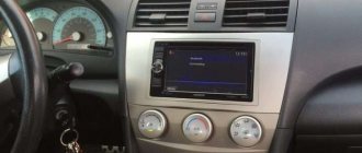
This function is available if the climate control on the Camry 40 is equipped with a unit with an LCD display. On older versions of units, diagnostics can only be carried out using a car scanner by connecting to the standard connector located near the steering column.
Self-diagnosis procedure
We are trying to carry out self-diagnosis of the climate systems in the car, you need to perform the following steps:
- Turn off the engine, turn off the ignition.
- Simultaneously press the Auto button on the climate control panel and the button that activates internal air circulation.
- While holding the buttons, turn on the ignition. At the same time, all indicators located on the remote control display will begin to blink, which indicates the start of the self-diagnosis process.
- After checking the display and diagnostics of the sensors, an error code will be displayed on the display in the place where the temperature is normally displayed.
- If 2 or more errors occur, they are displayed alternately, starting with the smallest code.
The climate control on the Toyota Camry is equipped with a considerable number of electric drives, the functionality of which can be checked by switching to self-diagnosis mode. To do this you need:
- Start the system self-diagnosis process as described above, then press the button that activates air circulation inside the cabin. Important: diagnostics must be performed on a fully warmed-up internal combustion engine.
- During the test, various fan operating modes will turn on alternately, with a delay of 1 second, and the dampers will open/close.
- You can increase the interval for changing modes by pressing the windshield defogger button.
- To exit the test mode for drives, relays and fans, press the AUTO button - in this case, the control unit will switch to the sensor test mode.
The diagnosis is completed by pressing the Off button.
Climate control for Toyota Camry
The climate control control unit on the Toyota Camry supports the memory clearing function. It should be carried out after eliminating errors that arose during the self-diagnosis process. It is performed as follows:
- The control unit is put into diagnostic mode.
- Press the front window heating and rear window heating buttons at the same time.
- The error memory has been cleared.
There are many reasons why the climate control on a Camry 50 or 40 shows errors during self-diagnosis: from missing contact to sensor failure.
Possible malfunctions that occur during climate control operation are as follows:
- sensor malfunction. Fixed by replacing it;
- control unit malfunction. Often, to fix the problem, it is enough to simply disassemble it and solder all the contacts;
- Damaged electrical wiring or sensor connectors. This often occurs as a result of unqualified intervention in the electrical equipment of a car;
- weak compressor drive belt tension or damage. In this case, you need to check the integrity of the belt;
- failure of the electromagnetic clutch sensor installed in the compressor;
- compressor failure or blockage;
- leakage or lack of refrigerant, or its level does not correspond to that established by the car manufacturer;
- lack of contact with the instrument panel or engine ECU.
It is also worth noting that the climate control on Camry 40 or 50 must be diagnosed in a well-lit room or outdoors - otherwise a light sensor error may occur.
The most common indicators
Fuel problems
This error has code value B 1206. Errors, according to the comments of many users, can occur for various reasons. Often this value is shown on the display during mechanical shocks to the car, as well as in the event of excessive fuel consumption associated with engine breakdowns. Despite the prevalence of this problem, if the treasured numbers are discovered, it is necessary to contact specialists who will conduct a full diagnosis and identify faults.
Indicator “low efficiency of catalysts”
If the numbers P0420 appear, these are error codes indicating insufficient efficiency of the catalyst system.
If the problems are not corrected in a timely manner, you will have to spend considerable effort and money on restoring the Toyota Camry automobile unit.
It’s bad if the resource is exhausted, but the problem can be solved: contact a specialized service, where you (or rather, your car) will be helped and assisted in finding problems.
Error 1604
This situation (referred to as P1604) indicates the presence of several (or one) unsuccessful attempts to start the car engine. The solution to the problem depends on the reason why the launch failed. If this is an incorrect start or mechanical action, it is worth trying again; if it is frosty or cold, reheat the unit. If the reason is unclear, only a qualified technician can provide proper assistance in solving this problem. The erroneous parameter P1604 is common, but this does not mean that it can be ignored.
Error value A799
This parameter can be deciphered in different ways, depending on the nature of the malfunction. This may indicate a malfunction of several elements or exceeding the course speed. Errors 799 are less common than other faults, but nevertheless they do occur. The first action that the driver must take is to understand the cause of the problem in order to ensure the stability of all vehicle systems. A competent approach to solving the problem will ensure your peace of mind and constant comfort.
Description of the self-diagnosis process
First you need to check that the battery has a voltage of at least 11 volts, the throttle valve is closed, and all electrical appliances are turned off. For convenience, you also need to prepare a homemade jumper from a metal clip or wire.
- turn off the ignition;
- using a paper clip, close the 4th and 13th contacts on the OBD-II connector;
- turn the key to “ON” mode (do not start the engine);
- after 4 seconds, read the ABS error code;
- remove the jumper clip from the installed contacts.
The error is indicated by two numbers: the first is counted by the number of blinking indicator lights every 0.5 seconds, then a break, the second is also counted by the number of blinks with an interval of 0.5 seconds. After 2.5 seconds, the next code is issued, etc. When all codes have been issued, after a break of 4.5 seconds, the codes are issued again. If there are no errors, the interval between signals is 0.25 seconds.
Two-digit ABS codes are deciphered using special tables.
Modern scanners
There are now many scanners available for reading car error codes that completely decipher error codes. These programs are translated into Russian, are easy to use and allow you to configure vehicle parameters. For example, the time when the headlights go out after turning off the ignition, after how many seconds the lights in the cabin go out when boarding, disembarking, and more.
The car owner should think about purchasing diagnostic equipment. Not bad manufacturers of diagnostic devices: Launch, ELM, Autel, Autocom, Carman.
How to turn off the ABS lamp
Next, you need to eliminate the identified faults. To stop the warning light from flashing, it is not enough to eliminate the fault. To turn it off, do the following:
- Start the engine and drive for half a minute at a speed of 20 km/h.
- Make sure the ABS light is not flashing.
- Reset error code.
If this does not help, the lamp continues to blink, there is a second option:
- Stop the car for 5 - 7 seconds.
- Press the brake pedal several times.
- Continue driving at a speed of 50 km/h.
- Depress the brake pedal for three seconds.
- Repeat three times.
After the ABS light goes out, you need to reset the error code.
Reset errors
After the repair has been made and the breakdown has been fixed, the error codes may not disappear on their own. There is also a certain sequence of actions to reset them. To do this, we again need a diagnostic connector.
To reset codes you need to:
- Turn on the ignition.
- At the DLC1 connector, short-circuit the TC and E1 terminals with a piece of wire or wire.
- In 3 seconds, press the brake as many times as possible, but not less than 8.
- Make sure the light blinks evenly at half-second intervals.
- Turn off the ignition and remove the jumper from the contacts.
- Make sure that the ABS indicator does not light up.
“Artem0023” explains in the video how to carry out self-diagnosis of Toyota cars step by step:
6.2.2. Self-diagnosis (OBD) system and codes
Digital voltmeter
Warning
On models from 1990 to 1994, the OBD1 self-diagnosis system is installed, and since 1995, the OBD2 self-diagnosis system is installed.
To determine fault codes in the OBD1 system, you simply need to disconnect the test connector located under the instrument panel. But to determine fault codes in the OBD2 system, you must use a special device to view fault codes. To diagnose the exhaust gas emission reduction system and control engine operation, it is advisable to use a digital voltmeter, which has a high input resistance and does not affect the operation of the circuit being tested (see Fig. Digital voltmeter ).
To determine fault codes and analyze engine control systems, it is necessary to use special scanners (see fig. Scanner ).
The ECM contains a built-in self-diagnosis system that detects and classifies faults in electrical circuits. When the ECM detects a malfunction, the check engine light comes on, the malfunction is identified, and a fault code is written and stored in memory.
There are four methods for self-diagnosis of engine malfunction. The check engine light comes on if there is a fault in the U-mode.
most user friendly.
Memory reading method.
Designed for the maintenance department to check stored fault codes.
Used to check faulty parts.
Cleaning method.
Designed to delete recorded fault codes.
| A digital voltmeter is used to diagnose the emission control system and control engine operation. | The scanner is used to determine fault codes and analyze engine management systems. |
| EXECUTION ORDER |
| 2. Turn on the ignition without starting the engine and check that the check engine light in the instrument cluster is on. | |
| 3. Watch the check engine light, which will highlight fault codes stored in the computer's memory. If there are no fault codes, the check engine light will not light up. If the check engine light flickers, it means that the fault method test connector is not disconnected. | |
| 4. Observe the check engine light to determine any fault codes. The first digit of the fault code is displayed with long flashes, and the second digit of the fault code is displayed with short flashes. For example, 4 long flashes represents the number 4, and two short flashes represent the number 2, that is, fault code 42. |
Toyota Error Codes
Toyota error codes are encrypted information about existing malfunctions in the operation of the engine and its systems or automatic transmission. Modern models are equipped with electronic control modules with self-diagnosis systems. They are designed to optimize the operation of equipment, reducing fuel consumption and minimizing the toxicity of exhaust gases.
You can read and decipher Toyota errors at the specialized Toyota Dubrovka car service center. Our diagnosticians have been certified by the manufacturer and work according to its regulations; they will carry out the appropriate measures and provide all the necessary information to the car owner in a printout.
Toyota error codes: how are they read?
In order for the Toyota electronic control module to be able to receive the necessary data from the systems it controls, they are all equipped with sensors.
If deviations from the norm established by the manufacturer in the sensor readings are detected, an emergency mode is launched, accompanied by a corresponding indication on the dashboard.
If the normal operating parameters of the sensor are restored (after repair, replacement or independently), the standard operating mode and the engine or automatic transmission return. At the same time, data that malfunctions have been identified are recorded in the database in the form of Toyota codes and remain there.
Toyota malfunctions can manifest themselves in different ways: it happens that the engine stalls, attracting the attention of the driver who seeks auto repair help, and it also happens that the engine at first glance works well and its failures are not visible, although the corresponding warning light is lit on the dashboard indication.
The latter often causes serious breakdowns, the elimination of the consequences of which requires significant investment. In this regard, Toyota's OBD2 error code system is very convenient. It detects even random failures in the operation of units and provides information about them during diagnostics.
Thanks to this, the owner has the opportunity to take measures to prevent serious malfunctions or breakdowns of the car on the road.
Connectors for reading OBD2 Toyota errors
Diagnostic connectorsTheir features
| "DLC-1" | The connector for reading Toyota errors is hidden in a plastic case with the inscription “Diagnostic”, located on the left side of the car. Self-diagnosis is displayed through the “Check Engine” indicator on the dashboard. If the car is equipped with a diesel engine, then during the self-diagnosis process the spark plug glow control indicator is used. Automatic transmission self-diagnosis can be displayed through the “O/D”, “Power” “A/T Check” indication, active or passive safety systems - through the “ABS” indication, "SRS". |
| "DLC-2" | This connector for reading Toyota trouble codes is located under the bottom of the dashboard on the driver's side. Its configuration is slightly different, allowing you to connect diagnostic equipment, but it also provides the “DLC-1” output. This connector makes it possible to diagnose the machine on the go. |
In the case of Japanese brand cars, two types of Toyota fault codes are used:
Toyota code type Number of characters Pulse width (sec.) Pause between pulses (sec.) Pause between codes (sec.)
| 09 | Two-digit | 0,5 | 0,5 | 2,5 |
| 10 | Unambiguous | 0,5 | 0,5 | 2,5 |
Other additions from this review
Code 31 - 3 flashes, pause, 1 flash MAP absolute pressure sensor in the intake manifold Open or short circuit in the electrical circuit of the MAP sensor. Code 32 - 3 flashes, pause, 2 flashes. Air flow meter V6 engine.
Air flow meter or air flow meter electrical circuit. Code 41 - 4 flashes, pause, 1 flash Throttle position sensor Open or short circuit in the electrical circuit of the throttle position sensor. Throttle position sensor or throttle position sensor circuit.
Toyota Camry 2006, 184 l. With. - electrical and electronics
Vehicle speed sensor or vehicle speed sensor circuit. Air conditioner switch or switch circuit. Air conditioner starter lock.
Toyota Camry error 40: fault codes, how to reset
HomeCamry Camry error codes help, using computer diagnostics, to make the correct “diagnosis”, to understand which element, motor sensor, gearbox, etc. has failed. This significantly speeds up car repairs. Modern scanners independently decipher error codes, but if you use diagnostic equipment that does not do this, we will try to help.
The inscription on the computer screen is CHECK VSC SYSTEM.
Automatic transmission fault codes, possible faults
Automatic transmission repair is one of the most complex car system repairs. High-quality maintenance and repair of an automatic gearbox is impossible without computer diagnostics. It should be noted that diagnostics allows you to determine mainly errors in sensors, solenoids (solenoid valves), and control circuits.
As is the case with engine management system components, you should not immediately start replacing, for example, an automatic transmission solenoid. It is necessary to gain access to it (sometimes after removing the automatic transmission and disassembling it), then measure its electrical resistance. For most solenoids, the resistance value is in the range from 10 to 25 ohms.
You cannot replace solenoids without cleaning the chips and changing the oil in the automatic transmission. If the automatic transmission is more than 10 years old, you can simultaneously perform routine maintenance using the appropriate overroll kit. Computer diagnostics do not report mechanical faults of components in the form of codes.
Proper diagnostic work on Camry 50
Diagnostic connector in Camry 30 The sequence for reading the error code is approximately the same for all Toyota cars:
- with the ignition off, connect the scanner to the diagnostic connector,
- establish a connection between the scanner and the phone via Bluetooth, if the diagnostic program is installed as an application on the smartphone; connect the scanner to a laptop computer on which the diagnostic program is installed,
- in the program menu to read the error code, select the Toyota Camry of the required year and body,
- turn on the ignition or start the engine and start scanning,
- the program will display error codes that have been stored in the vehicle control units since the last time the fault codes were deleted,
- delete all errors, drive the car for 2-3 kilometers and read again, now the equipment will show only existing problems, and not all, including those that have been resolved,
- write down the error codes, if the program decrypts, then write down or save the problems shown,
- After completing diagnostic operations, turn off the scanner and ignition.
After the manipulations have been performed, analyze the information received and troubleshoot.
How to perform computer diagnostics on Camry 40
Various scanners are used to diagnose blocks and components of Toyota Camry v40 cars. Optimal scanning is performed using dealer devices. You can use universal professional and semi-professional diagnostic devices. Engine diagnostics can be performed using simple scanners such as ELM327.
In this case, some specific errors in the engine management system may not be detected. Common errors in the OBDII protocol will be fully identified. In most cases, this is enough to identify most faults.
The sequence of diagnostic work is approximately the same for all devices:
- Turn off the ignition.
- Connect the vehicle diagnostic connector to the scanner.
- Connect the scanner to a computer (if it is not a single unit) or to a smartphone, as in ELM
- If using a Bluetooth connection, make it using a smartphone.
- Download the diagnostic program to your computer (with the exception of integrated Launch scanners). Select the car model, year of manufacture, scan type.
- Turn on the car ignition and wait until the on-board computer performs self-diagnosis.
- Start scanning.
- As a result of scanning, the program will display error codes that have accumulated in the scanned control units.
- Write down all error codes. Some programs automatically decipher error codes, sometimes in Russian. In this case, the transcript must also be recorded. Sometimes some errors are not decrypted by the diagnostic program. This can be done later using search engines or on forums.
- Remove all errors. Perform diagnostics again. After completing these steps, only valid errors will remain. Data about previously recorded errors will be erased; perhaps some sensor was disconnected and then connected again. Some of the inactive errors may appear again after several kilometers of driving the vehicle.
- Record valid errors.
- During professional diagnostics, the next stage is a dynamic scan, as a result of which it is possible to determine: ignition timing, instantaneous fuel consumption, temperature conditions, and other important parameters of engine operation. To perform dynamic diagnostics, the engine must be started.
- All units of the car are scanned in the same way: the brake system, automatic transmission, climate control, immobilizer, body control unit and others.
- At the end of the diagnostic work, the ignition is turned off and the scanner is disconnected from the diagnostic connector.
Next, we begin to analyze the errors and their arrangement.
Engine error codes, possible malfunction
After performing diagnostic work, it is necessary to obtain as much information as possible about the suspected malfunction. For example, computer diagnostics showed error P0032.
According to the table below, it is interpreted as exceeding the maximum current in the heater circuit of the first lambda probe.
You should not immediately buy a new sensor (in Camry it costs more than 3,000 rubles).
First of all, you need to check the electrical wiring that leads to it. The Camry, like most new gasoline cars, has two oxygen sensors (lambda probes) - one before and one after the catalyst.
They are heated, that is, there is a spiral that heats the sensor to enter working condition. It is possible that the sensor is faulty, the coil is shorted, and the diagnostics shows error 0032. But in most cases, the cause of this malfunction is a short circuit in the wiring leading to the lambda probe.
It is laid in close proximity to the exhaust manifold, which heats up to a temperature of more than 300 degrees Celsius. If the PVC insulation is destroyed, the wiring may have a short to ground on the vehicle. In this case, error P0032 may appear.
It is possible that the error will disappear at the time of diagnosis, but then it will appear again while driving, so it is better to check the quality of the insulation.
Below is a breakdown of the main engine error codes and their possible causes.
Automatic transmission fault codes, possible faults
Automatic transmission repair is one of the most complex car system repairs. High-quality maintenance and repair of an automatic gearbox is impossible without computer diagnostics. It should be noted that diagnostics allows you to determine mainly errors in sensors, solenoids (solenoid valves), and control circuits.
As is the case with engine management system components, you should not immediately start replacing, for example, an automatic transmission solenoid. It is necessary to gain access to it (sometimes after removing the automatic transmission and disassembling it), then measure its electrical resistance. For most solenoids, the resistance value is in the range from 10 to 25 ohms.
You cannot replace solenoids without cleaning the chips and changing the oil in the automatic transmission. If the automatic transmission is more than 10 years old, you can simultaneously perform routine maintenance using the appropriate overroll kit. Computer diagnostics do not report mechanical faults of components in the form of codes.
ABS fault codes, possible faults
ABS system error codes make repairs much easier. If the anti-lock brake system malfunction indicator light comes on, it means that it has become completely inoperable. Continuing to drive, especially on slippery roads, is dangerous.
Modern scanners
There are now many scanners available for reading car error codes that completely decipher error codes. These programs are translated into Russian, are easy to use and allow you to configure vehicle parameters. For example, the time when the headlights go out after turning off the ignition, after how many seconds the lights in the cabin go out when boarding, disembarking, and more.
The car owner should think about purchasing diagnostic equipment. Not bad manufacturers of diagnostic devices: Launch, ELM, Autel, Autocom, Carman.
Toyota Camry 40 error codes
Check VSC System - a message appears on the on-board computer screen.
The Check VSC System notification itself does not carry specific information; it is a warning that something is wrong with the car. There may not be any significant problems, for example, if you refuel with the engine running, or you have recharged a dead battery, Check VSC System will appear. If there is no breakdown, the message will go away, turn off and start the car 10 times or disconnect the terminal from the battery for 5 minutes. The notification does not go away, then carry out computer diagnostics of the Camry.
The inscription on the computer screen is CHECK VSC SYSTEM.
Deciphering Toyota Camry fault codes
When performing self-diagnosis of the car, errors are displayed on the instrument panel. Depending on the year and equipment of the car, information is transmitted in two ways.
- Using a special indicator blinking. This kind of “Morse code” has a certain decoding, but is unloved by motorists.
- Digital code on the tidy display. This is usually a two-digit number or a code with letters added. A detailed description of common breakdowns is given below.
C1AED - Toyota error
Data exchange between the parking sensors unit and the rear sensors is disrupted. It is necessary to check the sensors for functionality.
C1AEC - Camry error
Found with cars in the 50 body. The problem is similar to the one above, only with the front of the car. Sensitive sensors often suffer from small stones and road debris.
U0100 - Camry error
Loss of communication with the power plant control unit. The module works properly and is difficult to damage. In 80% of cases, the problem is in oxidized terminals or broken wiring.
Error U0101
The data transmission module to the TCM is not working correctly. Check the transmission controller control wiring.
B126A: error
The remote engine start module does not respond to commands. It is necessary to check the control system and correct settings.
Error B1421
The solar sensor on the starboard side is faulty or damaged. It helps to clean the surface of the sensor from dirt or replace it with a known good one.
B1811: Toyota - Camry error
The second circuit of the airbag igniter on the driver's side is faulty. The device is checked for damage to the power line.
B2799 - error
The malfunction indicates incorrect operation or lack of data from the powertrain immobilizer module. Check the system contact groups.
11 error
Climate control is faulty. The air conditioning compressor clutch is checked, then the wiring is diagnosed.
Error 12
On the assembly of SV40 and others, it means that the DPKV is not working correctly. It is easier to check the malfunction by connecting a known functioning device.
Error 21
On 2AZ FE engines, the reason is hidden in the oxygen sensor before the converter. The most common cause here is wiring. The sensor is located in a place exposed to dirt and road reagents.
Fault 23: Camry 30
The solenoid valve of one of the wheels of the ABS system is damaged. The causes and solutions to the problem are the same as above.
Code 24: Camry SV30
One of two possible malfunctions is present:
- intake air temperature sensor;
- ABS sensor.
Fault 42: Camry Grace
The vehicle speed sensor is not working correctly. The speedometer needle may fall or “take on a life of its own.”
Camry 70 errors
The data transmission system did not determine the source of the failure. More detailed diagnostics are required.
Camry code 40: C0210
The rear right ABS sensor has failed. The problem indicates a tire puncture or insufficient air pressure in it - the tire rotates faster than the rest.
C1201 - error
ECM malfunction. You will not be able to fix the problem on your own. Seek qualified help from specialists.
P0012: Camry V40 - error
Camshaft timing is incorrect. A malfunction occurs due to the presence of debris or foreign particles in the area where the sensors operate.
Error P0171
Excessively lean fuel mixture. An adjustment needs to be made.
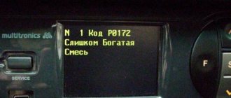
P0172 - code
DK1 shows an excessive amount of fuel residue in the exhaust system. There is a malfunction or incorrect setting of the mixture formation system. Check the injector and pressure lines.
P0351 - code
In parallel with the appearance of the error, the car’s power plant may lose power. Look for a problem on the car's ignition coil.
Code P0335
The crankshaft position sensor A circuit is faulty. Check the wires for damage or oxidation of the contact groups.
Breakdown P0420
The catalytic converter's flow rate is below the set threshold. The system requires cleaning or complete replacement.
Error P0500 Camry
The car's speedometer is not working correctly. The sensor is damaged or shorted. The instrument needle may float, not start, or freeze in one position.
Error P1135 V30
Mixture composition sensor – no heating. The heating element is damaged or not working properly.
P1604 - error V50
Failure to start the power plant. A more thorough diagnosis is required.
Error P1660
The intake manifold geometry change drive is not working correctly or the sensor is transmitting incorrect data. Check the system for dirt or carbon deposits.
P2109 - error
The throttle valve is not functioning properly. Usually the problem is simple dirt stuck to the internal parts of the device.
P2238 code
Low signal level of the positive circuit of the oxygen sensor. There may be two problems here.
- Problems with the settings of on-board systems.
- Problems with the sensor or its wiring.
P2716 - error
The code indicates an electrical problem with the oil pressure control valve inside the automatic transmission. Check wiring components for damage.
P2714 - error
The PCM system produces a similar signal when the pressure control valve D is faulty or stuck in the off position. Fires at the same time as code U660E.
To perform repairs, clean the mechanical part of the sensor or completely replace it.
Camry Error V40: Check VSC System
The problem occurs on cars with diesel power plants. Check the fuel system for damage. It may also turn out that the tank is filled with low-quality fuel or with foreign impurities.
Climate control errors
Older versions of the car are not subject to installation problems. With the complication of the design of the unit and the integration of an advanced air conditioner, the shortcomings of the module began to appear.
If there are problems, it is recommended to show the car to specialists.
Camry charging system malfunction 55 error
Charging failure is accompanied by the appearance of a battery-shaped light on the dashboard. If it is not possible to perform thorough computer diagnostics, it is recommended to check the following areas:
- generator wiring;
- voltage regulator;
- serviceability of the battery itself.
Automatic transmission errors
If the machine breaks down, do not try to fix the situation yourself. An automatic transmission is a complex mechanism consisting of many components. It is not recommended to get into the module without knowledge of the device and the principle of repair.
Error: Check Sonar
There are problems with the parking sensors system. The device should be thoroughly diagnosed or sensitive parts of the sensor should be replaced.
ABS errors
Installed on cars since 1996. The module reports faults related to sensors or their wiring. The sensors are installed in places exposed to dirt and road chemicals.
P0351, P0352, P0353, P0354, P0355, P0356
Ignition coil errors, the last two can only appear on Toyota V6 engines, for example, 2GR-FE. Reasons for these codes:
- faulty ignition coil,
- faulty wiring leading to the coils,
- broken electronic control unit.
To accurately determine the malfunction, use an oscilloscope to measure the electrical signal from the ignition coil that showed the error. If you don't have an oscilloscope, you can swap the potentially faulty coil with another. For example, there is an error P0351, we moved the coil from the first cylinder to the second, now the scanner shows P0352 - the problem is in the coil, but if the code remains the same P0351 - the wiring or ECU is faulty.
Airbag fault codes
If there is a message on the dashboard about a malfunction of the airbag system, you should definitely check which elements and sensors are faulty or there is no communication with them. The resistance of the airbag and belt pretensioner squib can be checked with a multimeter, it is about 2 ohms. Error codes with explanations are given in the table.
P0172
Error P0172 - Air/fuel mixture too rich. Causes:
- air intake system,
- faulty injectors,
- not working correctly mass air flow sensor,
- fuel pressure is outside acceptable limits,
- exhaust gas leak,
- the problem is in the circuit or in the oxygen sensor itself,
- ECU.
To make an accurate diagnosis, contact an experienced specialist. One option to eliminate the error is to replace the VVT-I valve.
P2237
P2237 – open circuit in the oxygen sensor (A/F) pumping current circuit, P2238 – low current in the oxygen sensor (A/F) pumping current circuit (1 row 1). We are talking about a lambda probe installed before the catalyst, which is located next to the engine. This error may not affect the behavior of the car, but fuel consumption will increase. We would like to warn against replacing this sensor with a non-original one.
The lambda probe, located before the catalyst near the engine, is replaced only with the original one. The second sensor installed after the catalytic converter can be replaced with a universal one. Using this head will allow you not to remove the heat shield when replacing failed lambda probes.
Engine error codes, possible malfunction
After performing diagnostic work, it is necessary to obtain as much information as possible about the suspected malfunction. For example, computer diagnostics showed error P0032. According to the table below, it is interpreted as exceeding the maximum current in the heater circuit of the first lambda probe. You should not immediately buy a new sensor (in Camry it costs more than 3,000 rubles).
First of all, you need to check the electrical wiring that leads to it. The Camry, like most new gasoline cars, has two oxygen sensors (lambda probes) - one before and one after the catalyst. They are heated, that is, there is a spiral that heats the sensor to enter working condition. It is possible that the sensor is faulty, the coil is shorted, and the diagnostics shows error 0032. But in most cases, the cause of this malfunction is a short circuit in the wiring leading to the lambda probe. It is laid in close proximity to the exhaust manifold, which heats up to a temperature of more than 300 degrees Celsius. If the PVC insulation is destroyed, the wiring may have a short to ground on the vehicle. In this case, error P0032 may appear. It is possible that the error will disappear at the time of diagnosis, but then it will appear again while driving, so it is better to check the quality of the insulation.
Below is a breakdown of the main engine error codes and their possible causes.
P0137, P0157
P0137, P0157 – low voltage in the oxygen sensor circuit (bank 1, bank 2 sensor 2). Causes of errors P0137, P0157:
- open circuit, break in the heated oxygen sensor circuit, row 1,2 sensor 2,
- faulty lambda probe (heated oxygen sensor),
- air/fuel mixture sensor bank 1,2 sensor 1,
- leakage from the exhaust gas system.
New and Old Lambda Sensor If, during active air-fuel ratio control, the target ratio is rich but the heated oxygen sensor output voltage is less than 0.21 V (lean), the ECM treats this as an excessively low sensor output voltage and sets DTC P0137 or P0157 . During active air-fuel ratio control, if the target ratio is lean but the output voltage is greater than 0.59 V (rich), the ECM considers this to be an excessively high sensor output voltage and sets DTC P0138 or P0158.
If replacing the sensor did not bring results, then the technicians could have replaced the wrong sensor (this happens often), or the problem is not in the sensor, but in the circuit or in an exhaust gas leak. Check all connectors; they may have oxidized or moisture may have gotten into them. Visually inspect the wiring to see if its integrity is damaged. If the circuit is visually in order, then check its operation using an oscilloscope.
Catalog number 1 of the oxygen sensor installed before the catalyst.
Video
Toyota Camry error codesLink to main publication
| Code 1 – 1 flash, pause, 1 flash | No faults | |
| Code 12 – 1 flash, pause, 2 flashes | The NE signal does not arrive to the ECM within a few seconds after the engine starts. The G signal does not arrive to the ECU at engine speeds from 500 to 4000 rpm. | Electrical circuit of the ignition distributor. Distributor. |
Ignition unit. Electrical circuit of the ignition unit. Starter electrical circuit. ECM block.
Fault codes for gasoline engines (Toyota)————————————————————————————Self-diagnosis codes are read by the number of flashes of the “CHECK ENGINE” indicator when the “TE1” terminals are closed ”-“E1” connector DLC1 under the hood or “TC”-“CG” connector DLC3 under the dashboard and the ignition is on.12 - Crankshaft position sensor (P0335)13 - Crankshaft position sensor (P0335, P1335)14 - Ignition system , coil No. 1 (P1300) and No. 4 (P1315)15 - Ignition system, coil No. 2 (P1305) and No. 3 (P1310)16 - Automatic transmission control system18 - VVT-i system - phases (P1346)19 - Pedal position sensor accelerator (P1120)19 - Accelerator pedal position sensor (P1121)21 - Oxygen sensor (P0135)22 - Coolant temperature sensor (P0115)24 - Intake air temperature sensor (P0110)25 - Oxygen sensor - lean signal (P0171) 27 - Oxygen sensor No. 231 - Absolute pressure sensor (P0105, P0106)34 - Turbocharging system35 - Turbo pressure sensor36 - CPS sensor (P1105)39 - VVT-i system (P1656)41 - Throttle position sensor (P0120, P0121)42 — Vehicle speed sensor (P0500)43 — Starter signal47 — Additional throttle position sensor49 — Fuel pressure sensor (D-4) (P0190, P0191)51 — Switch status52 — Knock sensor (P0325)53 — Knock signal55 — Knock sensor No. 258 — SCV drive (D-4) (P1415, P1416, P1653)59 — VVT-i signal (P1349)71 — EGR system (P0401, P0403)78 — Injection pump (D-4)89 — ETCS drive (P1125, P1126, P1127, P1128, P1129, P1633)92 - Cold start injector (D-4) (P1210)97 - Injectors (D-4) (P1215) Fault codes for diesel engines (Toyota)——————————— ———————————————–12 — Crankshaft position sensor13 — Speed sensor14 — Injection advance angle adjustment valve15 — Throttle valve servomotor17 — Control unit signal18 — Electromagnetic bypass valve19 — Accelerator pedal position sensor22 — Coolant temperature sensor24 — Intake air temperature sensor32 — Correction resistors35 — Boost pressure sensor39 — Fuel temperature sensor42 — Vehicle speed sensor96 — EGR valve position sensor Automatic transmission fault codes (Toyota)——————————————— ———————————–Self-diagnosis codes are read by the number of flashes of the “O/D OFF” indicator when the “TE1”-“E1” terminals of the DLC1 connector under the hood or “TC”-“CG” of the DLC3 connector under the hood are closed instrument panel and the ignition is on (in this case, overdrive must be allowed - “O/D OFF” is not lit).11 - Normal37 - Automatic transmission input shaft speed sensor (P1705)38 - Automatic transmission fluid temperature sensor42 - Speed sensor (or output shaft speed sensor) (P0500)44 - Speed sensor (or rear output shaft speed sensor)46 - Accumulator pressure control solenoid (P1765)61 - Speed sensor (or front output shaft speed sensor)62 - Solenoid No. 1 ( P0753)63 — Solenoid No. 2 (P0758)64 — Torque converter lockup clutch solenoid (P0773)67 — Automatic transmission input shaft speed sensor68 — Torque converter lockup clutch control solenoid73 — Center differential lockup clutch solenoid ABS fault codes (Toyota)—————— —————————————————————Reading codes (models with DLC1 connector)— Turn on the ignition.— Jumper the “TC” and “E1” terminals of the DLC1 connector.— Remove the jumper from pins “WA” and “WB” of connector DLC1.— After 4 seconds, read the code by the number of indicator flashes.— Remove the jumper from pins “TC” and “E1.”
— Install a jumper on pins “WA” and “WB”.
Resetting codes (models with DLC1 connector)— Turn on the ignition.— Jumper the “TC” and “E1” terminals of the DLC1 connector (vehicle stationary).— Press the brake pedal eight or more times in an interval of three seconds.— The indicator should display the normal code ( blink 2 times per second).— Turn off the ignition.— Remove the jumper from the “TC” and “E1” terminals.
— Make sure the ABS indicator goes out. Reading codes (models with DLC3 connector)—Jump the “TC” and “CG” terminals of the DLC3 connector.—Turn on the ignition.—After 4 seconds, read the code by the number of indicator flashes.
— Remove the jumper from the “TC” and “CG” terminals. Resetting codes (models with DLC3 connector)— Jumper the “TC” and “CG” terminals of the DLC3 connector. — Turn on the ignition.
— Press the brake pedal eight or more times within an interval of three seconds. — The indicator should display the norm code (blink 2 times per second).
— Remove the jumper from the “TC” and “CG” terminals.
Code System11 Open circuit in the solenoid valve relay12 Short circuit in the solenoid valve relay circuit13 Open circuit in the electric pump relay circuit14 Short circuit in the electric pump relay circuit21 Open circuit or short circuit in the front right wheel solenoid valve22 Open or short circuit in the front left solenoid valve wheels23 Open circuit or short circuit in the rear right (left) wheel solenoid valve24 Open circuit or short circuit in the rear left (right) wheel solenoid valve31 Malfunction of the front right wheel speed sensor32 Malfunction of the front left wheel speed sensor33 Malfunction of the rear rotation speed sensor right wheel34 Malfunction of the rear left wheel speed sensor41 Battery voltage is too high or too low43 Malfunction in the deceleration sensor circuit44 Open or short circuit in the deceleration sensor circuit49 Open in the brake light switch circuit51 Short circuit or open circuit in the electric pump power supply circuit71 Low signal level from the frequency sensor rotation of the front right wheel72 Low signal level from the front left wheel speed sensor73 Low signal level from the rear right wheel speed sensor74 Low signal level from the rear left wheel speed sensor75 Incorrect signal change from the front right wheel speed sensor76 Incorrect signal change from the speed sensor rotation of the front left wheel77 Incorrect change in the signal from the rear right wheel speed sensor78 Incorrect change in the signal from the rear left wheel speed sensor79 Malfunction of the deceleration sensor98 - Vacuum sensor in the vacuum brake booster (C1200 SRS fault codes (Toyota)————————— —————————————————–Self-diagnosis codes are read similarly to others, by the number of flashes of the “SRS” indicator when the “TC”-“E1” terminals of the DLC1 connector under the hood or “TC”- are closed. “CG” of the DLC3 connector under the dashboard and the ignition is on.
Codes should be erased when the ignition is turned off. If the codes are stored, it is necessary to carry out the cleaning procedure: - connect two wires to the “TC” and “AB” terminals - turn on the ignition and wait at least 6 seconds - alternately, once a second, short the “TC” and “AB” terminals to ground ( pause between closures - less than 0.2 seconds) - after the third closure of the “TC” output, the indicator should flash at a high frequency - this means the codes are erased.
11 — Driver air protection igniter (short to ground)12 — Driver air protection igniter (short to power)13 — Driver air protection igniter (short circuit)14 — Driver air protection igniter (open circuit)15 — Front right SRS sensor (short or open) in the circuit)15 - Front right SRS sensor (short to ground or power)16 - Front left SRS sensor (short or open circuit)16 - Front left SRS sensor (short to ground or power)31 - Malfunction of the SRS control unit51 - Igniter Passenger CB (short to ground)52 - Passenger CB igniter (short to power)53 - Passenger CB igniter (short circuit)54 - Passenger CB igniter (open circuit)61 - Driver belt pretensioner igniter (short to ground)62 - Driver belt pretensioner igniter (short to power)63 - Driver belt pretensioner igniter (short circuit)64 - Driver belt pretensioner igniter (open circuit)71 - Passenger belt pretensioner igniter (short to ground)72 - Passenger belt pretensioner igniter (short circuit) to power supply) 73 — Passenger belt pretensioner igniter (short circuit) 74 — Passenger belt pretensioner igniter (open circuit) 4WS system fault codes (Toyota)—————————————————— ————————–Self-diagnosis codes are read by the number of flashes of the “4WS” indicator when the “TC”-“E1” terminals of the DLC1 connector under the hood are closed and the ignition is on.
Code System - -11 Electronic control unit 4WS12 Malfunction of the main electric motor of the rear steering gear13 Malfunction of the steering gear control drive21 Short circuit in the main electric motor system22 Open circuit in the main electric motor system23 Blocking of the main electric motor24 Malfunction of the main electric motor31 Open circuit in the reverse motor system32 Malfunction of the electric motor reverse gear41 Malfunction of the left front wheel speed sensor42 Malfunction of the 4WS system sensor43 Incorrect operation of the 4WS system sensor
Checking the airbag system indicator Set the ignition switch to the “ACC” or “ON” position, check that the warning light comes on and goes off after about 6 seconds. Note: If the ignition switch is in the “ACC” or “ON” position and the indicator remains on or flashes, check the fault code. If the indicator sometimes lights up or remains on even when the ignition switch is in the “OFF” position, check the indicator circuit for a short circuit .
Mechanism to prevent activation of the SRS system.
1. Set the ignition switch to the “ACC” or “ON” position and wait approximately 20 seconds. 2.
Install a jumper on terminals “TC” and “E” of the diagnostic connector. Note: Incorrect pin connections may result in system failure.
3, If there is no fault, the indicator will flash 2 times per second.
4. If there is a malfunction, the indicator will flash at a variable frequency. Identify trouble codes.
. The figure shows an example of the output of codes “11” and “31”.
5. Fault codes are displayed from the smallest. If codes are not output, check the “TC” output circuit of the diagnostic connector.
6. For decoding of fault codes, see the table “SRS system fault codes”.
where is the OBD 2 diagnostic connector located in the Camry 40 (year) – Toyota Camry club Russia – AvtoVyzov
Self-diagnosis of Toyota Camry ACV40 via diagnostic connector.
0:112
Self-diagnosis process for all Toyota vehicles
0:243
Connector type No. 1 is a 20-pin rectangular DLC No. 1 connector. Location: under the hood. Typically closed with a “DIAGNOSIS” lid
0:473
1:978
20-pin rectangular connector.
1:1051
FP - Output for measuring or supplying voltage to the fuel pump without starting the engine. Set the jumper to “B” and “FP”. When you turn on the ignition, the fuel pump will start immediately.
1:1363
W — Output of the “Check Engine” light. Connecting a very low power indicator light between “B” and “W” duplicates the “Check Engine” light (on the instrument panel). E1 - This is “ground” (Earth) TE1 - Output for reading codes of the EFI system (Normal mode) TE2 - Output for reading codes of the EFI system (Test mode) TC - Used to read self-diagnosis codes of additional devices of the vehicle (Bridge " TC" and "E1" in the connector causes the codes to be indicated by the light "ABS", "SRS", "TRC OFF" and "Height Control"). OP2 - K-diagnostic line B - 12V power supply from the battery (appears when the ignition is turned on) VF1 - “VF-feedback voltage” - contact, the voltage at which is the result of a computer analysis of the state and performance of the lambda probe, as well as for indicating the mode in where the injection system is located. Sometimes the output voltage is output to “CCO” VF2 – Similar to “VF1”, but for the second lambda probe OX – Control of the output voltage of the lambda probe (oxygen sensor) OX2 – Similar to “OX1”, but for the second lambda probe CC2 – Used for diagnostics of the second TS lambda probe - Designed to read self-diagnosis codes (checking voltage deviations) of the “ABS” and “Traction Control System” speed sensors, which cannot be detected by conventional self-diagnosis. TT — Used to diagnose automatic transmission OP3 — “L” diagnostic line TD — Used to disable the “Air Suspension System” (air suspension (for example, in LS400)) OP1 — Used to read immobilizer self-diagnosis codes IG- — Ground (switch output — for remote tachometer) AB - Erasing fault codes “SRS” Note: On cars with OBD-II for the domestic Japanese market, DLC connector No. 1 is installed, but it does not have contacts “TE1”, “TE2”, “W”, “VF”, “CCO”, “OX”, “IG-”
Connector type No. 2 - 17-pin semicircular DLC connector No. 2. Location: under the hood. As a rule, it is closed with a lid. The designations are the same as in DLC connector No. 1.
1:46541:9
2:514
17-pin rectangular connector.
2:587
Connector type No. 3 - 16-pin OBD-II or DLC connector No. 3. Location: in the cabin under the dashboard on the driver's side.
2:796
3:1301
OBD2 connector.
3:1323
1,3,8,9,11,12 — Factory option 2 — J1850 Bus 4 — Body ground (CG) 5 — Signal ground 6 — CAN-High line, J-2284 7 — K-line diagnostics (ISO 9141-2 and ISO/DIS 14230-4) 10 - J1850 Bus - 13 - TC - Timing Check - Output for disabling SPD adjustment to check the base angle or output for reading slow ABS self-diagnosis codes 14 - CAN-Low line, J-2284 15 - L - diagnostic line (ISO 9141-2 and ISO/DIS 14230-4) 16 - 12V power supply from the battery Diagnostic connector contacts for the protocols used. Pins = 4, 5, 7, 15, 16 - ISO 9141-2. Pins = 2, 4, 5, 10, 16 - J1850 PWM. Pins = 2, 4, 5, 16 (minus 10) - J1850 VPW. All three data exchange protocols operate via a standard OBD-II J1962 connector cable. Now let's proceed to the diagnosis itself. Before diagnostics, check: 1. Battery voltage is not lower than 11V. 2. The throttle valve is in the closed position. 3. All auxiliary equipment (radio, climate control, parking sensors, etc.) is turned off. For diagnostics, we need a jumper made from a piece of wire, a paper clip, wire, etc.
CHAPTER 1. Diagnostic process for Toyota Camry with OBD-II connector (DLC No. 1):
1. Turn the ignition OFF. 2. Bridge contacts “4” and “13” (with a paper clip, wire, wire).
3:3385
4:504
It is necessary to jumper pins 4 and 13
4:574
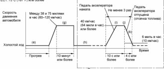
3. Turn the key to the “ON” position, but do not start the engine! 4. Read the code (two-digit number) by the number of light bulb flashes (~4 seconds after switching on). 1st digit of error. Equal to the number of flashes with an interval of ~0.5 seconds. Afterwards there is a pause of ~1.5 seconds. 2nd digit of error. Equal to the number of flashes with an interval of ~0.5 seconds. Pause between different codes ~2.5 sec. After all codes are issued, there is a pause of ~4.5 seconds. and the issuance of codes is resumed. If there are no errors, then the interval between flashes will be ~0.25 seconds.
4:1482
5:1987
As an example, the figure below shows the flashing patterns of the ABS and VSC warning lamps (for models without a multi-information display) for the system normal code and fault codes 11 and 21, as well as the display of trouble code 32 for VSC on the multi-information display (for models with a multi-information display ).
5:2589
Note: Look at all lights. For example, if there are errors in the ABS system, then this lamp will show the error code. The on-board computer can also report diagnostic results (for example, “DIAG VSC 21” or “VSC DIAG OK” if there are no errors). There are cases when the codes read from the light bulbs do not match those issued by the on-board computer. This situation can occur when there are problems with the “brains” (ECM/PCM/ECU). 5. Turn the ignition OFF. 6. Remove the jumper from pins “4” and “13”. Resetting codes: 1. Turn the ignition OFF. 2. Bridge contacts “4” and “13” (with a paper clip, wire, wire). 3. Turn the key to the “ON” position, but do not start the engine! 4. Press the brake pedal 8 or more times in an interval of ~3 seconds. 5. The indicator that generated the error should display a normal code (the interval between flashes will be ~0.25 seconds). There may still be errors that are currently malfunctioning. 6. Turn the ignition OFF. 7. Remove the jumper from pins “4” and “13”. Interpretation of two-digit codes: ABS codes 11 - (C0278) Open or short circuit in the ABS solenoid valve relay circuit 12 - ? 13 - (C0273) Open or short circuit in the ABS motor relay circuit * 21 - (C0200) Solenoid valve circuit SFR 22 - (C0236) Solenoid valve circuit SFL 23 - (C0246) Solenoid valve circuit SRR 24 - (C0256) Solenoid valve circuit SRL 25 - (C1225) Solenoid valve circuit SMC 26 - (C1226) Solenoid valve circuit SMC 27 - (C1227) Solenoid valve circuit SRC 28 - (C1228) Solenoid valve circuit SRC 31 - (C0200) Right front speed sensor * 32 - ( C0205) Left front speed sensor* 33 — (C0210) Right rear speed sensor* 34 — (C0215) Right rear speed sensor* 35 — (C1330) Right front speed sensor circuit 36 — (C1331) Left front speed sensor circuit 37 — ( C1237) Tires of different sizes. Speed Sensor Rotor Malfunction 38 - (C1332) Right Rear Speed Sensor Circuit 39 - (C1333) Right Rear Speed Sensor Circuit 41 - (C1241) Low or Excessive Battery Positive Voltage 46 - (C1246) Master Cylinder Pressure Sensor Malfunction* 49 - (C1249) Open in the brake light switch circuit 58 - (C1249) Stop light switch circuit 62 - (C1300) Malfunction of the skid control ECU 88 - (C1288) ECU version mismatch 94 - (U0073) Control unit data bus disconnected
Error code: Peugeot and Citroen diagnostic programs for the ELM327 scanner in Russian
5:4252
Even after troubleshooting, the ABS warning light will turn off only after performing the following operations: *: Option #1: Drive the vehicle at 20 km/h (12 mph) for 30 seconds and check that the ABS warning light goes off. Reset the error code. Option #2: Stop the car for 5 seconds or more and lightly press the brake pedal 2-3 times. When driving the vehicle at a speed of 50 km/h (31 mph), press the brake pedal firmly for approximately 3 seconds. Repeat this operation at least 3 times and make sure that the ABS warning light goes off. Reset the error code.
5:1118
VSC Codes 25 - (C1225) SMC Solenoid Circuit 26 - (C1226) SMC Solenoid Circuit 27 - (C1227) SRC Solenoid Circuit 28 - (C1228) SRC Solenoid Circuit 28 - (C0365) Retardation Sensor 31 Malfunction - (C1231) ) Malfunction in the steering angle sensor circuit 34 - (C1234) Malfunction of the yaw rate sensor 42 - (C1301) Malfunction of the multiplex CAN bus (steering wheel angle sensor circuit, yaw rate and deceleration sensor circuit) 43 - (C0200) Malfunction of the deceleration sensor (combined with yaw rate sensor). ABS control system malfunction 44 - (C1224) NE signal circuit 45 - (C1201) Engine control system malfunction 51 - (C1350) Pump motor blocked/open in pump motor ground circuit 51 - (C1201) Engine control system malfunction 53 - (C1246) Malfunction of the master cylinder pressure sensor 54 - (C1208) Malfunction of the steering angle sensor 55 - (C0236) Open or short circuit in the yaw rate sensor circuit 59 - (C1203) Malfunction in the data bus of the engine ECU 62 - ( U0123) Lost communication with yaw rate sensor 63 - (U0126) Lost communication with steering angle sensor 65 - (U0100) Lost communication with ECM/PCM/ECU 88 - (C1288) Incompatibility of ECU version
CHAPTER 2. Diagnostic process for Toyota cars with OBD-I connector (DLC No. 2-3):
Diagnosis of ABS faults: Used to read self-diagnosis codes for additional vehicle devices (Bridging “TC” and “E1” in the connector causes the codes to be indicated by the ABS, SRS, TRC OFF and Hight control light). 1. Turn the ignition OFF. 2. Bridge contacts “TC” and “E1” (with a paper clip, wire, wire). 3. Turn the key to the “ON” position, but do not start the engine! 4. Remove the jumper from pins “WA” and “WB”. 5. Read the code (two-digit number) by the number of light bulb flashes (~4 seconds after switching on). 6. Turn the ignition OFF. 7. Remove the jumper from pins “TC” and “E1”. 8. Place a jumper on pins “WA” and “WB”.
5:4695
Resetting ABS codes: 1. Turn the ignition OFF. 2. Bridge contacts “TC” and “E1” (with a paper clip, wire, wire). 3. Turn the key to the “ON” position, but do not start the engine! 4. Press the brake pedal 8 times in an interval of 3 seconds. 5. The indicator should display the norm code (blink 2 times per second). 6. Turn the ignition OFF. 7. Remove the jumper from pins “TC” and “E1”. 8. Make sure the ABS indicator goes off.
SRS self-diagnosis codes (airbags): They are read similarly to others - by the number of flashes of the “SRS” indicator when the “TC” - “E1” terminals are closed.
5:968
Clearing SRS fault codes: 1. Turn the ignition OFF. 2. Bridge contacts “TC” and “AB” (with a paper clip, wire, wire). 3. Turn the key to the “ON” position, but do not start the engine (wait at least 6 seconds). 4. Alternately, with an interval of 1 second, connect terminals “TC” and “AB” to ground. 5. After the 3rd short circuit of the “TC” output, the indicator should blink at a high frequency - this means the codes are erased. 6. Turn the ignition OFF. 7. Remove the jumper from terminals “TC” and “AB”. Never clear the airbag system fault code without checking and finding out the cause of the error!
Reading EFI system codes. Diagnostics: “Normal mode”. 1. Turn the ignition OFF. 2. Bridge the contacts “TE1” and “E1” (In “old” systems “T” or “TE”) with a paper clip, wire, or wire. 3. Turn the key to the “ON” position, but do not start the engine! 4. Read the code (two-digit number) by the number of flashes of the “CHECK” light (light with an image of the engine, also known as “MIL”) after ~4 seconds. after switching on. Codes can also be read by connecting the LED to “W”. 5. Turn the ignition OFF. 6. Remove the jumper from terminals “TE” and “E1”.
5:2889
Reading EFI system codes. Diagnostics: “Test mode”. (Resetting codes is the same as ABS) 1. Turn the ignition OFF. 2. Bridge contacts “TE2” and “E1” with a paper clip, wire, or wire. 3. After this, the car should travel approximately 15 km. 4. After stopping, do not turn off the engine and, while idling, connect contacts “TE1” and “E1” (“TE2” and “E1” do not open!). 5. Read the codes. 6. Remove the jumpers in reverse order (“TE1” and “E1” => “TE2” and “E1”).
Toyota tire pressure monitoring system: Codes are read in the standard way by the number of flashes of the indicator when the ignition is on and the “TC” and “E1” terminals are closed. Removing codes is similar to deleting ABS system codes.
5:1202
Resetting the Toyota tire pressure monitoring system: Resetting the tire pressure monitoring system and its preliminary adjustment must be done after performing any work related to replacing wheels, tires or rims (the pressure in all 4 wheels must be correctly adjusted). For Toyota vehicles without an installation button: 1. Turn the ignition OFF. 2. Bridge contacts “TS” and “E1” (with a paper clip, wire, wire). 3. Turn the key to the “ON” position, but do not start the engine! 4. After 30 seconds, press and hold the brake pedal until the system indicator flashes 3 times at 2 second intervals. 5. Turn the ignition OFF. 6. Remove the jumper from pins “TS” and “E1”.
5:2416
For Toyota cars with an installation button (The installation buttons have a characteristic shape and location - at the bottom of the instrument panel on the driver's side): 1. Turn the ignition OFF. 2. Bridge contacts “TS” and “E1” (with a paper clip, wire, wire). 3. Turn the key to the “ON” position, but do not start the engine! 4. Press and hold the installation button until the system indicator flashes 3 times. 5. After this, for the system to save the correct settings, you need to drive a certain distance. 6. Turn the ignition OFF. 7. Remove the jumper from pins “TS” and “E1”. Error codes: Trouble codes for Toyota gasoline engines: 12 - Crankshaft position sensor (P0335) 13 - Crankshaft position sensor (P0335, P1335) 14 - Ignition system, coil No. 1 (P1300) and No. 4 (P1315) 15 - Ignition system , coil No. 2 (P1305) and No. 3 (P1310) 16 - Automatic transmission control system 18 - VVT-i system - phases (P1346) 19 - Accelerator pedal position sensor (P1120) 19 - Accelerator pedal position sensor (P1121) 21 - Oxygen sensor (P0135) 22 - Coolant temperature sensor (P0115) 24 - Intake air temperature sensor (P0110) 25 - Oxygen sensor - lean mixture signal (P0171) 27 - Oxygen sensor No. 2 31 - Absolute pressure sensor (P0105, P0106) 34 - Turbocharging system 35 - Turbo pressure sensor 36 - CPS sensor (P1105) 39 - VVT-i system (P1656) 41 - Throttle position sensor (P0120, P0121) 42 - Vehicle speed sensor (P0500) 43 - Starter signal 47 - Auxiliary Throttle Position Sensor 49 - Fuel Pressure Sensor (D-4) (P0190, P0191) 51 - Switch Status 52 - Knock Sensor (P0325) 53 - Knock Signal 55 - Knock Sensor No. 2 58 - SCV Actuator (D-4) (P1415, P1416, P1653) 59 - VVT-i signal (P1349) 71 - EGR system (P0401, P0403) 78 - Injection pump (D-4) 89 - ETCS drive (P1125, P1126, P1127, P1128, P1129, P1633) 92 - Cold start injector (D-4) (P1210) 97 - Injectors (D-4) (P1215) 98 - Brake booster vacuum sensor (C1200)
5:3409
Fault codes for Toyota diesel engines: 12 - Crankshaft position sensor 13 - Speed sensor 14 - Injection advance angle adjustment valve 15 - Throttle valve servo 17 - Control unit signal 18 - Electromagnetic bypass valve 19 - Accelerator pedal position sensor 22 - Coolant temperature sensor fluid 24 — Intake air temperature sensor 32 — Correction resistors 33 — Throttle valve actuator 35 — Boost pressure sensor 39 — Fuel temperature sensor 42 — Vehicle speed sensor 47 — Throttle position sensor 89 — ECU (IC) 96 — EGR valve position sensor
5:1193
Automatic transmission fault codes: Self-diagnosis codes are read by the number of flashes of the “O/D OFF” indicator when the “TE1”-“E1” terminals are closed, and the overdrive must be turned on. 11 - Normal 37 - Automatic transmission input shaft speed sensor (P1705) 38 - Automatic transmission fluid temperature sensor 42 - Speed sensor (or output shaft speed sensor) (P0500) 44 - Speed sensor (or rear output shaft speed sensor) 46 — Accumulator pressure control solenoid (P1765) 61 — Speed sensor (or front output shaft speed sensor) 62 — Solenoid No. 1 (P0753) 63 — Solenoid No. 2 (P0758) 64 — Torque converter lock-up clutch solenoid (P0773) 67 — Frequency sensor rotation of the automatic transmission input shaft 68 — Torque converter lock-up clutch control solenoid 73 — Center differential lock-up clutch solenoid
Error code: The best programs for the ELM327 car scanner: Carista, MotorData and others
5:2710
6:504
Process: 1. Stop the engine. 2. Simultaneously press and hold the “AUTO” and “Internal air circulation” buttons on the climate control. 3. Turn on the ignition. After checking the indicators, sensor diagnostics will automatically begin. 4. The result of the sensor diagnostics is displayed in the window displaying the set temperature. If there are 2 or more codes, the display starts with the smallest one. 5. To diagnose the drives, press the “Internal air circulation” button. Checking the drives should be carried out on a warm engine. To slow down the test, press the heated front window button. At intervals of 1 second. the damper actuators, fan and relay will operate. To enter the sensor diagnostic mode, press “AUTO”. 6. To complete the diagnostics, press the “OFF” button. Clearing the memory: After troubleshooting, clear the memory: while diagnosing the sensors, press the “Heated front window” (FRONT) and “Heated rear window” (REAR) buttons simultaneously.
6:2409
7:504
Here's what you need to click to diagnose!
7:596
Error codes: 00 - No errors 11 - Interior temperature sensor* 12 - Ambient temperature sensor* 13 - Evaporator temperature sensor* 14 - Coolant temperature sensor* 21 - Sunlight sensor (passenger side)* 22 - Lock sensor compressor** 23 — Pressure sensor (refrigerant).*** 24 — Sunlight sensor (driver's side)* 31 — Air mixture damper position sensor (passenger's side)* 32 — Air intake damper position sensor* 33 — Air Outlet Damper Position Sensor Circuit 41 - Damper Control Servo (Passenger Side)* 42 - Damper Control Servo* 43 - Air Outlet Damper Control Servo Motor Circuit 46 - Damper Control Servo (Driver Side) 51 - Compressor Solenoid Circuit 62 - Humidity Sensor air (not in Camry) 71 - A/C Inverter High Voltage Power Resource System Malfunction 72 - A/C Inverter High Voltage Output System Malfunction 73 - A/C Inverter Start-up Signal System Malfunction 75 - A/C Inverter Cooling / Heating System Malfunction 76 - A/C Inverter Load System Malfunction 77 - A/C Inverter Low Voltage Power Resource System Malfunction 97 - BUS IC Communication Malfunction 98 - Communication Malfunction (A/C Inverter Local) 99 - Multiplex Communication Circuit Note: *: Malfunction this sensor or climate control control unit; The wiring or connectors between this sensor and the climate control are damaged. **: This sensor or climate control unit is faulty; The wiring or connectors between this sensor and the climate control are damaged; The compressor drive belt is damaged or not adjusted; The compressor electromagnetic clutch sensor is faulty; The air conditioning compressor is faulty (or the compressor is blocked); The engine control module (ECM) is faulty. ***: This sensor or climate control control unit is faulty; The wiring or connectors between this sensor and the climate control are damaged; The compressor is faulty (or the compressor is blocked); Leakage, lack of refrigerant or incorrect (lower or higher than normal) pressure in the system.
Codes 21 and 24 can pop up if diagnostics are carried out in a dark room or at night. Due to loss of connection with the instrument panel, code 71 cannot be displayed on it.
What is “compressor blocking”? Many people do not understand this point. The principle of correct operation is simple. When the compressor is OFF, the accessory drive belt rotates only the accessory drive belt pulley. If the compressor needs to be turned ON, the electromagnetic clutch is activated (the compressor is locked with the pulley and begins to rotate). The brain receives a signal from a sensor (similar to the ABS sensor) that the compressor is turned on and rotating. This sensor then transmits pulses to the ECM equal to the engine speed. If the ratio between the compressor and engine speeds deviates by 20% or more from normal operation, the ECM turns off the air conditioning compressor and the indicator begins to flash with a period of ~1 s. Data on the operating status of the compressor is transmitted by the ECM to the air conditioning control unit via a multiplex data transmission system (CAN and BEAN buses).
7:6143
https://www.obd.ru/l/7257560/, https://www.obd.ru/l/5731494/
7:6949357