The distributor is also known as the ignition distributor. The purpose of this engine mechanism is to distribute sparks among the cylinders of gasoline internal combustion engines. Other engines are characterized by a different principle of spark formation, so these engines do not need such a mechanism.
Modern electronically controlled gasoline power plants are also not equipped with an ignition distributor, since the moment of spark formation in such engines is determined by the program, and each spark plug is equipped with its own coil, so there is no need for voltage distribution.
The principle of operation of the ignition coil
The design of a conventional ignition coil is similar to that of a transformer. The ignition coil is designed to create high voltage from low voltage. It consists of an iron core (magnetic core), a primary winding, a secondary winding and electrical connections.
The magnetic core is designed to enhance the magnetic field. A thin secondary winding is wound around this steel core. It is made of insulated copper wire 0.05-0.1 mm thick, wound up to 50,000 times.
The primary winding is made of copper wire with a thickness of 0.6-0.9 mm and is wound on top of the secondary winding.
The resistance of the primary winding is 0.2–3.0 Ohm, the secondary winding is 5–20 kOhm. The ratio of turns of the primary and secondary windings (transformation ratio) is 1:100.
The technical design may differ depending on the application of the ignition coil. In the case of a conventional cylindrical coil, the electrical connections are designated as terminal 7 (primary terminal), terminal 11 (primary/secondary terminal) and terminal 9 (high voltage terminal).
The primary winding is connected to the secondary at pin 11. This circuit is used to simplify the production of coils. The current in the primary winding is turned on and off using a breaker (distributor) or a control unit (ECU). The amount of current is determined by the coil resistance and the voltage applied to terminal 7.
The very rapid change in current caused by the ECU (distributor) changes the magnetic field in the coil and induces a voltage pulse, which is converted into a high voltage voltage in the secondary winding. It passes through the ignition cable to the spark gap of the spark plug and ignites the fuel-air mixture in the engine.
The magnitude of the induced high voltage depends on the rate of change of the magnetic field, the number of turns of the secondary coil, and the strength of the magnetic field.
The opening voltage of the primary winding is 300 to 400 V. The high voltage on the secondary winding can reach 40 kV, depending on the ignition coil.
Causes of ignition coil malfunction
- Internal short circuits.
Overheating of the coil caused by the aging process, a faulty ignition module or a faulty output stage in the electronic control unit. - Malfunction in the supply voltage circuit. The coil charging time is increased due to the supply voltage being too low, which can lead to premature wear or overload of the ignition control unit or ECU output stages. This may be caused by faulty wiring or a dead battery.
- Mechanical damage. Damaged ignition cables, faulty valve cover gaskets, and oil leaks can damage the insulation of the coils. This leads to short circuits and therefore premature wear.
- Bad contacts. Contact resistance may increase due to moisture penetration into the primary and secondary circuits. This often happens after washing the engine.
Checking the ignition coils
There are several ways to test the ignition coil. This is replacing the faulty coil with a coil from another cylinder, checking the resistance of the coil windings, measuring the supply voltage and checking the high voltage. Let's take a closer look.
Replacing coils
Replacing the ignition coil with one from a different cylinder is the easiest way to start diagnosing and works very well on any vehicle.
In the case of a faulty ignition coil, you will usually have a misfire on a specific cylinder. Let's say you have a misfire in cylinder 3.
Simply remove another coil, for example from cylinder 2, and replace it with the coil from cylinder 3. Now, if you have a diagnostic scanner or an ELM327 adapter, you can erase OBD2 errors. If not, remember what error code you had.
Now start the car and let it run for a few minutes. If the ignition coil was indeed faulty, you will now see the error code “P0302. Misfire in cylinder 2” because the faulty coil from cylinder 3 was installed on cylinder 2. Now you need to remove the faulty coil from cylinder 2 and replace it with a new one.
If you change the coils and the misfire remains in cylinder 3, then the problem is not in the coil. In this case, there may be a problem with the ignition module, a problem with the coil connector or wire, with the spark plug, with the fuel injector, or an engine mechanical problem in that cylinder.
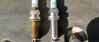
Visual inspection
Carefully inspect the coil for signs of cracks, burns, melting, or leakage currents. Check the condition of the spring inside the cap. This often indicates a problem with the coil, so check carefully.
Possible breaker failures and their symptoms
How to check the ignition coil
Repair of the distributor in the automotive industry is not carried out so often, which is due to the good reliability of this unit. Of course, there is no escape from breakdowns, but few people suffer from them. It is not so difficult to identify that it was the distributor that began to “pierce” the electric charge or grabbed another “sore”. The symptoms of malfunctions of the distributor-interrupter are specific and manifest themselves in the incorrect organization of the main functions of the device.
More precisely, possible replacement or adjustment of the distributor may be necessary if the following symptoms occur:
- the spark is gone;
- the ignition operation is upset;
- the battery stopped charging while the machine was running (not on all models);
- the car began to jerk while driving;
- Unburnt gasoline drips from the exhaust pipe.
As for specific faults, they are often represented by the following list:
- The distributor drive (rotor) has worn out or burned out. The malfunction is diagnosed through a detailed examination of the rotor and experimental verification of its correct operation. If an element breaks, it may be necessary to either install a new drive or completely replace the distributor;
- The network has broken through. This, by the way, can happen in any component of the distributor. Most often, the high-voltage wires that extend to the spark plugs from the distributor cover are affected. Other elements of the system (small wires, connectors of distributor parts, contacts, etc.) break down noticeably less often. Checking for this malfunction is carried out using a regular “ring”;
- The seals are worn out. Perhaps this is a rather rare breakdown with characteristic symptoms. To be more precise, we are talking about a general disorder of the ignition and untimely formation of a spark. For repairs, it is necessary to replace the distributor seals, and it is worth replacing not only faulty elements, but also those that work correctly, so to speak, for prevention;
- The distributor slider or the sensor responsible for distributing the charge between the spark plugs has broken. Characteristic signs of this breakdown are the inability to correctly configure the distributor or its complete failure to operate. The malfunction is eliminated by replacing the slider or sensor;
- The ignition coil has failed. This failure is characterized by either absent or incorrect sparking. Repair is carried out by replacing the burnt coil with a new one.
Other distributor malfunctions appear much less frequently. In any case, repairing this unit is not an easy task, so no motorist will be able to figure it out right away
To understand the whole essence of repairing a distributor, it is important to fully understand the principle of its operation and constantly practice. If you don’t want to learn all the basics of repair work, it’s better to entrust the repair to a professional who specializes in repairing car ignition systems
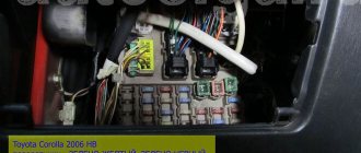
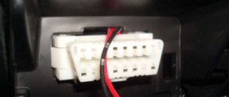
Checking the supply voltage
To check the supply voltage to the ignition coil, we will need to turn off the fuel pump. This is necessary to ensure that the engine does not start during the test. To do this, find and turn off the fuel pump fuse.
Next, disconnect the power connector from the ignition coil. We take a paper clip, make two conductors out of it and insert it into the power connector chip. We connect the multimeter, it is better to use alligator clips. Multimeter in constant voltage (DC) mode.
Now just turn on the ignition. The multimeter should show 0 volts. Next we try to start the engine, it will not start because the fuel pump is turned off. At this time, a pulsating voltage of 0-12 V will be supplied to the ignition coils. This should be displayed in the multimeter readings.
If voltage does not come to the connector, you need to check the wiring and connectors for damage and corrosion. After all measurements, reconnect the fuel pump fuse.
Once you find the faulty ignition coil, simply replace it with a new one. No additional action is required.
It's simple. If you have an old burnt, preferably badly burnt, ECU, then you need to make an artificial landscape. Or an artificial landscape. Take silicone sealant and mix it with crystalline potassium permanganate. Cast a plate with a thickness of 2 meters and an area with the ECU - burnt. He does the same with copper sulfate or, better yet, with shavings of various metals. It turns out two plates of 2 meters each. Now take yours (only your burnt ECU) and do this: put the plate with metals down above it, put the ECU microcontroller on it - burnt, and put the next manganese layer above the ECU. On the contrary, you can swap layers. You can seal the groove under the ICU contacts. So now you place a metal plate from the very top on which the ECU is attached with the ears down. That is, it’s as if you can slide a pencil under the plate like a pagoda. The very top part of the landscape design. It's simple. So now peel off the ECU cover into 4 parts with a cross and 4 quarters that cover the grooves above the contacts. And place them in the same order over the metal bottom. If you don’t want to chaff, then place it under the landscape. And from the top, take a paper packet from you and roll it in glue and put metal shavings on the glue; the bag is straightened and dried. Place it bottom to top with a muffler-filter on top. The landscape is ready. The landscape is called UMP, well, at least not UAC, that’s for sure (verified). Everyone like and like, write letters, respect the rights on the roads. Listen to nootk just AASIS!
Thank you for the important information on the impossibility of measuring resistance in the secondary winding with a high-voltage diode. It is strange that almost all Internet users claim that the secondary coil with a built-in high-voltage diode is checked in resistance measurement mode, as a result of which the resistance of the secondary coil is determined. Based on this information, I had to buy four individual coils. And in vain. Since it was not possible to determine the resistance of the secondary winding of the new coils either.
Malfunction of the contactless distributor.
When operating contactless distributors, the main malfunction is a malfunction of the hall sensor or inductive sensor. Minor wear and play in the bushings and bearing of the movable contact plate do not affect the operation of the distributor until the sensor rotor touches the stator.
Such malfunctions as breakdown of the slider, burning of its resistance. It can also break through the distributor cap between the cylinders. This malfunction is typical for non-contact distributors, since the secondary voltage in these systems is twice as high as in a contact one.
admin23/04/2011
Subscribe to comments
- Vlad — November 12th, 2012 at 12:54 pm
Good afternoon, I have a Toyota Kaldina that stopped starting, at first it failed, then I changed the explosive wires, the ignition coil, and the slider in the distributor. and it stopped starting altogether. I unscrewed the spark plug and saw a red spark and a velvety black carbon deposit on it, i.e. what a dead thing. Question There is a capacitor in the distributor and it looks worn out, sad, now I’m waiting for a new one, I ordered it. Could this be the reason, is this capacitor a noise suppressor or a spark amplifier? The on-board computer has not flashed a check more than once since the date of purchase of the car.
admin — November 12th, 2012 at 05:33 pm
It's hard to say without knowing the type of engine and year of manufacture, or at least the type of ignition. These models were equipped with four types of distributors. The capacitor plays basically the same role in all. In addition to the capacitor, the reason may be in the switch, which is also installed in the distributor. The capacitor can most likely be checked by charging it by connecting it in series to a 220V network with a lamp of no more than 100W. After disconnecting, use a screwdriver with an insulated handle to close the wire to its body. If the capacitor is working properly, a spark will jump. Answer
- Huilo Waffle - April 2nd, 2012 at 10:15 pm
Cool! It helped me! Now it doesn't bother me!!!
- Mikhail - August 26th, 2011 at 15:24
...The capacitance of the capacitor should be in the range of 15-25 mF... Should be 0.15-0.25 μF
admin — August 27th, 2011 at 0:20
Thank you for your comment. I fixed everything. Answer
A comment
Name *
Website
This site uses Akismet to reduce spam. Find out how your comment data is processed.
« Distributor device
Ignition system VAZ - 2105 »
Tags
VAZ, VAZ malfunctions Sensors Ignition Injector Devices Starter Circuits Electric cars Power supply VAZ 2110 gazelle gazelle business recorders car repair
Recent Entries
- Laser headlights.
- Advantages and disadvantages of halogen lamps
- Design and principle of operation of parking sensors
- Multifunctional device Roadgid X7 Hybrid GT
- Malfunction of the GAS ignition system
Archives
Archives Select month September 2021 August 2021 July 2019 December 2021 August 2021 July 2021 June 2021 May 2021 April 2017 March 2021 December 2021 November 2021 October 2021 September 2016 August 2021 July 202 1 June 2021 May 2021 April 2021 March 2016 February 2021 November 2015 October 2015 August 2015 July 2015 June 2015 May 2015 April 2015 March 2015 February 2015 January 2015 December 2014 November 2014 October 2014 September 2014 August 2014 July 2014 June 2014 May 2014 April 201 4 February 2014 January 2014 December 2013 November 2013 October 2013 August 2013 June 2013 May 2013 March 2013 February 2013 January 2013 November 2012 October 2012 September 2012 August 2012 July 2012 June 2012 May 2012 April 2012 March 2012 February 2012 January 2012 December 2011 November 2011 October November 2011 September 2011 August 2011 July 2011 June 2011 May 2011 April 2011
Categories
- Accumulator battery
- Video
- Generator
- Sensors
- Diagnostics
- Ignition
- News
- Equipment
- Devices
- Repair
- Spark plug
- Starter
- Scheme
- Devices
- Electric cars
- Electricity supply
Repair of distributor 4A-FE
The distributor is also known as the ignition distributor. The purpose of this engine mechanism is to distribute sparks among the cylinders of gasoline internal combustion engines. Other engines are characterized by a different principle of spark formation, so these engines do not need such a mechanism.
Modern electronically controlled gasoline power plants are also not equipped with an ignition distributor, since the moment of spark formation in such engines is determined by the program, and each spark plug is equipped with its own coil, so there is no need for voltage distribution.
- Operating principle of the ignition distributor
- Diagnostics of the electrical part of the distributor
- Mechanical part and coil
- Conclusion
Operating principle of the ignition distributor
A misfire, in simple words, is a situation in which ignition did not occur in the 4A-FE cylinder. The reason is lack of fuel or lack of spark. The worst option is the presence of fuel, but no spark. In this case, the fuel is sent to the catalyst, where it burns, melting the catalyst itself. To avoid such situations, Toyota uses the formula: no spark - no fuel.
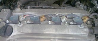
In the 4A-FE engine, the distributor or ignition distributor includes three components: a crankshaft or camshaft sensor, a coil with a pulse distributor across the engine cylinders, and a switch that controls the coil and connects the technology to the power unit control unit.
In practice, the principle of operation of the mechanism is simple: two coils are synchronized with the crankshaft sensor, which sends the generated signal to the power plant control unit. The block determines the crankshaft angle and rotation speed and sends the received data in the form of a square wave to the commutator. The latter supplies electric current and controls the coil, and also sends a response signal about the presence of ignition to the 4A-FE control unit. If the ECU does not receive a response signal from the switch, it blocks the operation of the engine injectors and thus the engine does not start. In this case, proper functioning of the fuel pump, ignition of the spark plugs and attempts of the unit to start are noted.
Distributor repair
Repairing a distributor is a rather complicated procedure, requiring the repairman to know the structure of the unit and the electronics in general. The complexity of the distributor design, the difficult connection diagram and the lack of electrician training among motorists reduce the possibility of its own repair to almost zero. It is based on this that garage technicians often prefer to completely replace a faulty distributor.
Often this approach is completely justified, as it significantly saves motorists’ time. However, when deciding to replace the distributor, you need:
- firstly, try to diagnose the exact malfunction of the device (for example, incorrect operation of high-voltage wires does not require a complete replacement of the distributor, because it is much easier and cheaper to simply change the wiring);
- secondly, consult with a specialist in the field of repairing ignition systems and make sure that it will be cheaper to replace the distributor rather than have it repaired by an electrician.
Let's say the need to install a new distributor is confirmed. In such a situation, it is quite advisable to save some money and carry out the replacement yourself. To organize the repair you will need:
- set of wrenches;
- spark plug key;
- screwdriver;
- rags;
- new distributor.
The repair procedure is as follows:
First of all, you need to unscrew the spark plug of the first cylinder and determine where the distributor is located specifically on your model; Next, we proceed to align the motor shafts in the desired position. To do this: jack up the front wheel on the right; close the spark plug hole with your finger; turn the wheel until air begins to press on your finger; Next, we gain access to the timing belt, remove the crankshaft flywheel plug and align the marks of the shaft pulley and the engine block.
We remove the distributor
This is where it is extremely important to remember the connection diagram for high-voltage wires. It's best to take a couple of photos of the attached distributor and mark each attached spark plug wire accordingly for identification.
After the connection order has been successfully fixed, you can remove the part. To do this, there is a distributor cover, the spark plug wires and fasteners are unscrewed from it, after which the unit is successfully removed; Then the most important part begins - installing the distributor. The unit is connected in the following order: the distributor is installed in the vehicle structure in the same way as the old unit; the gaps of the mechanical slider located under the distributor cover are set (if required, how to adjust the distributor - we’ll talk below); spark plug wires are mounted to it; low voltage wire is connected; the ignition timing is adjusted (again, if required).
In general, there are no particular difficulties in installing a new distributor. It is much more difficult to understand how to check the distributor for a particular malfunction, because this requires much more knowledge than is required to implement the process described above.
Diagnostics of the electrical part of the distributor
Repair of the 4A-FE distributor requires preliminary diagnostics. When disassembling the ignition distributor, wear of the cover and slider may be detected. In this case, the part is dismantled and the components are diagnosed.
Checking the 4A-FE distributor coil will show whether the winding resistance is exceeded. This procedure should be performed “cold”. Testing the switch will show whether the resistance values between the test points meet the recommended standards. It is also necessary to find out whether the capacitor needs to be replaced. The camshaft and crankshaft sensors should also be checked “cold” - this procedure will provide information about the resistance of the windings. If the sensors are removed, then for reinstallation you will need a special flat probe. Additionally, you should check for play in the bearing, shaft and guide. The sealing ring must not be torn or damaged.
Ignition coil 1. Primary winding - norm 1.11-1.75 Ohm; 2. Secondary winding - norm 9.0-15.7 kOhm
Procedure for adjusting the gap
How to test a resistor for functionality with a multimeter
Remove the distributor cap and the slider and, slowly turning the engine crankshaft with the starting handle, set cam 4 to the position where the gap between the breaker contacts is greatest, i.e., when the breaker lever pad is installed on the top of the cam face. After this, use a flat feeler gauge to check the gap between the contacts. If the gap does not correspond to the value indicated above, it is necessary to loosen the locking screw and, by turning the eccentric 23, set the required gap; then tighten the screw and check the gap again. Then you need to put the cover in place and secure it with latches 10. After adjusting the gap between the breaker contacts, the correct setting of the ignition timing is disrupted. Therefore, the ignition installation must be checked and, if necessary, clarified.
Mechanical part and coil
Repair of the 4A-FE distributor may also be required if the oil seal leaks oil. Attachments are removed from the ignition distributor using a Phillips screwdriver. Then you need to carefully knock the pin out of the shaft. The wear of the old distributor oil seal 4A-FE is indicated by the rigidity of the part. To easily dismantle the old bearing after checking for play, the shaft must be ground and lubricated. The same procedure can be done with the removed pin to make it easier to reinstall.
Covers may also need to be replaced due to normal wear and tear and exposure to oil. You can replace them with homemade lids cut to size from cardboard. Installing homemade cardboard lids requires superglue.
Next, you need to assemble and install the attachments, set the gaps on the crankshaft and camshaft sensors, clear the space under the distributor of oil and install the mechanism in place.
CHECKING THE IGNITION DISTRIBUTOR. Repair and diagnostics of the electrical equipment system.
How to check the ignition distributor
The main reason for checking the ignition distributor, the engine electrical system, is to check for damage that is not subject to normal repair. Typically, the ignition distributor is checked on a test bench. Before installing the distributor on the test stand, make sure that the condition of the breaker contacts is normal. The lever with a moving contact should not jam on the axis. Check the wear of the textolite block; if the spring of the lever is weakened, or the lever itself is stuck on the axis, the contact group must be replaced.
Contacts that are dirty, burnt or have signs of erosion will need to be treated. For processing, use a velvet file; the use of abrasive materials or sandpaper is prohibited. After cleaning, clean the contacts well.
Wipe the ignition distributor cover from dust and oil residues
When installing the ignition distributor on a control test bench to check the ignition devices, connect it to an electric motor that can adjust the rotation speed.
The control test bench must be able to connect the distributor with the ignition coil and battery, similar to the ignition system diagram.
Connect the terminals of the distributor cover to spark gaps, the interelectrode gap of which is adjustable.
Set the interelectrode gap of the spark gaps to 5 mm, turn on the electric motor, set the rotation speed to 2000 rpm. Then increase the interelectrode gap to 10mm, and check for internal discharges in the distributor. The manifestation of internal discharges can be determined by a characteristic sound, or by an interruption and weakening of sparking at the stand's spark gap.
A serviceable distributor should not make noise at any roller rotation speed
To determine the characteristics of the centrifugal ignition timing regulator, set the interelectrode gap of the bench spark gap to 7 mm. At the stand, turn on the electric motor, the speed should be 150 - 200 rpm.
Mark the value in degrees on the graduated disk of the stand, gradually increase the rotation speed by 200 - 300 revolutions, use the disk of the stand to determine the number of degrees of ignition timing, it should correspond to that shown in the image.
- A - ignition distributor P125.
- B – ignition distributor 30.3706.
- Where is the vertical line? A corresponds to the ignition timing in degrees.
- And the horizontal straight line n is the rotation frequency of the ignition distributor shaft in minutes.
If the characteristic shown in the figure differs from the test indicators, it can be corrected and brought back to normal by bending the springs of the centrifugal regulator weights.
If you need to bring the indicator up to 1100 rpm, bend the thin spring strut, and if above 1100 rpm. min. then bend the thick spring strut. To increase the angle, reduce the spring tension; to decrease it, increase it.
To obtain the performance characteristics of the vacuum ignition timing regulator, set the rotation speed for the roller to 1000 rpm. On a graduated disk, determine the value in degrees at which one of the four sparks occurs and mark it. Next, slowly, as they say smoothly, increase the vacuum and record the number of degrees every 20 mm of mercury, record the number of degrees of ignition timing. Compare the obtained indicators with the values shown in the images.
Where the vertical straight line A is the ignition timing in degrees. And the horizontal straight line P is the vacuum in millimeters of mercury.
Between the various terminals and ground, check the insulation resistance using a megger.
To measure the resistance between ground and the low-voltage terminal of the breaker, it must be done with the breaker contacts open. At 25-30 degrees Celsius, the insulation resistance should be at least 10 MΩ (megohm).
If you measure the capacitance of a capacitor in the frequency range 50 - 1000 Hz, the capacitance should correspond to 0.20 -0.25 µF (microfarads)
How to check distributor 5a fe?
This is the reason for such global intervention:
1. remove the high-voltage wires from the spark plug wells
2. remember how the wires are connected to the distributor and disconnect it.
3. remove the distributor cover, it is held on by 3 screws. and we see an “anchor” there
4. make a mark to remember the position of the “anchor”, remove it with a flat screwdriver and remove it, then remove the plastic cover from the distributor - it has 2 latches. we get a view of the insides of the distributor and its main part - the coil
5. We could have stopped there, making sure that there was no oil in the distributor, but an inquisitive mind took over and the analysis continued. remove the coil - it is held on by 4 screws - 2 on top, 2 on bottom with contacts.
6. make sure that there is no oil in the distributor
7. unscrew the 2 adjusting bolts from the bottom and remove the distributor, remembering what position it is in... (I forgot what it’s called, look at the photo)
8. carefully but forcefully pull out the distributor
9. and this is what we see - oil oozed through the distributor oil seal
10. wipe everything off from oil drips, remove the old oil seal and, after lubricating it with oil, carefully put on the new one
11. Unscrew the 4 nuts on the BC cover and the 2 bolts holding the wiring casing and remove the cover. if it cannot be removed simply by hand, then you can help with a rubber mallet or some kind of wooden block, gently tapping it from the side of the timing belt.
12. After removing the BC cover, wipe the entire docking perimeter from oil stains, remove the old rubber from the cover and remove all traces of sealant and oil.
13. Carefully bend the metal “ears” holding the spark plug well seals and remove them from the holes. They will go tight, according to the manual you can carefully pry them off from the inside with a screwdriver, just DO NOT SCRATCH the aluminum of the cover.
14. Drive the new oil seals NOT TO THE END, but flush with the ears, using a head of a suitable diameter or something similar in shape. bend our ears back.
15. Apply thermal sealant (ABRO red) to the corners around the perimeter (see book), or better yet, in a thin layer around the entire perimeter.
16. Put everything back together in reverse order. Assemble the distributor separately until the cover with wires is put on. We check that all the marks match as at the time of removal. and carefully insert the distributor back, it will go a little tight but you can insert it with your hands, if it doesn’t go, it means something has moved.
17. After assembly, check that everything is tight, start the engine and make sure nothing is leaking.
Setting the ignition using a strobe light
You can adjust the ignition timing using a strobe, but the “manual” method has exactly the same effect. The only negative is that it takes longer to set up, but you can find the most effective ignition timing when the engine produces maximum power.
Installing the ignition on a VAZ engine photo
“Strobe” (as it is popularly called) is a device that pulses the crankshaft position mark at the moment of spark formation. To put it simply, while the engine is running, you can direct the beam of this device to a mark that serves to regulate the ignition timing. We see this mark as stationary, although it is located on a pulley or rotating flywheel (depending on the car model).
Checking the performance of correction systems with a strobe:
- We warm up the engine and remove the “choke”; the idle speed should be adjusted to normal (or slightly lower). We remove the vacuum tube that goes from the carburetor to the “vacuum manifold” of the distributor. Next, in this mode, we adjust and check the setting of the initial ignition timing. In the “classic”, this angle should be from 2 to 7 degrees, it depends on the engine displacement. For example, VAZ 2108-2110 - 1100 cm - 6 g, 1300 cm - 1 g, 1500 cm - 4 g. It is better to find out more in the car description).
- As the engine speed increases, to approximately 2000, the advance angle should increase by 5-7 degrees. If there are no changes, this means that the centrifugal regulator is not working. The main cause of failure may be jamming of the centrifugal mechanism, most often this occurs due to oxidation. For repairs, you need to disassemble, clean and lubricate. In addition, the springs of the mechanism often break.
- To check the operation of the vacuum ignition timing regulator, you need to make more effort, since its performance is related to the operation of the carburetor. The most important condition for good operation of the vacuum corrector is that while the engine is running at idle speed, there should be no vacuum in the tube that goes from the carburetor to the “vacuum manifold”. It should only appear when the engine speed increases. The moment a vacuum appears in the tube can be checked by carefully placing the tip of your tongue on it. You need to apply it to the end of the tube that we removed initially. If the carburetor does not provide timely vacuum in the tube, then the vacuum corrector will not work normally, even if the distributor mechanism is fully operational.