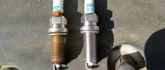
I obviously identified the faulty coil by the spark plugs - the spark plug in the first cylinder was different from the others - it was simply flooded. Full size A spark plug with a dark electrode was in the first cylinder, where the coil was faulty. A visual inspection confirmed the diagnostic result for the spark plugs.
I decided to measure the resistance of all contacts one by one in order to find the differences between the “healthy” coils and the faulty one. And the result was a technique for diagnosing coils using a multimeter.
Diagnostics is carried out in 2 stages: Visual inspection. A visual inspection of the rubber tips and the coil housing showed that the problem did not start yesterday. There were longitudinal cracks on the body along the axis of the reel.
Checking the ignition system (1ZZ-FE/ 3ZZ-FE)
Tightening torque: Install the spark plugs into the ignition coils and Toyota Vitz ignition coil diagnostics coil connectors. Connect the spark plugs to ground. Sparking of the spark plug Make sure that when cranking the crankshaft, sparks are formed on each spark plug (Fig. If an electrical shock is felt when touching a live spark plug, the ignition coil should be replaced.
Do not crank the engine crankshaft for more than 2.
If a spark does not form, perform the following checks. Checking the spark plug Fig. Spark plug cleaner Clean the spark plug fig.
If there are traces of carbon on the electrode, remove it with spark plug cleaner and dry it with compressed air. Air pressure: If there is no spark, replace the ignition coils.
If there is a spark, but the engine does not start, replace the spark plugs with new ones. If after this the engine does not start, check the serviceability of the engine management system.
How to check the ignition coil on a Vitz?
The most common cause of coil failure is overheating or turn-to-turn short-circuits caused by running the engine with excessively large spark plug spark gaps or gaps in high-voltage wire connections. The coils can be checked without removing them from the car.
You will need: The presence of a spark between the electrodes of the Toyota Vitz spark plug; diagnostics of the ignition coil for the serviceability of the coil. In addition, the coils can be checked with a spark-glow diagnostic device 1AP. To do this, disconnect the high voltage wires from the coil and connect the diagnostic device instead. Then turn the engine crankshaft with the starter; a spark should appear in the spark gap of the diagnostic tool in time with the operation of the cylinders.
For express check of the ignition coil for errors P0300, P030X.
- turn off the fuel pump by turning off its fuse - start the engine. - After the engine stalls, crank it two or three times to relieve fuel pressure. — remove all connectors from the ignition coils to avoid electrical discharge from the ignition coils. - turn on the ignition and crank the engine crankshaft with the starter for 5 or more seconds to remove combustion gases in the cylinder. - Connect the spark plug and the wiring harness connector to the ignition coil. - secure with a rope, etc. with a gap of 13 - 17 mm between the central electrode of the spark plug and the grounded metal as shown in the figure. - use the starter to crank the crankshaft for about 3 seconds, and check if there is a spark between the central electrode of the spark plug and the metal
CAUTION: • Do not get within 50cm of the spark plug and ignition coil. Be careful not to receive an electric shock during testing, as the electric discharge voltage is 20KV or more. • If the distance between the central electrode and the metal is more than 17mm, the ignition coil can be damaged. NOTE: If the gap is less than 13 mm when tested, a spark may be created even if the coil is faulty
Taken from the original Nissan manual
Video of checking the coils on the arrester, the third coil is faulty.
- why is the check light on?
- Why does the engine shake after washing?
- looking for battery current leak
- checking the generator without removing it
This test method is very visual, but it is not always possible to check ignition coils with a spark gap. In many modern cars, the ignition coils are located under the intake manifold. In this case, we use a motor tester to diagnose the ignition coils. Here is an example of diagnosing a faulty ignition coil of a Lexus RX300; the owner complained about a “triggering” engine and a flashing check. Also, driving with such a malfunction can lead to destruction of the catalyst.
This is what the oscillogram of a working ignition coil looks like:
- honda crv stalls
- honda accord troit
- toyota camry troit
- toyota corona troit
- why is the car shaking
The main reason for failure of ignition coils is worn-out spark plug electrodes; compare the spark gap of the left and right spark plugs.
Diagnostics of ignition coils with a multimeter — Toyota Corolla, l., year on DRIVE2
I obviously identified the faulty coil by the spark plugs - the spark plug in the first cylinder was different from the others - it was simply flooded. Full size A spark plug with a dark electrode was in the first cylinder, where the coil was faulty. A visual inspection confirmed the diagnostic result for the spark plugs.
I decided to measure the resistance of all contacts one by one in order to find the differences between the “healthy” coils and the faulty one. And the result was a technique for diagnosing coils using a multimeter.
Diagnostics is carried out in 2 stages: Visual inspection. A visual inspection of the rubber tips and the coil housing showed that the problem did not start yesterday. There were longitudinal cracks on the body along the axis of the reel.
Checking the ignition system (1ZZ-FE/ 3ZZ-FE)
Tightening torque: Install the spark plugs into the ignition coils and Toyota Vitz ignition coil diagnostics coil connectors. Connect the spark plugs to ground. Sparking of the spark plug Make sure that when cranking the crankshaft, sparks are formed on each spark plug (Fig. If an electrical shock is felt when touching a live spark plug, the ignition coil should be replaced.
Do not crank the engine crankshaft for more than 2.
If a spark does not form, perform the following checks. Checking the spark plug Fig. Spark plug cleaner Clean the spark plug fig.
If there are traces of carbon on the electrode, remove it with spark plug cleaner and dry it with compressed air. Air pressure: If there is no spark, replace the ignition coils.
If there is a spark, but the engine does not start, replace the spark plugs with new ones. If after this the engine does not start, check the serviceability of the engine management system.
How to check the ignition coil on a Vitz?
The most common cause of coil failure is overheating or turn-to-turn short-circuits caused by running the engine with excessively large spark plug spark gaps or gaps in high-voltage wire connections. The coils can be checked without removing them from the car.
You will need: The presence of a spark between the electrodes of the Toyota Vitz spark plug; diagnostics of the ignition coil for the serviceability of the coil. In addition, the coils can be checked with a spark-glow diagnostic device 1AP. To do this, disconnect the high voltage wires from the coil and connect the diagnostic device instead. Then turn the engine crankshaft with the starter; a spark should appear in the spark gap of the diagnostic tool in time with the operation of the cylinders.
Toyota Corolla ignition coils
The coil performs the main function in the ignition system, which ensures sparking of the spark plugs and stable operation of the engine. Therefore, in case of the slightest malfunction, you need to urgently fix the problem.
The correct operation of the ignition system in a car is very important. The original Corolla E120 ignition coil acts as a voltage transformer. If any element of the system fails, a complete diagnosis of all components is necessary. The procedure is simple, you can do it yourself.
Why is this element needed?
The ignition system coil is designed to produce high voltage voltage. It is generated from low voltage, which comes from the battery, and is transmitted to the spark plugs.
The operating diagram of this device is actually very simple, since there are only 5 parts in the ignition circuit: battery, coil, distributor, breaker, capacitor, spark plugs. Each of them plays a specific role and is closely connected to the ignition coil.
Damage to this part has an extremely negative effect on the ignition system and the engine as a whole. Any breakdown can prevent the operation of the entire power unit. If there is current in the coil and the cylinder rises to top dead center, the breaker (one of the constituent elements of the ignition system) is triggered, which breaks the circuit of the primary winding. If there is a malfunction, instead of further transmitting the pulse to the distributor, a short circuit will occur, which will disable the entire ignition system. As a result, the car will stall and will not start again.
Toyota Corolla ignition system
The Corolla is equipped with two types of ignition systems: with an external and internal electronic unit.
Toyota Corolla ignition system. Photo source: https://fielder-toyota.ru/electrician3.html
They differ in the location of the switch.
How does the Toyota Corolla ignition system work?
The design of the ignition system of the Japanese car Toyota Corolla E100 from 1996 to 1997:
- egnition lock;
- accumulator battery;
- sensor-distributor;
- transformer;
- crankshaft position sensor;
- ignition module;
- engine control module;
- chain of low-voltage wires;
- high voltage wires;
- candles.
Differences in ignition systems between different Toyota models
From 1998 to 2000, Toyota installed a distributorless ignition, which consists of a camshaft sensor, a crankshaft sensor, two coils for 4 cylinders and an ECM module.
Toyota Corolla ignition system repair
Before starting to repair this unit, you first need to make sure that this particular part has failed.
Is it possible to repair the ignition coil?
The most common cause of failure is a high voltage breakdown. You can repair the Toyota Corolla coil yourself.
Toyota Corolla ignition system repair. Photo source: https://web-site1.ru
Step-by-step instructions for performing the work:
- in a radio parts store, pick up a heat-shrinkable tube with a diameter of 23-25 mm;
- degrease the part with a special agent;
- prepare 2 tubes of the same length;
- install 1 tube on the coil body;
- To ensure reliable shrinkage, heat the part;
- with tube 2, repeat the same steps to create a second layer.
Some car enthusiasts fix the problem using epoxy resin according to the following scheme:
- the part must be completely dried;
- prepare a container with well-heated epoxy resin;
- use electrical tape to hermetically hide the group of contacts;
- lower the coil into the container up to the silicone tip;
- Allow to dry and you can install.
How to change the ignition coil yourself
Corolla E-150 vehicles use coils with replaceable tips; if misfires are detected, the condition of the elements should be checked. The car owner needs to check the condition of the windings with a test device, and then install new tips made of special rubber. To hold the nozzle on the reel body, a protrusion is provided; in addition, high-temperature silicone sealant is applied to the surface.
What you will need
To perform repair work on Toyota Corolla E-150 sedans you will need:
- set of wrenches;
- rags for wiping;
- a flat blade screwdriver for removing the tip.
Step-by-step instruction
To install new parts on a 2008 Corolla E-150, you must:
- Drive the car into a garage or onto a level area and turn off the engine.
- Raise the parking brake and then open the hood.
- Remove the decorative plastic cover from the engine.
- Disconnect the electrical wiring plug by carefully releasing the clamp. Do not pull the terminal block by the wires due to the risk of damaging the wires or insulation.
- Using a 10 mm socket, unscrew the mounting bolt and then pull the coil out of the well. Inspect the tip and check the condition by squeezing the rubber with your fingers; cracks will be visible on the worn part. If there are traces of corrosion on the metal surface, then it is necessary to clean the metal from rust with fine sandpaper (the procedure is carried out if the product continues to be used).
- Install a new tip or unpack the coil assembly and check the condition of the part.
- If necessary, change the spark plug, and then carefully insert the new coil until it stops.
- Tighten the mounting bolt and connect the wiring plug until the latch clicks.
- Replace the decorative engine cover, close the hood and perform a test run. When the power unit is operating, there should be no vibrations or drops in speed, accompanied by flashing or constant lighting of the Check Engine indicator.
On older Corolla models (for example, with the E-100 body), a common coil is used that works in conjunction with a mechanical ignition pulse distributor. To replace, you will need to disconnect the high-voltage wires, unscrew the fasteners and carefully remove the distributor cover and slider. Then you will need to dismantle the failed part and reassemble the distributor. When connecting the wires, it is important not to make a mistake with the cylinder numbers, otherwise the engine will not start or will operate unstable.
On some machines, access to the distributor is limited by pipes and the air filter housing. A similar problem occurs on the Corolla E-110 with the 5A-FE engine. To simplify access, remove the cover of the filter box with the pressure hose. When removing the slider, do not use a metal tool that can damage the edges of the part. The coil is secured with 4 Phillips head screws.
What to choose: original or analogue
You can install not only original Japanese coils on a Toyota Corolla, but also analogues.
Toyota ignition coil 90919-02258. Photo source: https://claz.org/classifieds?q=ignition+coil
- The replacement part should be selected by VIN code, year of manufacture, body type. It is better to ask the seller for help.
- It is necessary to take into account the compatibility of the transformer with the volume of the power unit, since a large engine volume requires more voltage.
The choice of transformers is huge; you can choose a high-quality part for a reasonable price. Photos of the original elements and their analogues are available on the Internet.
Cost of ignition coil for Toyota Corolla
On sale you can find original reels from well-known manufacturers, including used ones, which serve for a long time. These include:
- Toyota 90919-02258 – cost: 6650 rubles;
- Toyota Denso Dic 01-01 – price: 4400 rubles.
You can choose analogues that will also last a long time, but the manufacturer does not guarantee quality.
- Delphi gn10341- 12B 1 – price: 1860 rubles;
- Masuma MIC112 – cost: 2000 rubles;
- NGK 48 395 – price: 1900 rubles;
- NGK U5145 – cost: 2150 rubles.
Among the Chinese analogues, Sailing tyl 91902258 is popular - cost: 1180 rubles.
Reviews from car owners
Roman, 43 years old, St. Petersburg:
“When replacing spark plugs, I discovered cracks on the ignition coils and tips. Factory coils, covered 200,000 km. Friends advised us to install NGK 48 395 transformers. After the replacement, 50,000 km passed, there were no problems. I recommend".
Evgeniy, 30 years old. Rostov:
“The other day I was driving home from work, the engine revved up and the Check light came on: error P0351 (ignition coil). I did some diagnostics and it turned out that the coil had burned out. I went to the store and bought a Masuma MIC-112 transformer. After installing the part, I drove 23,000 km. As long as it works, I recommend it."
The coil performs the main function in the ignition system, which ensures sparking of the spark plugs and stable operation of the engine. Therefore, in case of the slightest malfunction, you need to urgently fix the problem, otherwise a breakdown will occur, which will lead to expensive repairs.
Plugs and ignition coil Toyota Corolla 120
The reliability of ignition of the air-fuel mixture and the stability of the Toyota Corolla 120 power plant depend on the condition of the spark plugs and ignition coils. Failure of any of the elements leads to engine tripping, a significant deterioration in dynamics, an increase in fuel consumption and can cause a reduction in engine life. Therefore, it is extremely important to change spark plugs and ignition coils in a timely manner, purchasing only recommended products.
Signs of a broken ignition coil
Main symptoms of a malfunction:
- difficulty starting the engine (the problem may be intermittent and depend on temperature or air humidity);
- floating idle speed until the engine stops spontaneously;
- jerking and unstable operation of the power unit under load;
- increased fuel consumption (subject to maintaining the management style and operating conditions).
On Corolla cars with an electronic fuel injection system, diagnostics of components is provided with recording of error codes P0351...P0354. If the spark plugs are unstable, information about the malfunction is entered into the controller’s memory, and an orange “check” light turns on in the instrument cluster. You can read codes using a scanner or adapter connected to the OBD II diagnostic connector. If the errors are random, then after the information is deleted the indicator goes out. When the problem is fixed again, the code is written again.
Article and price of branded candles for Corolla 120 and their analogues
The original spark plugs that come with the Corolla 120 are Toyota SK20R11. Their article number is 9008091180.
The price of branded candles ranges from 400 to 600 rubles. The car can also be equipped with Denso Iridium Tough VK20 iridium spark plugs, the cost of which reaches 800 rubles.
Moreover, their service life is up to 100 thousand km. Other analogues of the original Toyota Corolla 120 spark plugs can be found in the table below.
Table - Good analogs of original spark plugs for Corolla 120
| Brand | Catalog number | Cost, ruble |
| NGK | IFR6T11 | 420-450 |
| Beru | Z280 | 380-410 |
| Febi | 13609 | 340-400 |
Recommendations for replacement intervals
According to the automaker's recommendation, spark plugs should be replaced every 50 thousand km. Original products can last longer, so car owners are advised to replace them after reaching a mileage of 70 thousand km.
During the operation of the vehicle, unscheduled replacement of spark plugs may be required. It is usually associated with their damage or lack of a normal spark between the electrodes. Situations when it is necessary to install a new set of spark plugs are shown in the image below.
Cost of replacing the coil in the service
If the owner of a Corolla car does not have the skills to repair equipment, then you can contact a service center. The cost of diagnosing and replacing ignition system components depends on the region. The price of the service varies from 300 rubles. In small towns and regional centers up to 1,500 rubles. in Moscow or St. Petersburg. The owner is offered additional services such as replacing spark plugs or carrying out comprehensive vehicle maintenance.
Source
Tools required to replace spark plugs
In order for the spark plug replacement to be successful, you will need the tools from the table below.
Table - Tools for replacing spark plugs on Corolla 120
| List of tools | Notes |
| Candle key | "at 16" |
| Key | "on 10" |
| Torque wrench | To control the tightening torque |
| Dielectric gel | To reduce the risk of electrical breakdown |
Description of replacing spark plugs on Toyota Corolla 120
It is recommended to replace spark plugs on a Corolla 120 according to the instructions given below.
- Open the hood.
- Disconnect the negative terminal from the battery.
- Unscrew the two nuts securing the decorative engine cover and remove it.
- Clean up dirt.
- Remove the terminal block from the ignition coil. To do this, you need to hold the latch on it and pull the connector.
- Using a wrench, unscrew the ignition coil.
- Pull the spool up with force. This will allow you to remove it from the spark plug well.
- Blow out contamination from the spark plug well. This will prevent debris from getting into the working chamber or onto the threads.
- Unscrew the spark plug.
- Using a spark plug wrench, remove the spark plug from the well.
- Screw in a new spark plug. It is recommended to control the tightening torque, which should be 25 Nm.
- Treat the ignition coils with dielectric gel.
- Reassemble everything in the reverse order of removal.
Toyota Corolla engine management system, replacement of coils, spark plugs, sensors
The engines installed on Toyota Corolla cars are equipped with an electronic engine management system with distributed fuel injection. This system ensures compliance with modern emission and evaporation standards while maintaining high driving performance and low fuel consumption. The control device in the system is the electronic control unit (ECU). Based on the information received from the sensors, the ECU calculates the parameters for regulating fuel injection and controlling the ignition timing. In addition, in accordance with the established algorithm, the ECU controls the operation of the electric motors of the engine cooling system fan and the electromagnetic clutch for turning on the air conditioning compressor, performs the function of self-diagnosis of system elements and notifies the driver of any malfunctions that have arisen. If individual sensors and actuators fail, the ECU turns on emergency modes to ensure engine operation. The amount of fuel supplied by the injectors is determined by the duration of the electrical signal from the ECU. The electronic unit monitors data on the engine condition, calculates the fuel requirement and determines the required duration of fuel supply by the injectors (signal duration). To increase the amount of fuel supplied, the signal duration increases, and to decrease the fuel supply, it decreases. The engine control system, along with the electronic control unit, includes sensors, actuators, connectors and fuses. Electronic control unit
(controller) is connected by electrical wires to all sensors of the system. Receiving information from them, the unit performs calculations in accordance with the parameters and control algorithm stored in the memory of the programmable read-only memory (PROM) and controls the system's actuators. The program version recorded in the PROM memory is indicated by the number assigned to this modification of the ECU. The control unit detects a malfunction, identifies and stores its code, even if the fault is unstable and disappears (for example, due to poor contact). The engine management system malfunction indicator in the instrument cluster goes out after three ignition on/off cycles after the failed unit has been restored to functionality. After repair, the fault code stored in the control unit's memory must be erased. To do this, turn off the power supply to the unit for 1 minute (remove the fuse for the power supply circuit of the electronic control unit or disconnect the wire from the negative terminal of the battery). The unit supplies 5 and 12 V direct current to various sensors and switches of the control system. Since the electrical resistance of the power circuits is high, the test lamp connected to the system terminals does not light up. To determine the supply voltage at the ECU terminals, use a voltmeter with an internal resistance of at least 10 MOhm. The ECU is not suitable for repair; if it fails, it must be replaced. The inductive type crankshaft position sensor is designed to synchronize the operation of the electronic control unit with the TDC of the pistons of the 1st and 4th cylinders and the angular position of the crankshaft. The sensor is installed at the front of the engine opposite the drive disc on the engine crankshaft. The drive disk is a toothed wheel with cavities. Two teeth are cut to create a synchronization pulse (“reference” pulse), which is necessary to coordinate the operation of the control unit with the TDC of the pistons in the 1st and 4th cylinders. As the crankshaft rotates, the teeth change the sensor's magnetic field, inducing pulses of alternating current voltage. The control unit uses sensor signals to determine the crankshaft rotation speed and send pulses to the injectors. If the sensor fails, starting the engine is impossible. Inductive type phase sensors are installed in the upper left part of the cylinder head. As the camshaft rotates, the protrusion of its drive disc changes the sensor's magnetic field, inducing alternating current voltage pulses. The sensor signals are used by the controller to organize phased fuel injection in accordance with the operating order of the cylinders, as well as to control the change in valve timing depending on the engine operating mode. If a malfunction occurs in the camshaft position sensor circuit, the controller stores its code in its memory and turns on the alarm. The coolant temperature sensor is installed in the engine cooling system. The sensitive element of the sensor is a thermistor, the electrical resistance of which varies inversely with temperature. At a low coolant temperature (-20 'C), the thermistor resistance is 15-30 kOhm; when the temperature rises to +80 'C, it decreases to 320 Ohm. The electronic unit supplies the temperature sensor circuit with a constant reference voltage. The sensor signal voltage is maximum when the engine is cold and decreases as it warms up. Based on the voltage value, the electronic unit determines the engine temperature and takes it into account when calculating injection and ignition adjustment parameters. If the sensor fails or there is a disturbance in its connection circuit, the ECU sets a fault code and stores it. In addition to what is described, the sensor indirectly serves as a coolant temperature indicator sensor in the instrument cluster. Based on the information from this sensor, the electronic engine control unit changes the indicator readings. To eliminate the malfunction, check the reliability of the contact connections in the wiring to the sensor or replace the sensor. The mass flow and incoming air temperature sensor is installed in the air hose between the air filter and the throttle assembly. The operating principle of the mass air flow sensor is based on maintaining a constant temperature of the resistors (the higher the air flow rate, the greater the current required to maintain the temperature of the resistor). The operating principle of the incoming air temperature sensor is similar to the operating principle of the coolant temperature sensor. Depending on the readings of these sensors, the ECU adjusts the amount of fuel injected into the cylinder to obtain the optimal working mixture. The throttle position sensor is made integral with the throttle cover. The operating principle of the sensor is based on the Hall effect. When the throttle valve is turned (by operating the control pedal), the voltage at the sensor output changes. When the throttle valve is closed, it is below 2.5 V. When the throttle valve opens, the voltage at the sensor output increases; when the throttle valve is fully open, it should be more than 4 V. By monitoring the sensor output voltage, the ECU adjusts the fuel supply depending on the throttle valve opening angle (t i.e. at the driver’s request). The throttle position sensor does not require adjustment, since the control unit perceives idle speed (i.e. fully closing the throttle valve) as the zero mark. Oxygen concentration sensors (lambda probes) are screwed into the threaded holes of the catalytic collector and the exhaust pipe of the exhaust gas system. The sensor at the inlet to the catcollector is used to control the composition of the air-fuel mixture, and the sensor on the receiving pipe is used to evaluate the efficiency of the converter. In the metal flasks of the sensors there is a galvanic element washed by the flow of processed gases. Depending on the oxygen content in the exhaust gases as a result of combustion of the air-fuel mixture, the voltage of the sensor signals changes. Information from each sensor enters the control unit in the form of low and high level signals. When there is a high level signal (about 4.2 V) from the sensor at the input to the cat-manifold, the control unit receives information about the high oxygen content. A low level signal (about 2.2 V) from this sensor indicates a low oxygen content in the exhaust gases. The characteristics of the sensor at the outlet of the catalytic collector are different: a high oxygen content corresponds to a low level signal (about 0.1 V), and a low oxygen content corresponds to a high level signal (about 0.9 V). By constantly monitoring the voltage of the sensor signal, the control unit adjusts the amount injected by the injectors fuel. When the signal level of the sensor at the inlet to the catalytic collector is high (poor air-fuel mixture), the amount of fuel supplied increases; when the signal level is low (rich mixture), it decreases. If the signal level of the sensor at the converter output does not correspond to the values permissible for this operating mode, the control unit identifies a fault in the catalytic converter. The knock sensor is attached to the top of the cylinder block between the 2nd and 3rd cylinders and detects abnormal vibrations (knock knocks) in the engine. The sensitive element of the knock sensor is a piezocrystal plate. During detonation, voltage pulses are generated at the sensor output, which increase with increasing intensity of detonation impacts. The controller, based on the sensor signal, adjusts the ignition timing to eliminate fuel detonation flashes. During operation, the electronic engine control unit also uses vehicle speed data received from the ABS control unit. Hydraulic phase change valves are installed on the upper right part of the cylinder head cover. The valves regulate the oil pressure supplied to the timing actuators mounted at the front ends of the camshafts. The system optimally adjusts the valve timing, changing them over the entire range of engine frequencies and loads, increasing power and torque at any speed mode. When the engine stops, oil pressure forces the control valve spool to move to the position corresponding to the latest valve timing. The control valve is activated by the engine control signal and supplies oil either to the retardation chamber or to the advance chamber with a continuous change in the valve timing either towards their advance or towards the retardation. Before removing any components of the fuel injection control system, disconnect the cable from the negative terminal of the battery. Do not start the engine if the battery cable terminals are not properly tightened. Never disconnect the battery from the vehicle's on-board power supply while the engine is running. When charging the battery, disconnect it from the vehicle's on-board power supply. Do not expose the ECU to temperatures above 65 °C when in operation and above 80 °C when not in operation (for example, in a drying chamber). It is necessary to remove the ECU from the car if this temperature is exceeded. Do not disconnect or connect wires from the computer when the ignition is on. Before performing electrical welding work on a vehicle, disconnect the wires from the battery and the wiring harness connectors from the ECU. Perform all voltage measurements with a digital voltmeter with an internal resistance of at least 10 MOhm. The electronic components used in the fuel injection system are designed for very low voltage, so they can easily be damaged by electrostatic discharge. To prevent damage to the computer, do not touch its terminals with your hands. To diagnose the engine management system in all cases, a special scanner is required, so if system malfunctions occur, contact a specialized service.
Replacing Toyota Corolla coils
1. Remove the decorative engine cover 2. Disconnect the wire from the negative terminal of the battery. 3. Squeezing the clamps, disconnect the wiring harness block from the ignition coil being removed. 4. Unscrew the bolt securing the ignition coil to the cylinder head cover 5. ... and remove the ignition coil from the cylinder head well. 6. Install the parts in the reverse order of removal.
Replacing spark plugs for Toyota Corolla
You will need a special 16mm wrench to remove the spark plugs (with a rubber bushing to hold the spark plugs).
On the 4ZZ-FE engine of a Toyota Corolla, DENSO K16R-U11 spark plugs with a gap between the spark plug electrodes of 1.0-1.1 mm or BOSCH FR8KCU with a gap between the spark plug electrodes of 0.9-1.0 mm are installed. On 1ZR-FE and 1NR-FE engines, DENSO SC20HR11 spark plugs are used with a gap between the spark plug electrodes of 1.0-1.1 mm. 1. Disconnect the wire from the negative terminal of the battery 2 Remove the ignition coil 3. Blow out the spark plug well with compressed air to prevent dirt from getting into the engine cylinder when removing the spark plug 4 Unscrew the spark plug.. 5. ... and remove it from the spark plug well. 6. Unscrew the remaining spark plugs in the same way. 7. Using a round feeler gauge, check the gap between the spark plug electrodes. 8. If the gap differs from the specified value, adjust it by bending the side electrode. 9 Remove and check the remaining spark plugs in the same way. 10. Install the parts in the reverse order of removal.
REMOVAL AND INSTALLATION OF THE ELECTRONIC ENGINE CONTROL UNIT 1. Disconnect the wire from the negative terminal of the battery. 2. Remove the air filter 3. Press the tab of the lock...
4. ...and fold the lock up. 5. Disconnect the left connector from the electronic engine control unit. 6. Similarly, disconnect the right connector of the electronic engine control unit. 7. Remove four screws. 8. ...and remove the computer. 9. Install the parts in the reverse order of removal.
CHECKING AND REPLACING ENGINE CONTROL SYSTEM SENSORS Crankshaft position sensor Toyota Corolla
installed in the front of the engine cylinder block.
If a malfunction occurs in the crankshaft position sensor circuit, the engine stops working, the controller stores a fault code in its memory and turns on the warning light in the instrument cluster. In this case, check the sensor and drive disc for missing teeth, runout, or other damage. You will need: all the tools necessary to remove the engine mudguards, as well as a 10mm wrench and a tester. 1. Disconnect the wire from the negative terminal of the battery. 2. Remove the right lower and side engine mudguards. 3. Disconnect the crankshaft position sensor wiring harness connector. 4. Remove the mounting bolt.. 5. ...and remove the crankshaft position sensor. 6. To check the serviceability of the crankshaft position sensor, measure the resistance between the contacts of its block. At temperatures from +10 to +50 °C, the resistance should be 985-1600 Ohms. 7. Install the engine crankshaft position sensor in the reverse order of removal. Toyota Corolla phase sensors
are installed in the upper left part of the cylinder head.
If there is a malfunction in the sensor circuit, the controller stores a fault code in memory and uses a bypass engine control program (without changing the valve timing). You will need a key "10". Replacement of the phase sensor on the intake shaft of the gas distribution mechanism is shown. The phase sensor on the exhaust shaft is replaced in the same way. 1. Remove the decorative engine cover 2. Disconnect the wire from the negative terminal of the battery. 3. Disconnect the wiring harness block from the phase sensor... 4. ... unscrew the fastening bolt.. 5. ... and remove the sensor from the hole in the cylinder head. 6. To check the serviceability of the sensor, measure the resistance between its contacts. At temperatures from +10 to +50 °C, the resistance should be 835-1400 Ohms. 7. Install the phase sensor in the reverse order of removal. The Toyota Corolla coolant temperature sensor
is screwed into a threaded hole in the cylinder head. In the event of a sensor failure, the controller stores a fault code and uses a bypass engine control program (calculates the approximate value of the coolant temperature based on engine operating time and air mass flow). You will need: a 19" wrench, a tester, a thermometer. 1. Remove the decorative engine cover 2. Disconnect the wire from the negative terminal of the battery. 3. Drain the engine cooling system
Data for checking the Toyota Corolla temperature sensor
When replacing the sensor, the coolant does not need to be drained: after removing the sensor, plug the hole with your finger or a plug - the loss of coolant will be minimal. 4. Disconnect the wiring harness connector from the coolant temperature sensor by squeezing the retainer. 5. Unscrew the sensor from the hole in the cylinder head. 6. Immerse the sensor in hot water and use a tester to check the change in resistance between the sensor terminals as the water cools, monitoring the water temperature with a thermometer. The resistance values of a working sensor are given in Table 7. If the resistance deviates from the norm, replace the sensor. 8. Screw in the coolant temperature sensor and tighten it to a torque of 20 Nm. Install the remaining parts in the reverse order of removal. 9. Fill with coolant. A combined mass flow
and incoming air temperature sensor is installed in the air hose between the air filter and the throttle body.
If the sensor malfunctions, the controller stores a fault code and uses a bypass engine control program (calculates the approximate mass air flow based on the crankshaft speed and throttle position). Checking the mass flow sensor and incoming air temperature must be performed at a service station using a scanner connected to the diagnostic connector. 1. Disconnect the wire from the negative terminal of the battery. 2. Squeeze the clamp... 3. ...and disconnect the wiring harness block from the sensor. 4. Unscrew the two mounting screws and remove the mass flow and incoming air temperature sensor. 5. Inspect the platinum element of the mass air flow sensor (shown with an arrow in the photo) and make sure that it is not broken or has foreign particles on it. If a break in the platinum element is detected, replace the sensor. 6. Using a tester, check the change in resistance between terminals A and B of the sensor as the temperature changes. The resistance values of a working sensor are given in Table 7. If the resistance deviates from the norm, replace the sensor. 8. Install the combined sensor in the reverse order of removal. Toyota Corolla throttle position sensor
.
whose action is based on the Hall effect, is connected to the throttle axis. Rotation of the damper axis causes a change in the voltage of the sensor signal, by which the controller determines the degree of opening of the throttle valve. The sensor is built into the throttle body cover, so if the sensor fails, replace the throttle body assembly. Toyota Corolla oxygen concentration sensors
are installed on the exhaust manifold and the exhaust pipe.
The sensor on the exhaust manifold is control... ...the sensor on the exhaust pipe is diagnostic. Both sensors have a similar design, but differ in characteristics. If at least one of the oxygen concentration sensors is faulty, the toxicity of exhaust gases can increase sharply and fuel consumption will increase. You will need: a 22 key, a tester. To replace the oxygen concentration control sensor, perform the following steps. 1. Disconnect the wire from the negative terminal of the battery. 2. Remove the decorative engine cover. 3. Squeeze the clamps and disconnect the sensor wiring harness block.. 4. ...then unscrew the control sensor from the hole in the catenary collector. 5. To check the serviceability of the control oxygen concentration sensor, measure the resistance between contacts “1” and “2” of its block. At a temperature of +20 “C, the resistance should be 1.8-3.4 Ohms. 6. Install the control oxygen concentration sensor in the reverse order of removal. To replace the diagnostic oxygen concentration sensor, perform the following steps. 1. Disconnect the wire from the negative terminal of the battery. 2. Remove the wiring harness holder from the body base. 3. Squeeze the clamps and disconnect the wiring harness block of the diagnostic oxygen concentration sensor... 4. ...then unscrew the sensor from the exhaust pipe hole. 5. To check the serviceability of the diagnostic oxygen concentration sensor, measure the resistance between contacts “1” and “2” of its block. At a temperature of +20 'C, the resistance should be 11-16 Ohms. 6. Install the diagnostic oxygen concentration sensor in the reverse order of removal. The Toyota Corolla knock sensor
is installed on a bolt screwed into the wall of the cylinder block in its upper part.
If the sensor fails, the controller stores a fault code in memory and uses a bypass engine control program (with a reduced ignition timing to eliminate detonation). You will need: all the tools to remove the engine intake pipe. 1. Remove the decorative engine cover 2. Disconnect the wire from the negative terminal of the battery 3. Remove the engine inlet pipe 4. Squeeze the clamp... 5. ...and disconnect the wiring harness block from the knock sensor. 6. Unscrew the bolt and remove the knock sensor from the stud. 7. To check the serviceability of the knock sensor, measure the resistance between its contacts. At a temperature of +20 “C, the resistance should be 120-180 kOhm. 8. Install the knock sensor in the reverse order of removal. Toyota Corolla hydraulic phase change valves
are installed on the upper right part of the cylinder head cover. The valves regulate the oil pressure supplied to the timing actuators mounted at the front ends of the camshafts. You will need a key "10". Shown is replacing the hydraulic timing valve on the intake camshaft. The hydraulic phase change valve on the exhaust camshaft is replaced in the same way. 1. Disconnect the wire from the negative terminal of the battery 2. Remove the decorative engine cover 3. Press the latch. 4. ...and disconnect the engine management system wiring harness connector from the hydraulic phase change valve. 5. Remove the bolt securing the hydraulic phase change valve.. 6. ...and remove the valve from the cylinder head. Please note the hydraulic timing valve markings to ensure that you purchase a similar new valve. When removing the hydraulic timing valve, be sure to replace the O-rings.
7. To check the serviceability of the knock sensor, measure the resistance between its contacts. At a temperature of +20 °C, the resistance should be 6.9-7.9 Ohms. 8. Install the hydraulic phase change valve 8 in the reverse order of removal.
Tags system, Toyota Corolla, engine management, spark plugs, sensors, replacing coils
Article number and cost of the original ignition coil for Corolla 120 and its analogues
The original Corolla 120 ignition coil has catalog number 9091902262. Its cost is about 3,000 rubles. Since the price for a branded product is quite high, many car owners purchase reels from car dismantling yards.
The cost for a used spare part is in the range of 700-1000 rubles. An alternative solution to the problem of a failed ignition coil is to purchase an analogue of a branded product from third-party manufacturers. The best brands, according to reviews from car owners, are listed in the table below.
Table - Ignition coils for Corolla 120 from third-party manufacturers
| Company manufacturer | Article number | Cost, ruble |
| Febest | TCP001 | 400-450 |
| Masuma | MIC103 | 1600-1800 |
| Magneti Marelli | BAEQ126 | 1000-1200 |
| YEC | IGC104F | 1200-1300 |
| Mobiletron | CT25 | 1400-1500 |
| Tesla | CL555 | 1000-1100 |
| Japan Cars | K72005 | 1100-1250 |
| EPS | 1970461 | 1600-1900 |
| Delphi | GN1031412B1 | 2100-2300 |
Description of the process of checking the ignition coil on the Corolla 120
If you suspect that one of the ignition coils has failed, you must use the method below to identify the faulty element:
- Start the power plant.
- Open the hood.
- Remove the ignition coils one by one. If the sound of the motor does not change after removing the coil, then with a high degree of probability this indicates its malfunction. This method carries the risk of damaging the ECU, so it should only be used in extreme cases.
Another method of identifying a faulty coil is to install a known-good product in its place. The main disadvantage of this method is the need to have a spare, working coil.
- An indirect sign of a coil malfunction is the unsatisfactory condition of one of the spark plugs. Due to the lack of normal ignition, carbon deposits appear on the electrodes.
Checking the ignition coil should begin with its visual inspection. It is necessary to check the condition of the body and tips. There should be no cracks, deformations, soot or discoloration.
If there are defects, do not try to eliminate them using electrical tape or heat shrink. Their breakdown voltage is much lower than that created by the ignition coil. The only way to repair is to replace the damaged area with epoxy resin.
If a visual inspection does not reveal any defects, then it is necessary to check the condition of the coil using measuring instruments. They can be used as a multimeter or ohmmeter. It is necessary to measure the resistance at the control points. They are the central electrode and the terminal block contacts.
To check if the coil is faulty, you need to check the resistance between the contacts and the central electrode. The data obtained should be entered into the table and compared with a working coil. Any significant deviations indicate a malfunction of the product being tested.
Table - Summary data to identify a faulty coil
It is also necessary to check the condition of the insulation. To do this, use a megger or multimeter. You should check that there is no breakdown between the contacts and the housing.
How to check and replace the ignition coil
Checking the coil on 1.6-liter 4-cylinder Toyota gasoline engines is carried out in the same way. Naturally, first you need to find the part. Let's consider this procedure using the example of a 2008 1.6 MT Corolla 150. You can find the part near the engine, since it is located at the end of the distributor wire approximately between the power plant and the passenger compartment. However, for initial diagnostics, you must first remove the tip from one spark plug, move it to another, pull the body of this small part to ground, and only then start the car for a short period of time.
Proper operation will be indicated by a spark that appears between the electrodes of the spark plugs. In this case, replacement is not necessary. An additional check is carried out with a special device that is connected to the coil instead of a high voltage wire. It is not necessary to start the engine for diagnostics: it is enough to manually crank the crankshaft to find out whether there is a spark or not.
A complete check is carried out using an ohmmeter. To do this, you need to disconnect the blocks and wires with high voltage, connect the device to the contacts of the primary and then the secondary winding and measure the resistance, the value of which is 0.4–0.5 Ohm and 5–7 kOhm, respectively.
On any Toyota Corolla car with a 1.6-liter engine, be it the E12, 150 or even 170, changing the coil is the same. By the way, this is done very easily and quickly. If the malfunction does not escape the part, you need to unscrew the two bolts that secure it to the cylinder head cover with a 10mm wrench. Then you need to disconnect the bolts with the clamping bar, after which the cherished action will become available.
You can install both the original and other samples. Regarding the latter, there are several recommendations. First, you need to take parts that are compatible with 1.6-liter engines. The fact is that engines with larger cylinders require higher voltage, so such coils are not suitable for standard 150 body configurations. Secondly, it is better to take a more expensive model with one or two elastic bands separating the turns. This will eliminate as much as possible the possibility of voltage loss, as well as accidental short circuiting.