All errors TOYOTA 4RUNNER, ALLEX, ALLION, ALPHARD, ALTEZZA, ARISTO, AURION, AURIS, AVALON, AVENSIS, AYGO, BB, BELTA, BLADE, BREVIS, CALDINA, CAMI, CAMRY, CELICA, CELSIOR, CENTURY, COROLLA, ECHO, ESTIMA , FJ CRUISER, FORTUNER, FUNCARGO, GT86, HARRIER, HIACE, HIGHLANDER, HILUX, INNOVA, IPSUM, iQ, ISIS, IST, KLUGER HYBRID, KLUGER V, LAND CRUISER, LAND CRUISER PRADO, MARK, MARK X, MATRIX, MR 2 , NADIA, NOAH, OPA, PASSO, PLATZ, PREMIO, PREVIA, PRIUS, PROBOX, PROGRES, RACTIS, RAUM, RAV4, RUSH, SAI, SEQUOIA, SIENNA, SIENTA, SOLARA, TACOMA, TUNDRA, URBAN CRUISER, VANGUARD, VELLFIRE, VENZA, VERSO, VITZ, VOLTZ, VOXY, WILL CYPHA, WILL VS, WINDOM, WISH, YARIS.
TEST SEQUENCE
Turn on the ignition (IG).
Check the operation of the passenger front airbag off warning lamp
HINT: Refer to the normal operation of the passenger front airbag warning light (Click here).
Result:
| On/off indicator light illumination | Next step |
| Lamp stays on continuously | A |
| OFF | B |
Disconnect the cable from the negative (-) battery terminal and wait at least 90 seconds.
Check that the connector is properly connected to the air conditioning control panel (*1) or to the warning lamp (*2).
OK: The connector is connected correctly.
HINT: If the connector is not securely connected, reconnect it and proceed to the next test.
Disconnect the connector from the air conditioning control panel (*1) or from the warning light (*2).
Make sure the connector pins are not damaged.
OK: The contacts are not deformed or damaged.
- *1: For models with automatic air conditioning and hatchback body type
- *2: For manual air conditioning hatchback and sedan models
Disconnect the cable from the negative (-) battery terminal and wait at least 90 seconds.
Check that the connectors are correctly connected to the SRS central control unit assembly.
OK: The connector is connected correctly.
HINT: If the connector is not securely connected, reconnect it and proceed to the next test.
Disconnect the connectors from the SRS central control unit.
Make sure the connector pins are not damaged.
OK: The contacts are not deformed or damaged.
Disconnect the cable from the negative (-) battery terminal and wait at least 90 seconds.
Connect the connector to the SRS central control unit assembly.
Connect the cable to the negative (-) terminal of the battery and wait at least 2 seconds.
Turn the ignition ON (IG) and wait at least 60 seconds.
Clear stored DTCs (Click here).
Turn the ignition ON (IG) and wait at least 60 seconds.
OK: DTC B1660/43 is not output.
HINT: Codes other than B1660/43 may be displayed at this time and are not associated with this test.
Result:
| Result | Next step |
| OK | A |
| NG (for sedan models) | B |
| NG (for hatchback models) | C |
Disconnect the cable from the negative (-) battery terminal and wait at least 90 seconds.
Check that the connector is properly connected to the air conditioning control panel (*1) or to the warning lamp (*2).
OK: The connector is connected correctly.
HINT: If the connector is not securely connected, reconnect it and proceed to the next test.
Disconnect the connector from the air conditioning control panel (*1) or from the warning light (*2).
Make sure the connector pins are not damaged.
OK: The contacts are not deformed or damaged.
- *1: For models with automatic air conditioning and hatchback body type
- *2: For manual air conditioning hatchback and sedan models
Using a process wire, connect pins 23 (PAON) and 17 (P-AB) of connector B.
NOTE: When connecting, do not force the process wire into the connector contact.
Measure the resistance according to the values given in the table below.
Rated Resistance: For models with automatic air conditioning and hatchback body style:
| Contacts for connecting a diagnostic tool | Switch position | Specified conditions |
| E76-3 (PAON) - E76-4 (P-AB) | Always | Less than 1 ohm |
For manual air conditioning hatchback and sedan models:
| Contacts for connecting a diagnostic tool | Switch position | Specified conditions |
| E48-7 (PAON) - E48-6 (P-AB) | Always | Less than 1 ohm |
Measure the resistance according to the values given in the table below.
Rated Resistance: For models with automatic air conditioning and hatchback body style:
| Contacts for connecting a diagnostic tool | Switch position | Specified conditions |
| E76-3 (PAON) - weight | Always | 1 MΩ or more |
| E76-4 (P-AB) - weight | Always | 1 MΩ or more |
For manual air conditioning hatchback and sedan models:
| Contacts for connecting a diagnostic tool | Switch position | Specified conditions |
| E48-7 (PAON) - weight | Always | 1 MΩ or more |
| E48-6 (P-AB) - weight | Always | 1 MΩ or more |
Connect the cable to the negative (-) terminal of the battery and wait at least 2 seconds.
Turn on the ignition (IG).
Measure the voltage according to the values given in the table.
Rated Voltage: For models with automatic air conditioning and hatchback body style:
| Contacts for connecting a diagnostic tool | Switch position | Specified conditions |
| E76-3 (PAON) - weight | Ignition on (IG) | Less than 1 V |
| E76-4 (P-AB) - weight | Ignition on (IG) | Less than 1 V |
For manual air conditioning hatchback and sedan models:
| Contacts for connecting a diagnostic tool | Switch position | Specified conditions |
| E48-7 (PAON) - weight | Ignition on (IG) | Less than 1 V |
| E48-6 (P-AB) - weight | Ignition on (IG) | Less than 1 V |
Result:
| Result | Next step |
| NG | A |
| OK (for models with automatic air conditioning and hatchback body style) | B |
| OK (for models with manual air conditioning and hatchback body style) | C |
| OK (for sedan models) | D |
Disconnect the cable from the negative (-) battery terminal and wait at least 90 seconds.
Check that the connectors are correctly connected to the SRS central control unit and the air conditioning control panel (*1) or to the warning light (*2).
OK: The connectors are connected properly.
HINT: If the connectors are not securely connected, reconnect them and proceed to the next test.
Disconnect the connectors from the SRS central control unit and the air conditioning control panel (*1) or warning light (*2).
Make sure the connector pins are not damaged.
OK: The contacts are not deformed or damaged.
- *1: For models with automatic air conditioning and hatchback body type
- *2: For manual air conditioning hatchback and sedan models
Using a process wire, connect pins 23 (PAON) and 17 (P-AB) of connector B.
NOTE: When connecting, do not force the process wire into the connector contact.
Measure the resistance according to the values given in the table below.
Rated Resistance: For models with automatic air conditioning and hatchback body style:
| Contacts for connecting a diagnostic tool | Switch position | Specified conditions |
| E76-3 (PAON) - E76-4 (P-AB) | Always | Less than 1 ohm |
For manual air conditioning hatchback and sedan models:
| Contacts for connecting a diagnostic tool | Switch position | Specified conditions |
| E48-7 (PAON) - E48-6 (P-AB) | Always | Less than 1 ohm |
Measure the resistance according to the values given in the table below.
Rated Resistance: For models with automatic air conditioning and hatchback body style:
| Contacts for connecting a diagnostic tool | Switch position | Specified conditions |
| E76-3 (PAON) - weight | Always | 1 MΩ or more |
| E76-4 (P-AB) - weight | Always | 1 MΩ or more |
For manual air conditioning hatchback and sedan models:
| Contacts for connecting a diagnostic tool | Switch position | Specified conditions |
| E48-7 (PAON) - weight | Always | 1 MΩ or more |
| E48-6 (P-AB) - weight | Always | 1 MΩ or more |
Connect the cable to the negative (-) terminal of the battery and wait at least 2 seconds.
Turn on the ignition (IG).
Measure the voltage according to the values given in the table.
Rated Voltage: For models with automatic air conditioning and hatchback body style:
| Contacts for connecting a diagnostic tool | Switch position | Specified conditions |
| E76-3 (PAON) - weight | Ignition on (IG) | Less than 1 V |
| E76-4 (P-AB) - weight | Ignition on (IG) | Less than 1 V |
For manual air conditioning hatchback and sedan models:
| Contacts for connecting a diagnostic tool | Switch position | Specified conditions |
| E48-7 (PAON) - weight | Ignition on (IG) | Less than 1 V |
| E48-6 (P-AB) - weight | Ignition on (IG) | Less than 1 V |
Connect the connector to the SRS central control unit assembly.
Connect the cable to the negative (-) terminal of the battery and wait at least 2 seconds.
Turn on the ignition (IG).
Measure the voltage according to the values given in the table.
Rated Voltage: For models with automatic air conditioning and hatchback body style:
| Contacts for connecting a diagnostic tool | Switch position | Specified conditions |
| E76-2 (IG+) - weight | Ignition on (IG) | 8-16 V |
For manual air conditioning hatchback and sedan models:
| Contacts for connecting a diagnostic tool | Switch position | Specified conditions |
| E48-4 (B) - weight | Ignition on (IG) | 8-16 V |
Disconnect the cable from the negative (-) battery terminal and wait at least 90 seconds.
Connect the connector to the air conditioning control panel (*1) or warning lamp (*2).
- *1: For models with automatic air conditioning and hatchback body type
- *2: For manual air conditioning hatchback and sedan models
Disconnect the connectors from the SRS central control unit.
Connect the cable to the negative (-) terminal of the battery and wait at least 2 seconds.
Turn on the ignition (IG).
Check the operation of the warning lamp according to the conditions shown in the table below.
Warning lamp status:
| Contacts for connecting a diagnostic tool | Switch position | Passenger front airbag on/off warning lamp |
| E14-23 (PAON) - weight | Ignition on (IG) | “ON” lights up |
| E14-17 (P-AB) - weight | Ignition on (IG) | “OFF” lights up |
Result:
| Result | Next step |
| OK | A |
| NG (for models with automatic air conditioning and hatchback body style) | B |
| NG (for models with manual air conditioning and hatchback body style) | C |
| NG (for sedan models) | D |
Disconnect the cable from the negative (-) battery terminal and wait at least 90 seconds.
Connect the connector to the SRS central control unit assembly.
Connect the cable to the negative (-) terminal of the battery and wait at least 2 seconds.
Turn the ignition ON (IG) and wait at least 60 seconds.
Clear stored DTCs (Click here).
Turn the ignition ON (IG) and wait at least 60 seconds.
OK: DTC B1660/43 is not output.
HINT: Codes other than B1660/43 may be displayed at this time and are not associated with this test.
From english:
Decoding the error B2780 from Toyota: Open or Short Circuit in ABS Motor Relay Circuit
Make:
Toyota
Code:
B2780
Definition:
Open or Short Circuit in ABS Motor Relay Circuit
Description:
The motor relay contact is OFF for 0.2 sec.or more immediately after the motor relay is turned ON.
Cause:
- ABS motor relay
- ABS motor relay circuit
- Brake actuator assembly
Technical description and explanation of error P2241
A stored code P2241 means that the powertrain control module (PCM) has detected a low positive circuit signal in the O2 sensor 1 for engine bank 2. To control the oxygen content in exhaust gases. As well as catalytic converter efficiency, the PCM uses input from heated oxygen sensors (HO2S).
Oxygen sensors are constructed using a zirconia sensing element located in the center of a vented steel housing. Small platinum electrodes are soldered between the sensing element and the wires in the oxygen sensor harness connector. The O₂ sensor harness connector connects to the Controller Area Network (CAN), which connects the O2 sensor harness to the PCM connector.
Each HO2S sensor is positioned so that the sensing element is closer to the center of the pipe. Exhaust gases enter the oxygen sensor through special holes in the steel housing and pass around the sensing element. The heated air causes oxygen ions to produce energy, which is recognized by the PCM as voltage.
When pulsating oxygen ions move between the platinum layers, changes in the HO2S voltage output occur. The PCM perceives these changes in the oxygen sensor output voltage as changes in the oxygen concentration in the exhaust gas.
If the PCM detects a voltage level that is not within acceptable parameters. DTC P2241 will be stored and the Malfunction Indicator Lamp (MIL) may illuminate.
Most vehicles will require several ignition cycles (failure) for the warning light to turn on.
Invalid/incompatible software component
This subtype is used by the control module to indicate that a software component (calibration or program) has been identified as invalid for the control module or is incompatible with other hardware or software identified by the control module, for example, a loaded calibration software component is incompatible with a fixed or loaded software component of the strategy.
Poll: Where is your car repaired? (Number of votes: 95)
In my garage
From the officials
In Vasya's garage
To vote, click on the desired answer.Results
Symptoms of malfunction
The main driver symptom of P2241 is the MIL (Malfunction Indicator Light) illumination. It is also called Check engine or simply “check light”.
They can also appear as:
- The “Check engine” warning light on the control panel will light up (the code will be stored in the ECM memory as a malfunction).
- Additionally, misfire and lean/rich exhaust codes may be present.
- Decrease in engine power.
- The engine accelerates poorly, and vibration is also possible during acceleration.
- Increased fuel consumption.
This DTC is considered serious. Because a shorted O₂ sensor can cause very poor engine performance and various drivability problems.
Reasons for the error
Code P2757 may mean that one or more of the following problems have occurred:
- The torque converter clutch (TCC) solenoid valve is faulty.
- Contaminated fluid or clogged transmission filter.
- Low transmission fluid level.
- The transmission fluid passages are clogged.
- Faulty transmission pump or transmission valve body.
- Other mechanical problems within the transmission.
- There is a wiring problem or a damaged connector.
- In rare cases, the PCM or TCM is faulty.
How to Troubleshoot or Reset Trouble Code P2241
Some suggested steps to troubleshoot and fix error code P2241:
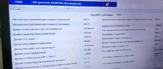
- First, connect the OBD-II scanner to the vehicle's on-board computer and read all stored data and error codes.
- Next, clear the error codes from the PCM and test drive the vehicle to see if P2241 appears again.
- If the error code appears again, check the wires and connectors.
- Test the sensor and replace if necessary.
Diagnosis and problem solving
Connect the scanner to the vehicle's diagnostic port and get all the stored codes. Then clean them and test drive the car. If the code does not appear, then the error was temporary. If it appears, continue testing.
Perform a visual inspection of the wiring and connectors associated with the oxygen sensor (HO2S). Replace damaged wiring or connectors if damage is detected. After that, reset the errors again, test drive and read them again.
If code P2241 occurs again, start the engine. Let it warm up to normal operating temperature at idle. Connect a scan tool to the diagnostic port and observe the oxygen sensor input data.
If the O₂ sensor is functioning normally, the voltage before the catalytic converter will continuously vary from 1 to 900 millivolts. The post-catalyst sensors will also cycle between 1 and 900 millivolts. A HO2S sensor that is not working properly should be considered faulty if the engine is in good working order.
If the HO2S sensor displays battery voltage or no voltage in the scanner data stream. Use a multimeter to obtain real-time data from the HO2S sensor connector. If the output remains the same, the HO2S sensor has shorted and will require replacement.
It may happen that after passing all the tests, the P2241 code is still displayed, this most likely indicates a faulty O₂ oxygen sensor. But a failed PCM module also cannot be eliminated until the sensor is replaced.
On which cars is this problem most common?
The problem with code P2241 can occur on different machines, but there are always statistics on which brands this error occurs more often. Here is a list of some of them:
- Acura
- Audi
- BMW
- Kia
- Lexus (Lexus es300, gs300, ls460, is250, rx300, rx330, rx350)
- Mazda
- Peugeot
- Toyota (Toyota Camry, Crown, Prado, Sienna, Tundra, 4runner)
- Volkswagen
With fault code P2241, you can sometimes encounter other errors. The most common ones are: P2237, P2238, P2239, P2240, P2242.
Camry
Camry error codes help, using computer diagnostics, to make the correct “diagnosis”, to understand which element, motor sensor, gearbox, etc. has failed. This significantly speeds up car repairs. Modern scanners independently decipher error codes, but if you use diagnostic equipment that does not do this, we will try to help.
Conclusion
It should be remembered that, first of all, diagnostic error codes are informational in nature about an area of the car that has failed, but are in no way a guide to action. Knowing what the electric signal means, the owner of a Toyota Camry can carry out some repair work on his own. But it is better to entrust full-fledged car repairs to a qualified and experienced technician.
- Tweet
- Share 0
- +1
- LinkedIn 0
Top
Proper diagnostic work on Camry 50
The sequence for reading the error code is approximately the same for all Toyota cars:
- with the ignition off, connect the scanner to the diagnostic connector,
- establish a connection between the scanner and the phone via Bluetooth, if the diagnostic program is installed as an application on the smartphone; connect the scanner to a laptop computer on which the diagnostic program is installed,
- in the program menu to read the error code, select the Toyota Camry of the required year and body,
- turn on the ignition or start the engine and start scanning,
- the program will display error codes that have been stored in the vehicle control units since the last time the fault codes were deleted,
- delete all errors, drive the car for 2-3 kilometers and read again, now the equipment will show only existing problems, and not all, including those that have been resolved,
- write down the error codes, if the program decrypts, then write down or save the problems shown,
- After completing diagnostic operations, turn off the scanner and ignition.
After the manipulations have been performed, analyze the information received and troubleshoot.
We carry out computer diagnostics
To test the components and assemblies of the Toyota Land Cruiser Prado 120 for possible errors, scanning devices are used. Accurate results are provided by specialized dealer scanners. In addition to them, there are universal devices. The simpler the scanner, the more likely it is that it will not recognize Prado 120 specific errors. However, most faults will be deciphered.
Faults are read using the same algorithm:
- Stop the engine and turn off the ignition.
- Connect the scanner to the Prado 120 diagnostic connector.
Now you can analyze the errors and take measures to eliminate them.
Modern scanners
There are now many scanners available for reading car error codes that completely decipher error codes. These programs are translated into Russian, are easy to use and allow you to configure vehicle parameters. For example, the time when the headlights go out after turning off the ignition, after how many seconds the lights in the cabin go out when boarding, disembarking, and more.
The car owner should think about purchasing diagnostic equipment. Not bad manufacturers of diagnostic devices: Launch, ELM, Autel, Autocom, Carman.
More category errors
B2784B2785B2786B2789B278AB278CB2790B2791B2793B2794B2795B2796B2797B2798B2799B279AB0100/13B0101/14B0102/11B0103/12B0105/53B0106/5 4B0107/51B0108/52B0111/44B0112/41B0113/42B0115/47B0117/45B0118/46B0130/63B0131/64B0132/61B0132/62B0133/62B0135/73B0136/74B013 7/71B0138/72B1000/31B1100/ 31B1140/32B1141/33B1156/15B1157/15B1158/16B1159/16B1411/11B1412/12B1413/13B1421/21B1422/22B1423/23B1424/24B1441/41B1442/42B 1443/43B1446/46B1451/51B1471/71B1472/72B1473/73B1474/74B1475/75B1476/76B1477/ 77B1497/97B1498/98B1499/99B1602/83B1603/83B1607/84B1608/84B1610/13B1612/83B1613/83B1615/14B1617/84B1618/84B161A/8AB1620/21B1 622/81B1623/81B1625/22B1627/82B1628/82B1630/23B1632/81B1633/81B1635/24B1637/ 82B1638/82B1642/81B1643/81B1647/82B1648/82B1650/32B1653/35B1655/37B1656/38See all errors →
Toyota Camry 40 error codes
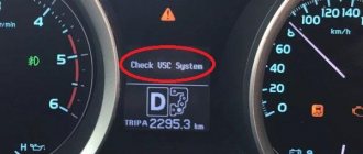
The Check VSC System notification itself does not carry specific information; it is a warning that something is wrong with the car. There may not be any significant problems, for example, if you refuel with the engine running, or you have recharged a dead battery, Check VSC System will appear. If there is no breakdown, the message will go away, turn off and start the car 10 times or disconnect the terminal from the battery for 5 minutes. The notification does not go away, then carry out computer diagnostics of the Camry.
P0351, P0352, P0353, P0354, P0355, P0356
Ignition coil errors, the last two can only appear on Toyota V6 engines, for example, 2GR-FE.
Reasons for these codes:
- faulty ignition coil,
- faulty wiring leading to the coils,
- broken electronic control unit.
To accurately determine the malfunction, use an oscilloscope to measure the electrical signal from the ignition coil that showed the error. If you don't have an oscilloscope, you can swap the potentially faulty coil with another. For example, there is an error P0351, we moved the coil from the first cylinder to the second, now the scanner shows P0352 - the problem is in the coil, but if the code remains the same P0351 - the wiring or ECU is faulty.
P0172
Error P0172 - Air/fuel mixture too rich. Causes:
- air intake system,
- faulty injectors,
- not working correctly mass air flow sensor,
- fuel pressure is outside acceptable limits,
- exhaust gas leak,
- the problem is in the circuit or in the oxygen sensor itself,
- ECU.
To make an accurate diagnosis, contact an experienced specialist.
One option to eliminate the error is to replace the VVT-I valve.
P2237
P2237 – open circuit in the oxygen sensor (A/F) pumping current circuit, P2238 – low current in the oxygen sensor (A/F) pumping current circuit (1 row 1). We are talking about a lambda probe installed before the catalyst, which is located next to the engine. This error may not affect the behavior of the car, but fuel consumption will increase. We would like to warn against replacing this sensor with a non-original one.
The lambda probe, located before the catalyst near the engine, is replaced only with the original one. The second sensor installed after the catalytic converter can be replaced with a universal one.
Using this head will allow you not to remove the heat shield when replacing failed lambda probes.
P0137, P0157
P0137, P0157 – low voltage in the oxygen sensor circuit (bank 1, bank 2 sensor 2).
Causes of errors P0137, P0157:
- open circuit, break in the heated oxygen sensor circuit, row 1,2 sensor 2,
- faulty lambda probe (heated oxygen sensor),
- air/fuel mixture sensor bank 1,2 sensor 1,
- leakage from the exhaust gas system.
During active air-fuel ratio control, if the target ratio is rich but the heated oxygen sensor output voltage is less than 0.21 V (lean), the ECM treats this as an excessively low sensor output voltage and sets DTC P0137 or P0157. During active air-fuel ratio control, if the target ratio is lean but the output voltage is greater than 0.59 V (rich), the ECM considers this to be an excessively high sensor output voltage and sets DTC P0138 or P0158.
If replacing the sensor did not bring results, then the technicians could have replaced the wrong sensor (this happens often), or the problem is not in the sensor, but in the circuit or in an exhaust gas leak.
Check all connectors; they may have oxidized or moisture may have gotten into them. Visually inspect the wiring to see if its integrity is damaged. If the circuit is visually in order, then check its operation using an oscilloscope.
Diagnosis of errors Prado 150
Prado
The control units record incorrect operation, system failures and Prado 150 errors. Self-diagnosis, carried out manually, can reveal the severity of the problem and decipher the Prado 150 error codes.