During the computer check, a special built-in device is used - a diagnostic connector.
At the same time, the quality of operation of the injection engine, gearbox, electronic sensors, security system and other actuators is diagnosed. Errors recorded on the electronic control unit (ECU) are analyzed.
Error Codes Toyota Camry 30
error codes for car malfunctions, self-diagnosis, error interpretation in Russian
1 Toyota Camry error codes 30 1.1 P0500 Toyota Camry ACV30
1.2 How to reset “CHECK ENGINE” on a Toyota Camry? / How to reset the “check” on the Toyota Camry?
Short circuit to B+ in the ABS motor relay circuit
Open circuit in the ABS electromagnetic valve relay circuit
Short circuit to B+ in the ABS solenoid valve relay circuit
Brake actuator control unit assembly
SM Solenoid Valve Circuit
Foreign particles on the tip of the right front speed sensor
4. Brake actuator control unit (anti-skid control unit)
Foreign particles on the tip of the left front speed sensor
4. Brake actuator control unit (anti-skid control unit)
Foreign particles on the tip of the right rear speed sensor
4. Flea catching by the working cylinders of the brake assembly (anti-skid system ECU)
Foreign particles on the tip of the left rear speed sensor
4. Brake actuator control unit (anti-skid control unit)
Low positive battery voltage
Jam in the acceleration sensor
Open or short circuit in the deceleration sensor circuit
Acceleration sensor output abnormal
Malfunction of the pressure sensor in the main cylinder
Open circuit in the brake light switch target
P0500 Toyota Camry ACV30
Algorithm for finding a breakdown (error P0500)
How to reset “CHECK ENGINE” on a Toyota Camry? / How to reset the “check” on the Toyota Camry?
Toyota car using some simple manipulations.
4. Brake actuator control unit (anti-skid control unit)
Open circuit in the pump motor circuit
Weak output signal from the right front speed sensor (in active diagnostic mode)
Weak output screen of the left front speed sensor <8 in active diagnostic mode)
Weak output signal from the right rear speed sensor (in active diagnostic mode)
Weak output signal from the left rear speed sensor (in active diagnostic mode)
Abnormal change in the output signal of the right front speed sensor (in active diagnostic mode)
Abnormal change in the output signal of the left front speed sensor (in active diagnostic mode)
Abnormal change in the output signal of the right rear speed sensor (in active diagnostic mode)
Abnormal change in left rear speed sensor output signal (during active diagnostic mode)
Skid control ECU malfunction
Brake actuator control unit (skid control ECU)
Right front wheel speed sensor circuit
Left front wheel speed sensor circuit
Right rear wheel speed sensor circuit
Left rear wheel speed sensor circuit
Short circuit in the ABS engine emergency mode circuit
Inadmissible supply voltage to the acceleration and/or yaw rate sensor
Control unit data bus is disabled
CAN data transmission system
Lost communication with lateral acceleration sensor
CAN communication system (between skid control ECU and deceleration and yaw rate sensor)
*1, *2 - even after troubleshooting, the ABS warning lamp turns off only after performing the following operations: (*1):
How to read errors?
The procedure for reading codes consists of the following steps:
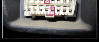
- After turning off the engine, a special scanner must be connected to the diagnostic connector, which is located in the fuse block.
- Next, the scanner should be connected to a laptop or computer on which special software for self-diagnosis is installed. If this software is installed on a smartphone, then the action consists of connecting via bluetooth.
- Further work takes place in the program environment - in the menu you need to select Toyota Camry, year of manufacture and body.
- Then you need to start the car or turn on the ignition, in this position you can start scanning the codes.
- The result of the scan will be a list of error codes that will appear on the display of your laptop or smartphone. These errors were recorded since the last time the register was deleted - that is, the information is out of date. Carrying out correct diagnostics requires formatting the memory - all displayed errors should be deleted.
- After clearing the memory of the on-board system in the car, you need to drive 2-3 kilometers, and then read it again - now the list of errors will include only “fresh” codes.
- The last step will be saving and deciphering the codes.
Toyota Camry 40 error codes
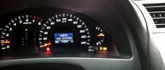
Check VSC System - a message appears on the on-board computer screen.
The Check VSC System notification itself does not carry specific information; it is a warning that something is wrong with the car. There may not be any significant problems, for example, if you refuel with the engine running, or you have recharged a dead battery, Check VSC System will appear. If there is no breakdown, the message will go away, turn off and start the car 10 times or disconnect the terminal from the battery for 5 minutes. The notification does not go away, then carry out computer diagnostics of the Camry.
P0351, P0352, P0353, P0354, P0355, P0356
Ignition coil errors, the last two can only appear on Toyota V6 engines, for example, 2GR-FE.
Video
Computer diagnostics of Toyota Camry 40 cars is a powerful tool in determining the location of a car malfunction.
Diagnostics must be performed when the on-board computer message “Check VSC System” appears.
ATTENTION! A completely simple way to reduce fuel consumption has been found! Don't believe me? An auto mechanic with 15 years of experience also didn’t believe it until he tried it. And now he saves 35,000 rubles a year on gasoline! Read more"
To carry out diagnostic work, specialized (dealer) or universal equipment is required. As a result of diagnosing the devices of the Toyota Camry 40, error codes are issued. Most car scanners independently decipher error codes.
Description of the self-diagnosis process
First you need to check that the battery has a voltage of at least 11 volts, the throttle valve is closed, and all electrical appliances are turned off. For convenience, you also need to prepare a homemade jumper from a metal clip or wire.
The error is indicated by two numbers: the first is counted by the number of blinking indicator lights every 0.5 seconds, then a break, the second is also counted by the number of blinks with an interval of 0.5 seconds. After 2.5 seconds, the next code is issued, etc. When all codes have been issued, after a break of 4.5 seconds, the codes are issued again. If there are no errors, the interval between signals is 0.25 seconds.
Two-digit ABS codes are deciphered using special tables.
P0137, P0157
P0137, P0157 – low voltage in the oxygen sensor circuit (bank 1, bank 2 sensor 2). Causes of errors P0137, P0157:
New and Old Lambda Sensor If, during active air-fuel ratio control, the target ratio is rich but the heated oxygen sensor output voltage is less than 0.21 V (lean), the ECM treats this as an excessively low sensor output voltage and sets DTC P0137 or P0157 . During active air-fuel ratio control, if the target ratio is lean but the output voltage is greater than 0.59 V (rich), the ECM considers this to be an excessively high sensor output voltage and sets DTC P0138 or P0158.
If replacing the sensor did not bring results, then the technicians could have replaced the wrong sensor (this happens often), or the problem is not in the sensor, but in the circuit or in an exhaust gas leak. Check all connectors; they may have oxidized or moisture may have gotten into them. Visually inspect the wiring to see if its integrity is damaged. If the circuit is visually in order, then check its operation using an oscilloscope.
Catalog number 1 of the oxygen sensor installed before the catalyst.
Self-diagnosis of climate control for Toyota Camry ACV40.
1. Stop the engine. 2. Simultaneously press and hold the “AUTO” and “Internal air circulation” buttons on the climate control. 3. Turn on the ignition. After checking the indicators, sensor diagnostics will automatically begin. 4. The result of the sensor diagnostics is displayed in the window displaying the set temperature. If there are 2 or more codes, the display starts with the smallest one. 5. To diagnose the drives, press the “Internal air circulation” button. Checking the drives should be carried out on a warm engine. To slow down the test, press the heated front window button. At intervals of 1 second. the damper actuators, fan and relay will operate. To enter the sensor diagnostic mode, press “AUTO”. 6. To complete the diagnostics, press the “OFF” button. Memory clearing:
After troubleshooting, clear the memory: while diagnosing the sensors, press the “Heated front window” (FRONT) and “Heated rear window” (REAR) buttons simultaneously.
Here's what you need to click to diagnose!
Error codes:
00
- No errors
11
- Cabin temperature sensor
* 12
- Ambient temperature sensor
* 13
- Evaporator temperature sensor
* 14
- Coolant temperature sensor
* 21
- Sunlight sensor (passenger side)
* 22
- Lock sensor compressor
** 23
- Pressure sensor (refrigerant).
*** 24
- Sunlight Sensor (driver's side)
* 31
- Air Mixture Damper Position Sensor (passenger's side)
* 32
- Air Intake Damper Position Sensor
* 33
Outlet Damper Position Sensor Circuit
41
- Air Mixture Damper Servo Motor (with passenger side)
* 42
Damper
Control Servo Motor
46 -
Air Damper Control Servo (driver's side)
51
- Compressor Solenoid Circuit
62 -
Air Humidity Sensor (not on Camry)
71
- A/C Inverter High Voltage Power Resource System Malfunction
72
- A/C Inverter High Voltage Output System Malfunction
73
- A/C Inverter Start-up Signal System Malfunction
75
- A/C Inverter Cooling / Heating System Malfunction
76
- A/C Inverter Load System Malfunction
77
- A/C Inverter Low Voltage Power Resource System Malfunction
97
- BUS IC Communication Malfunction
98
- Communication Malfunction (A/C Inverter Local)
99
- Multiplex Communication Circuit
Note: *:
This sensor or climate control unit is faulty;
The wiring or connectors between this sensor and the climate control are damaged. **:
This sensor or climate control unit is faulty;
The wiring or connectors between this sensor and the climate control are damaged; The compressor drive belt is damaged or not adjusted; The compressor electromagnetic clutch sensor is faulty; The air conditioning compressor is faulty (or the compressor is blocked); The engine control module (ECM) is faulty. ***:
This sensor or climate control control unit is faulty; The wiring or connectors between this sensor and the climate control are damaged; The compressor is faulty (or the compressor is blocked); Leakage, lack of refrigerant or incorrect (lower or higher than normal) pressure in the system. Codes 21 and 24 can pop up if diagnostics are carried out in a dark room or at night. Due to loss of connection with the instrument panel, code 71 cannot be displayed on it. What is “compressor blocking”? Many people do not understand this point. The principle of correct operation is simple. When the compressor is OFF, the accessory drive belt rotates only the accessory drive belt pulley. If the compressor needs to be turned ON, the electromagnetic clutch is activated (the compressor is locked with the pulley and begins to rotate). The brain receives a signal from a sensor (similar to the ABS sensor) that the compressor is turned on and rotating. This sensor then transmits pulses to the ECM, the number of which is equal to the engine speed. If the ratio between the compressor and engine speeds deviates by 20% or more from normal operating speeds, the ECM will turn off the air conditioning compressor and the indicator will flash periodically.
1 p. Data on the operating status of the compressor is transmitted by the ECM to the air conditioning control unit via a multiplex data transmission system (CAN and BEAN buses).
Conditions for Error P0110
Appearance and location of DTVV
To understand the conditions for the occurrence of an error, let’s take a closer look at the operating principle of the intake temperature sensor and the functions it performs. Its main task is to control the temperature of the intake air. The operation of the sensor is based on a thermistor built into its body, which changes its electrical resistance depending on the intake air temperature.
If said temperature decreases, then the resistance increases. When it gets higher, the resistance value drops . The resulting electrical signals are sent to the ECM, that is, the electronic control module. Based on this data, the electronics makes a decision to increase or decrease the fuel injection volume at cold or warm air temperatures surrounding the vehicle.
Self-diagnosis of Toyota Camry sv30
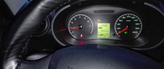
The ECM contains a built-in self-diagnosis system that detects and recognizes malfunctions. When a fault occurs, the check engine light comes on, the fault is identified and a diagnostic code is recorded. The check engine warning light, located on the instrument cluster, comes on when the ignition is turned on. After the engine starts, the check engine light should go out. If the lamp remains on after starting the engine, there is a malfunction in the electronic system.
What do the codes mean?
The table below shows the most common errors in Toyota Camry.
| Error codes | Meaning | Reasons for appearance |
| P035(1,2,3,4,5,6) | Problems with the ignition coil (P0355 and P0356 can only occur on V6 engines). | This may be a signal that the wiring is faulty, the ignition coil is not working, or the control unit is not functioning. |
| P0172 | Over-rich fuel mixture. | Incorrect operation of sensors, insufficient compression, incorrect gas distribution, deformation, loss of seal integrity. |
| P0137, P0157 | Low voltage to oxygen sensor. | Open circuit, broken lambda probe, exhaust gas leak. |
| P2237(8) | Weak current or interruption of current to the lambda sensor. | Open or short circuit in the sensor circuit. |
Self-diagnosis system
general information
1, The self-diagnosis function is built into the electronic control unit of the automatic transmission. Using the overdrive indicator, the system informs about a malfunction that has occurred in the automatic transmission. In addition, using this indicator you can determine the fault code that has occurred. Note: Warning signals and trouble codes can only be read when the overdrive switch is in the “ON” position. If the switch is in the “OFF” position, the indicator lamp lights up without blinking.
a) If there is a malfunction in the speed sensor, throttle position sensor or solenoid valves, the indicator will flash to alert the driver that a malfunction has occurred. But if there is a malfunction in the torque converter lock-up solenoid valve, there will be no warning about the malfunction. b) Fault codes can be read by the number of flashes of the overdrive indicator; to do this, you need to short-circuit the “TE1” and “E1” terminals of the diagnostic connector.
c) The diagnostic system does not detect failure of the throttle position sensor and brake light switch, but they can be checked by measuring the voltage at the “TT” terminal of the diagnostic connector.
Table. Fault codes.
Speed sensor - broken wiring or short circuit
The car moves in any selector position other than “N” or “P” for more than 30 seconds
Solenoid valve No. 1 - broken wiring or short circuit
Vehicle speed is more than 10 km/h.
No. 2 - broken wiring or short circuit
Vehicle speed is more than 10 km/h.
Airbag fault codes
If there is a message on the dashboard about a malfunction of the airbag system, you should definitely check which elements and sensors are faulty or there is no communication with them. The resistance of the airbag and belt pretensioner squib can be checked with a multimeter, it is about 2 ohms. Error codes with explanations are given in the table.
How to perform computer diagnostics on Camry 40
Various scanners are used to diagnose blocks and components of Toyota Camry v40 cars. Optimal scanning is performed using dealer devices. You can use universal professional and semi-professional diagnostic devices. Engine diagnostics can be performed using simple scanners such as ELM327.
In this case, some specific errors in the engine management system may not be detected. Common errors in the OBDII protocol will be fully identified. In most cases, this is enough to identify most faults.
The sequence of diagnostic work is approximately the same for all devices:
ABS fault codes, possible faults
ABS system error codes make repairs much easier. If the anti-lock brake system malfunction indicator light comes on, it means that it has become completely inoperable. Continuing to drive, especially on slippery roads, is dangerous. In most cases, the cause of the malfunction may be the failure of one of the sensors. If the error code shows a malfunction in the circuit of any sensor, for example, the rear left one, again, you should not immediately start replacing it. Most often this is due to damage to the electrical wiring leading to it. Sometimes there are up to three wiring faults along the way to the rear sensors.
If the error code corresponds to an incorrect signal value for a particular sensor, the working area may be dirty, or the gap may be increased due to small stones.
Before replacing the sensor, it should be tested using a multimeter. The working sensor has a resistance in one of the directions from 700 to 1500 Ohms.
Below are error codes with explanations and possible malfunctions.
Modern scanners
There are now many scanners available for reading car error codes that completely decipher error codes. These programs are translated into Russian, are easy to use and allow you to configure vehicle parameters. For example, the time when the headlights go out after turning off the ignition, after how many seconds the lights in the cabin go out when boarding, disembarking, and more.
The car owner should think about purchasing diagnostic equipment. Not bad manufacturers of diagnostic devices: Launch, ELM, Autel, Autocom, Carman.
Toyota Camry 40 error codes
Check VSC System - a message appears on the on-board computer screen.
The Check VSC System notification itself does not carry specific information; it is a warning that something is wrong with the car. There may not be any significant problems, for example, if you refuel with the engine running, or you have recharged a dead battery, Check VSC System will appear. If there is no breakdown, the message will go away, turn off and start the car 10 times or disconnect the terminal from the battery for 5 minutes. The notification does not go away, then carry out computer diagnostics of the Camry.
P0351, P0352, P0353, P0354, P0355, P0356
Ignition coil errors, the last two can only appear on Toyota V6 engines, for example, 2GR-FE.
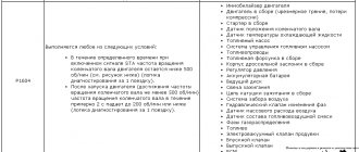
Reasons for these codes:
To accurately determine the malfunction, use an oscilloscope to measure the electrical signal from the ignition coil that showed the error. If you don't have an oscilloscope, you can swap the potentially faulty coil with another. For example, there is an error P0351, we moved the coil from the first cylinder to the second, now the scanner shows P0352 - the problem is in the coil, but if the code remains the same P0351 - the wiring or ECU is faulty.
Proper diagnostic work on Camry 50
Diagnostic connector in Camry 30
The sequence for reading the error code is approximately the same for all Toyota cars:
- with the ignition off, connect the scanner to the diagnostic connector,
- establish a connection between the scanner and the phone via Bluetooth, if the diagnostic program is installed as an application on the smartphone; connect the scanner to a laptop computer on which the diagnostic program is installed,
- in the program menu to read the error code, select the Toyota Camry of the required year and body,
- turn on the ignition or start the engine and start scanning,
- the program will display error codes that have been stored in the vehicle control units since the last time the fault codes were deleted,
- delete all errors, drive the car for 2-3 kilometers and read again, now the equipment will show only existing problems, and not all, including those that have been resolved,
- write down the error codes, if the program decrypts, then write down or save the problems shown,
- After completing diagnostic operations, turn off the scanner and ignition.
After the manipulations have been performed, analyze the information received and troubleshoot.