From english:
Decoding the error P1305 from Toyota: Engine Coolant Temperature Circuit Low Input
Make:
Toyota
Code:
P1305
Definition:
Engine Coolant Temperature Circuit Low Input
Description:
Monitor runs whenever the following DTCs are not present: None Engine coolant temperature sensor voltage: Less than 0.14 V
Cause:
- Short in ECT sensor circuit
- ECT sensor
- ECM
Engine fault codes and methods for erasing them
Fault codes for gasoline engines (Toyota)
12 - Crankshaft position sensor (P0335) 13 - Crankshaft position sensor (P0335, P1335) 14 - Ignition system, coil No. 1 (P1300) and No. 4 (P1315) 15 - Ignition system, coil No. 2 (P1305) and No. 3 (P1310) 16 - Automatic transmission control system 18 - VVT-i system - phases (P1346) 19 - Accelerator pedal position sensor (P1120) 19 - Accelerator pedal position sensor (P1121) 21 - Oxygen sensor (P0135) 22 - Coolant temperature sensor fluid (P0115) 24 - Intake air temperature sensor (P0110) 25 - Oxygen sensor - lean signal (P0171) 27 - Oxygen sensor No. 2 31 - Absolute pressure sensor (P0105, P0106) 34 - Turbocharging system 35 - Turbo pressure sensor 36 - CPS sensor (P1105) 39 - VVT-i system (P1656) 41 - Throttle position sensor (P0120, P0121) 42 - Vehicle speed sensor (P0500) 43 - Starter signal 47 - Additional throttle position sensor 49 - Pressure sensor fuel (D-4) (P0190, P0191) 51 - Switch status 52 - Knock sensor (P0325) 53 - Knock signal 55 - Knock sensor No. 2 58 - SCV actuator (D-4) (P1415, P1416, P1653) 59 - VVT-i signal (P1349) 71 - EGR system (P0401, P0403) 78 - Injection pump (D-4) 89 - ETCS drive (P1125, P1126, P1127, P1128, P1129, P1633) 92 - Cold start injector (D-4 ) (P1210) 97 - Injectors (D-4) (P1215)
More category errors
P1310P1315P1320P1325P1330P1335P1340P1341P1342P1343P1345P1346P1349P1350P1351P1354P1400P1401P1405P1406P1410P1411P1420P1421P142 2P1423P1430P1431P1436P1437P1440P1441P1442P1443P1444P1445P1450P1451P1452P1453P1455P1500P1510P1511P1512P1520P1521P1525P1550P155 1P1552P1566P1571P1572P1575P1578P1600P1602P1605P1607P1613P1614P1615P1616P1617P1630P1631P1633P1636P1637P1645P1646P1647P1652P165 6P1658P1661P1662P1663P1690P1692P1693P1700P1705P1715P1725P1730P1735P1740P1755P1760P1765P1770P1780P1781P1782P1783P1790P1810P183 5See all errors →
How to diagnose an engine?
Toyota Corolla self-diagnosis will allow you to figure out the source of problems in your car. Let's figure out where to start, what the error codes are and how to carry out diagnostics without special instruments and tools right in the garage.
First thing
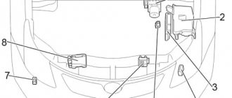
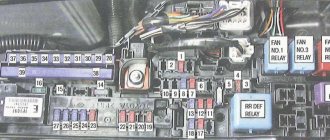
All Toyota models older than 1988 are equipped with a multi-pin connector for diagnostics, which is located under the hood near the battery or on the left side of the car (along the way). The connectors are called DLC-1 and DLC-2. Option with index 1 is a plastic box, which is often marked “Diagnostic”. In this case, error codes are displayed directly through the “check” icon, located in a visible place for the driver. If you have a restyled or modern model of Toyota Corolla, then the light bulb is in the form of an engine, but it is the same thing. The previous information concerned owners of gasoline cars, since for diesel versions, instead of a separate light bulb, a glow plug is used: a picture in the form of a spiral.
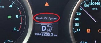
After carrying out diagnostics on your own, errors in the event of an automatic transmission malfunction are displayed through the “AT Check”, “Power” or “OD” lamps. Failures in other systems, for example, TRS or SRS and ABS, are displayed on the corresponding lamps.
Errors in cars from different manufacturers
AcuraAlfa RomeoAudiBMWBuickCadillacChevroletChryslerDaewooDodgeEagleFIATFordGeneral MotorsGeoGMCGreat WallHondaHUMMERHyundaiInfinitiIsuzuIVECOJaguarJeepKiaLamborghiniLand RoverLexusLincolnMazdaMercedes BenzMercuryMINIMitsubishiNissanOldsmobileOpelPeugeot/C itroenPlymouthPontiacPorscheRAMRenaultSaabSaturnScionSubaruSuzukiToyotaVolga SiberVolkswagenVolvoVAZ (LADA)GAZ (GAZ)GAZ (Mikaz 11)GAZ (Mikaz 7.6)UAZ (Bosh ME17)UAZ Patriot (IVECO diesel)
Poll: Were you able to diagnose the problem? (Number of votes: 20)
Yes, in person
Yes, with the help of a friend
Yes, from an official dealer
No
To vote, click on the desired answer.Results
Tell your friends:
Please rate, this is very important for us:
Votes: 0 people Rating: 0 out of 5.
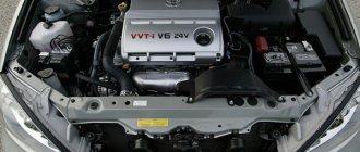
16 Toyota Corolla 2001-2003 Malfunctions of the “amplifier module” circuit code P1300 P1305 P1310 P1315 P1300 P1305 P1310 P1315 Malfunctions of the “amplifier module” circuit (no 1)A direct ignition system (dis) is used. The direct ignition system increases the accuracy of determining the ignition timing, reduces the loss of electrical charge, and generally improves the reliability of the ignition system by eliminating the ignition distributor link
Dis is a single-cylinder ignition system in which one cylinder is ignited from one ignition coil. In a single-cylinder ignition system, the spark plug is mated to the end of the secondary winding. The high-voltage discharge generated in the secondary winding goes directly to the spark plug. The spark from the spark plug goes from the center electrode to the ground electrode.
The electronic engine control module (ecm) sets ignition timing and provides the ignition signal (igt) for any cylinder. Based on the Igt signal, the power transistors cut off the current going to the primary winding in the ignition coil. At the same time, the igniter sends an ignition confirmation signal (igf) to the electronic engine control module (ECM) as an additional safeguard against failure.
DTC No
| Diagnosis Condition DTC | Possible failure point | |
| P1300 P1305 P1310 P1315 | When the engine is running, the engine electronic control module (ECM) does not receive an ignition confirmation signal (IGF). | · Ignition system · Open or short circuit in the ignition signal circuit (IGT) from the ignition coil with “amplifier module” · Ignition coils with “amplifier module” · ECM |
If there is news of a malfunction with code Dtc P1300, check the ignition coil No.. and the “amplifier module” electrical circuit. If there is news of a malfunction with code Dtc P1305, check the ignition coil No.. and the “amplifier module” circuit. If there is news of a malfunction with DTC P1310, check the ignition coil No.. and the “amplifier module” circuit. If there is news of a malfunction with DTC P1315, check the ignition coil No.. and the “amplifier module” circuit. Check the indicator display using a hand-held diagnostic tool. The indicator panel stores information about engine operation when a malfunction is detected, therefore, when searching for breakdowns, it is advisable to know whether the vehicle was moving or stopped, whether the power unit was heated or not, whether the fuel-air mixture was lean or enriched, etc. , at the time of the malfunction. Check the spark and ignition Check the cable harness and terminals (ecm - ignition coil)
The following measurement operation is predefined for cylinder No. 1. If a fault occurs in another cylinder, it can be checked by following the same procedure.
(a) Separate the ignition coil plug. (b) Separate the E19 Ecm plug. (c) Check for an open circuit between the Igf terminal of the Ecm connector and the Igf terminal of the ignition coil connector. Resistance: no more than 1 Ohm (d) Check for an open circuit between terminals Igf and E2 of the Ecm plug. Resistance: not less than 1 mOhm
Check Ecm (check voltage) (a) Separate the ignition coil plug. (b) Turn the ignition on. (c) Check the voltage between terminals Igf and E2 of Ecm plug. Voltage: 4.5 - 5.5 V Change the ignition coil Check and change the Ecm
(a) Separate the ignition coil plug. (b) Separate the E19 Ecm plug. (c) Check for open circuit between terminal Igt1 of the Ecm connector and terminal Igt of the ignition coil connector. Resistance: no more than 1 ohm (d) Check for short circuit in the circuit between terminals Igt1 and E2 of the Ecm plug. Resistance: not less than 1 mOhm
(a) Turn on the ignition. (b) Check the voltage between terminals Igt1 - Igt4 and terminal E2 of the Ecm plug while cranking. Voltage: more than 0.1V and less than 4.5V
When cranking the crankshaft or idling, check the signalgram between terminals Igt1 - Igt4 and E2 of the Ecm connector
When cranking or idling, the correct waveform with rectangular curves is shown in the figure on the right side.
(a) Separate the ignition coil plug from the “booster module”. (b) Turn the ignition on. (c) Check the voltage between terminals Igt1 - Igt4 and terminal E2 of the Ecm plug while cranking. Voltage: more than 0.1V and less than 4.5V
Check the ignition coil (power supply) (a) Separate the ignition coil plug from the “booster module”. (b) Turn the ignition on. (c) Check the voltage between terminals +b and Gnd of the ignition coil plug. Voltage: 9 - 14 V
(a) Separate the ignition coil plug from the “booster module”. (b) Separate the ignition switch plug. (c) Check for an open circuit between terminal +b of the ignition coil plug with the “amplifier module” and terminal Ig2 of the ignition toggle switch plug. Resistance: no more than 1 ohm Replace the ignition coil
Next page""""""
- 10. 11. 12. 13. 14. 15. 16. 17. 18. 19. 20. 21. 22. 23. 24. 25. 26. 27. 28. 29. 30. 31. 32. 33. 34. 35. 36. 37. 38. 39. 40. 41. 42. 43. 44. 45. 46. 47. 48. 49. 50. 51. 52. 53. 54. 55. 56. 57. 58. 59.60. 61. 62. 63. 64. 65. 66. 67. 68. 69. 70. 71. 72. 73. 74. 75. 76. 77. 78. 79. 80. 81. 82. 83. 84. 85. 86. 87. 88. 89. 90. 91. 92. 93. 94. 95. 96. 97. 98. 99. 100. 101. 102. 103. 104. 105. 106. 107. 108. 109. 110. 111. 112. 113. 114. 115. 116. 117. 118. 119. 120.121. 122. 123.124.125.126.127.128.129.130.131. 132.133.134. 135.136.137.138.139.140.
coming
Two-digit system codes
11 — lack of power supply to the valve control unit; 12 and 13 - no engine speed signal is received; 14 - no feedback is received from the negative contact of the ignition coil or, if there are two of them, then from coil No. 1; 15 - no feedback from the negative contact of ignition coil No. 2; 16 - no signal is received from the automatic transmission ECU;
17 and 18 - unacceptable value of camshaft position No. 1 and No. 2; 21 — incorrect signal from the oxygen level sensor; 22 - unacceptable temperature value of the power unit; 23 and 24 - incorrect indicator of intake air temperature; 25 — lean air-fuel mixture; 26 - too rich air-fuel mixture;
27, 28 and 29 - incorrect signal from the additional oxygen sensor; 31 — unacceptable value of air flow or pressure of the intake manifold; 32 — incorrect response of the air flow sensor; 34 — boost malfunction; 35 — unacceptable value of intake manifold pressure (vacuum sensor); 38 - incorrect signal from the fluid sensor in the automatic transmission;
41 — incorrect response of the throttle position sensor; 42 - unacceptable value of the speed that the car develops; 43 - lack of starter signal on the engine ECU; 46 - malfunction of solenoid valve No. 4 or its circuit; 47 - breakdown of the additional sensor that fixes the position of the throttle or its circuit;
48 — malfunction of the additional fuel supply system; 51 - there is no idle signal from the sensor displaying the throttle position; 52 and 55 - incorrect feedback from the knock sensor; 53 - failure of the knock sensor control circuits; 61 - malfunction of the speed sensor and its circuit;
62-65 - malfunction of solenoid valves No. 1-4 or the corresponding circuit; 67 - malfunction of the O/D switching sensors or its circuit; 71 — breakdown of the exhaust gas recirculation system; 72 - malfunction of the fuel cut-off solenoid; 77 - malfunction of the pressure control solenoid or its circuit (in automatic transmission);
78 - there is no signal from the fuel pump or a malfunction of its circuits; 81—85 — malfunction of circuits in various parts of the robot box; 86 - breakdown of sensors that record engine speed; 88 - malfunction of the electrical circuit between the power plant control units and the automatic transmission; 89 — malfunction of the electrical circuit between the power plant control units and the robot box;
99 - no faults. Decoding engine fault codes for type 10: 1 - normal operation; 2 — unacceptable air flow value; 3 — incorrect switch signal; 4 - unacceptable antifreeze temperature value; 5 — incorrect oxygen sensor signal; 6 — unacceptable engine speed;
11 — presence of an open circuit in the solenoid relay; 12 - solenoid relay circuit closed; 13 — presence of an open circuit in the pump motor control relay; 14 — circuit closure of the pump motor control relay; 15—18 — presence of disturbances in the operation of the TRC solenoid control; 21—24 — violation of the wheel solenoid circuit;
25—27 — violation of the TRC solenoid circuit in different parts of the circuit; 31—34 — incorrect signal from wheel speed sensors; 35 and 36 - open circuit of wheel speed sensors; 37 - malfunction of the rotors installed on the sensors displaying the speed of the rear wheels; 41 — too high or low supply voltage; 43 - deviation in the operation of the deceleration sensor;
44 - malfunction of the deceleration or neutral sensor circuits; 45-49; 58 and 61 - breaks and malfunctions of TRS circuits and parts; 51—53 — malfunction of the pump electric motor or its control; 55 - low brake fluid level or malfunction of its sensor; 56 and 57 - unacceptable oil pressure value;
Toyota diagnostics with a paper clip
I know how you can connect a Japanese car with an OBD-2 connector, but the data transfer protocol differs from the standard ISO protocols with the Torque program! For those who are not in the know: Torque allows you to turn your Android smartphone on an iPhone into a fully functional on-board computer without the need to contact super-professional electricians, as would have to be done, for example, in the case of purchasing any multitronic.
And it’s convenient to mount it - you put your mobile phone in a smartphone holder on the dashboard, and you get data from such a fun gadget that costs no more than rubles.
It displays hundreds of machine parameters in real time, creates graphs, and you can carry out easy diagnostics with it at any convenient time. Most of the parameters that are taken at the service station will also be available to you. You won’t be able to carry out serious diagnostics, but I think few people need to get into the very guts of the car, when it’s enough to look at the average fuel consumption, speed, tachometer speed, coolant temperature, engine temperature, etc. of parameters in real time.
Plus system errors, for which many go to service stations. I’ll warn you right away - there are two types of Japanese cars: That is, they were brought to our country from Europe, but they are considered Japs. The conversation with them is short - this small gadget and Torque for rubles will be enough for most cars that generally have this very OBDII protocol.
In purely Japanese models, everything is more complicated. And then the normal connection to Torque does not work. Our craftsmen from the pccar forum went the hard way and made a wonderful miracle software called ECU. At the moment there are two current models of this program that allow you to delve as deeply as possible into the depths of the car’s brains, but I personally have not tested it, since I have the necessary parameters in Torque - pictures on the right.
Let me remind you that this is only a small part of the parameters that it can display. ECU2 allows you to work with ELM laces, which, for example, allows you to save the interior from the need to use wires and get by with a laptop with Bluetooth. There is no mobile version of the application. ECU3 allows you to quickly receive diagnostic information from the car, but the disadvantage will be the need to use a special K-line cord, that is, add a wire here - obviously the car will have to stand still during diagnostics.
There are certainly advantages there, but the main drawback for me is the lack of a mobile version, because the last thing I want is to carry a laptop with me in the cabin, as well as buy expensive cords. And I installed Torque for rubles from the market. For a long time I tormented Yandex, Google, searching the pccar forum. But I never found anything.
But you can’t spend a whole day searching and not find anything, this is not my way. And I went directly to the manufacturer of this powerful software - I wrote to them on the forum - guys, you know about the problem of the Japs. Please make your software work. The answer to me was calm silence. By chance, I immediately came across a discussion of this crap on the market itself where the support sent a person with a link to their website.
I found an interesting Egg there: