Toyota Land Cruiser Prado, Lexus GX 470 repair manual
Coolant pump Removal 1. Unscrew the four bolts and remove the lower engine protection. Tightening torque……………..29.6 Nm 2. Drain the coolant. 3. Remove the top protective cover. Torque ………. 7.6 Nm 4. Unscrew the 11 bolts and remove the upper radiator support. 5. Loosen the four viscous coupling nuts. Tightening torque………………..21.4 Nm 6. Remove the timing chain. 7 Remove the cooling fan. a) Release the hose clamp and disconnect the two hoses from the fan shroud. b) Disconnect the expansion tank hose. c) Unscrew the two bolts securing the expansion tank and remove the tank.
Tightening torque ………………..5.1 Nm d) Unscrew the four nuts and remove the viscous coupling along with the fan casing. 8. Remove the coolant pump pulley. 9. Remove the ventilation system hoses. 10. Remove the air filter. 11. Remove the cooling system inlet pipe. a) Disconnect the two oil cooler hoses. b) Disconnect the two radiator hoses. c) Disconnect the five bypass hoses. d) Unscrew the five mounting bolts and remove the inlet pipe. Tightening torque…………………9.2 Nm e) Remove the O-ring. f) Remove the gasket from the coolant pump. 12. Unscrew the two bolts and remove the two intermediate pulleys. 13. Remove the generator. 14. Remove the air conditioning compressor and hang it to the side without disconnecting the hoses. 15. Unscrew the three bolts and remove the intermediate pulley near the air conditioning compressor. 16. Remove the tension pulley for the accessory drive belt. 17. Unscrew the 17 bolts and remove the coolant pump with gasket.
Check Visually check that there are no coolant leaks through the connections, the coolant channel and the air channel.
Installation 1. Install the coolant pump. a) Apply sealant to 2 or 3 turns of bolts and tighten. Note: After applying the sealant, the mating parts must be assembled within the time specified in the instructions for use of the sealant. Otherwise, the material must be removed and the sealant reapplied. b) Install the pump with a new gasket and tighten the 17 bolts. Tightening torque: 10 mm bolt ……………………………9 Nm 12 mm bolt …………………..23 Nm 2. Install the tension pulley for the accessory drive belt. 3. Install the idler pulley near the air conditioning compressor and tighten the three bolts. Tightening torque…………..25.5 Nm 4. Install the air conditioning compressor. 5. Install the generator. 6. Install two intermediate pulleys and tighten two bolts. 7. Install the cooling system inlet pipe. a) Install the O-ring. b) Install the coolant pump gasket. c) Lubricate the seal with soapy water. d) Install the inlet pipe and tighten the five mounting bolts. Tightening torque…………………..9 Nm e) Connect the five bypass hoses. f) Connect the two radiator hoses. g) Connect the two oil cooler hoses. 8. Further installation is carried out in the reverse order of removal.
Maintenance regulations
| № | list of works | mileage |
| 1 | drive belts - check, adjustment | Check every 20 thousand km. |
| 2 | Engine oil, engine oil filter | Replacement every 8-10 thousand km. |
| 3 | Coolant for engine, power steering, windshield and headlight washers - level check | Check every 10 thousand km. |
| 4 | Vehicle components and assemblies - checking for leaks and external damage | Check every 10 thousand km. |
| 5 | Radiator - checking cleanliness, checking hose connections and their correct location, corrosion, etc. | Check every 40 thousand km. |
| 6 | Exhaust systems - leak testing | Check every 20 thousand km. |
| 7 | Spark plug | Check every 100 thousand km. |
| 8 | Battery - checking charge, electrolyte level and density, terminal condition | Replace every 10 thousand km. |
| 9 | Fuel filter | Replacement every 80 thousand km. |
| 10 | Air filter | Replacement every 30-40 thousand km. |
| 11 | Fuel tank cap, fuel lines - check | Check every 40 thousand km. |
| 12 | Fuel vapor adsorber - check | Check every 40 thousand km. |
| 13 | Brake system - checking the brake pedal, condition of brake pads, discs, calipers, parking brake lever travel | Check every 10 thousand km. |
| 14 | Parking brake - check | Check every 20 thousand km. |
| 15 | Brake fluid - check, replacement | Replace every 40 thousand km. |
| 16 | Checking and replacing clutch fluid for models with manual transmission | Replace every 40 thousand km. |
| 17 | Steering - check for play, condition of boots, ease of rotation of the steering wheel | Check every 20 thousand km. |
| 18 | Drive shafts and drive shaft boots - check | Check every 10 thousand km. |
| 19 | Suspension joints, joint boots, wheel bearing play - check | Check every 10 thousand km. |
| 20 | Gear shift lever for models with 6-speed manual transmission | Check every 30 thousand km. |
| 21 | Transmission oil - check for models with manual transmission | Check and replace every 40 thousand km. |
| 22 | Checking the fluid for the Multidrive S | Check and replace every 40 thousand km. |
| 23 | Tires - checking condition and pressure | Check every 10 thousand km. |
| 24 | External and internal lighting devices | Check every 10 thousand km. |
| 25 | Cabin filter | Replace every 10 thousand km. |
| 26 | Air conditioning systems checking freon level | Check every 20 thousand km. |
Fuses and relays Toyota Land Cruiser Prado 120
The cars considered were Toyota Land Cruiser Prado 120/125 - 2002, 2003, 2004, 2005, 2006, 2007, 2008, 2009.
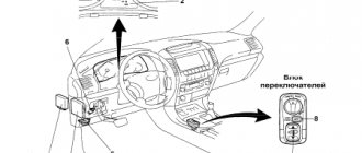
Location of fuses and relays in the cabin.
The fuses in the cabin are located behind the plastic cover of the instrument panel, and the relays are located on the back of this mounting block.
Fuse location diagram.
Explanation:
| F1 | (15A) Rear window wiper/washer |
| F2 | (10A) Ignition system, air conditioning/heater control, air conditioning compressor clutch solenoid |
| F3 | (10A) Cigarette lighter fuse Toyota Prado 120 |
| F4 | (20A) Differential lock control unit |
| F5 | (10A) Power supply for auxiliary ignition circuits |
| F6 | (7.5A) Accessory power connector relay (front/rear), multifunction control unit |
| F7 | (20A) Air suspension control unit |
| F8 | (15A) Rear window wiper/washer |
| F9 | (10A) Fog lights, trailer connector, tail lights |
| F10 | (30A) Windshield cleaner/washer, headlight cleaner/washer |
| F11 | (10A) Seat belt indicator, reverse light switch, immobilizer, vehicle speed sensor, refrigerator |
| F12 | (10A) Multi-function control unit |
| F13 | Engine management system (some models) |
| F14 | (15A) Cigarette lighter, accessory power connector |
| F15 | (20A) Anti-pinch safety switch (right rear door glass) |
| F16 | (7.5A) Instrument cluster control unit |
| F17 | (30A) Right seat electric drive |
| F18 | (20A) Pinch safety switch (left rear door glass) |
| F19 | (10A) SRS system |
| F20 | (30A) Left seat electric drive |
| F21 | (20A) Anti-pinch safety switch (left front door glass) |
| F22 | (10A) Motor control |
| F23 | — |
| F24 | (7.5A) Engine management system (some models) |
| F25 | (30A) Multifunction control unit |
Relay location diagram on the interior mounting block.
Explanation:
| 1 | Horn relay |
| 2 | Rear light relay |
| 3 | Multifunction control unit relay |
| 4 | Accessory power connector relay (front/rear) |
Location of fuses and relays in the engine compartment mounting block.
Main fuse block.
Explanation:
| 1 | Main ignition circuit relay |
| 2 | Starter relay |
| 3 | Fog light relay |
| 4 | Accessory power connector relay |
| 5 | A/C Condenser Fan Motor Relay |
| 6 | Rear window defroster relay |
| 7 | Air conditioning compressor magnetic clutch relay |
| 8 | A/C/Heater Fan Motor Relay |
| 9 | ABS relay |
| 10 | ABS pump relay |
| 11 | ESP (Stability Control) Relay |
| 12 | Fuel pump relay 1 |
| 13 | Mass Air Flow Sensor (MAF) Relay - (1GR-FE) |
| 14 | Engine control relay |
| 15 | Fuel pump relay 2 (petrol engine) |
| 16 | Hill Descent Control (HDC) Relay |
| 17 | Headlight relay |
| F1 | (7.5A) Diagnostic connector (DLC) |
| F2 | (7.5A) Intake air heater heating element, heater control unit |
| F3 | (15A) Fog lights |
| F4 | — |
| F5 | (10A) Brake lights, hill descent control (H DC), engine management system, electronic transmission control unit (TCM) |
| F6 | (10A) Heated rear view mirrors |
| F7 | (30A) Rear air conditioning/heating control panel |
| F8 | (20A) Air conditioner condenser fan motor |
| F9 | (40A) Intake air heater heating element 3 |
| F10 | (40A) Intake air heater heating element 2 |
| F11 | (50A) Fuse/Relay Box, Instrument Panel 1 - Fuses F14/F15/F17/F18/F20/F21/F25, Starter Relay |
| F12 | (40A) Intake air heater heating element 1 |
| F13 | (50A) Fuse/relay box, instrument panel 1 - fuses P1-P8/P10/P11/F24 |
| F14 | (50A) Active suspension system compressor |
| F15 | (50A) Air conditioner/heater fan motor |
| F16 | — |
| F17 | (140A) Generator (with intake air heater) |
| F18 | — |
| F19 | (7.5A) Heater/Air Conditioner Fan Motor Resistor |
| F20 | (30A) Rear window defroster |
| F21 | (10A) Air suspension control unit |
| F22 | (20A) Fuel heater |
| F23 | (20A) Seat heater |
| F24 | (10A) Low beam lamp (right) |
| F25 | (10A) Low beam lamp (left) |
| F26 | (10A) High beam lamp (right) |
| F27 | (10A) High beam lamp (left) |
| F28 | Engine management system (08/05^) |
| F29 | (10A) Anti-theft/central locking control unit |
| F30 | (10A) Multi-function control unit |
| F31 | (20A) Audio system, navigation system, audio amplifier |
| F32 | (10A) Instrument cluster control unit |
| F33 | (80A) Glow plugs |
| F34 | (30A) Navigation system |
| F35 | (30A) Trailer electrical connector |
| F36 | (25A) Anti-theft/central locking control unit, anti-theft/central locking signal control unit |
| F37 | (20A) Anti-pinch safety switch (right front door glass) |
| F38 | (20A) Engine control system (except 08/06^ 1KD-FTV) |
| F39 | (10A) Cruise control control unit, engine management system, electronic transmission control unit (TCM) |
| F40 | (15A) Turn signals/hazard warning lights, trailer presence indicator |
| F41 | (15A) Air flow sensor (MAF) (1GR-FE) |
| F42 | (10A) Horn, anti-theft/central locking control unit |
| F43 | — |
| F44 | (7.5A) Generator voltage regulator |
| F45 | Jumper - fuses F29-F32 |
| F46 | (50A) ABS solenoid valves (with ESP) |
| F47 | (30A) Fuse/Relay Box, Instrument Panel 1 - Fuses F16/F19/F22 |
| F48 | (40A) Stability Program (ESP) |
Prado 120 with 1GR-FE engine
The starter on vehicles with an automatic transmission is activated via the starter relay ( STA Relay ) which is controlled by the engine control unit. Power supply to the STA Relay is supplied from the ST2 of the ignition switch. The signal from the ST1 terminal of the ignition switch through the STA (!) fuse is supplied to the engine control unit and, if there is a negative signal from the automatic transmission position selector ( Neutral Start SW ), the engine control unit turns on the starter. In cars with manual transmission, Neutral Start SW , so the signal from terminal ST1 of the ignition switch is supplied to the starter relay.
Prado 120 with 1KD-FTV diesel engine D4D and 1KZ
The diagram for switching on the starter on diesel versions of the Toyota Prado 120. The principle is the same as on the 2TR.
starter 2.7kW
starter 3kW
starter 2,2kW
applicability of starters on diesel Toyota Prado 120
D4D Prado 120 starter repair