Home › Land Cruiser ›
Land Cruiser 100 fuses are located in blocks and protect the vehicle’s electrical network from breakdowns, including short circuits, damage to the braid, and exposure to increased electrical load.
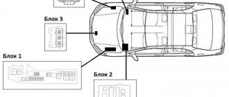
The following are the names, approximate locations of various fuses and components of Land Cruiser 100 of different years of production, including left-hand drive and right-hand drive.
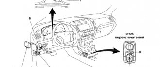
Fuses and blocks in the Land Cruiser 100 interior
Fuse diagram in the cabin for the LHD layout from 1998 to 2003.
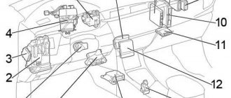
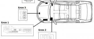
The fuses in the Toyota Land Cruiser 100, produced from 1998 to 2003 , for the left-hand layout ( LHD ) are located on the left (when viewed from the side of the car interior). Next to the diagram is:
- fusible links for steering column settings, turn signal relays - №1, №4;
- key transponder (controlling computer) - №5;
- unit that controls door locking and ETC - No. 6, No. 7 ;
- block that turns on/off the headlights - №1;
- AHC or relay design designed to control body height - No. 22 ;
- main airbag unit (located almost in the center of the cabin) - №21;
- control block - №19;
- deceleration sensor - №20;
- control units of the dashboard and anti-theft system (located above, in the center) - №10, №11.
On the right side of the left-hand Land Cruiser 100 there are the following: an auto antenna relay ( No. 12 ), a gearbox control unit that controls the engine ( No. 13 ).
Below are the control units for differential locking ( No. 14 , No. 15 ), cruise control ( No. 16 ), distribution block ( No. 17 ), and control unit for the auxiliary heater ( No. 18 ).
In contrast to the specified configuration, in the Toyota Land Cruiser LHD produced in 2003-2007 , the key auto transponder computer fuses ( No. 5 ) are located on the right, and instead of the distribution block or MTR relay (on the right), a safety block ( No. 17 ) is installed.
Interior fuse diagram for LHD layout from 2003 to 2007
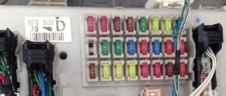
Fuse block in the cabin TLC 100 (1998 – 2002)
The fuse box diagram in the cabin
of the Kruzak 100 has fuses (fuse blocks) in the cabin that turn off if necessary:
- electric mirrors Land Cruiser 100 ( MIRR ) - No. 1 ;
- airbags, seat belt pretensioning ( SRS ) - No. 2 ;
- ABS, injection mechanism, other pillows/belts, signal indicating discharge ( IGN ) - No. 4 ;
- cigarette lighters, car antenna, audio system ( CIGAR ) - No. 3 ;
- rear window heating ( DEFOG ) - No. 15 ;
- power windows, lock, sunroof, steering wheel position changes, ABS, seat drive ( POWER, ECU-IG ) - No. 5, No. 21 ;
- STOP signals ;
- lighting ( DOME ) - No. 6 ;
- structure for monitoring body position ( AHC-IG, AHC-B ) - No. 7, No. 18 ;
- differential lock control circuit ( DIFF ) - No. 8 ;
- service warning indicators, gearbox, rear lights, ( GAUGE ) - No. 9 ;
- washers, windshield wiper ( WIPER ) - No. 10 ;
- device for idling the engine ( I/UP ) - No. 11 ;
- rear heater ( RR HTR ) - No. 20 ;
- front fog lights ( FR FOG ) - No. 12 ;
- rear air conditioner ( RR AC ) - No. 14 ;
- anti-theft system, steering wheel adjustment, daytime running lights ( ECU-B ) - No. 16 ;
- license plate lighting, side lights, running lights, panel lighting ( TAIL ) - No. 17 ;
- diagnostic connector ( OBD ) - No. 19 ;
- outlet ( PWR OUTLET ) - No. 22 .
Fuse assemblies LC 100 (2002 – 2007)
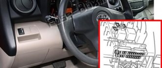
Diagram of the left fuse box in the cabin
The left fuse block of the Land Cruiser 100 includes a shutdown control:
- cigarette lighter ( CIG ) - No. 2 ;
- air conditioner ( A/C ) - No. 16 ;
- gasoline injection circuits ( AM1, ECU−IG1 ) - No. 4, No. 12 ;
- heated rear window, fuel ( DEFOG, FUEL HTR ) - No. 5, No. 7 ;
- additional heater ( POWER HTR ) - No. 8 ;
- reducing toxicity ( EFI NO.2, ECD NO.2 ) - No. 10 ;
- compilation of several devices ( GAUGE1 ) - No. 11 ;
- sockets ( PWR OUTLET ) - No. 1 ;
- navigator ( ECU-B1 ) - No. 13 ;
- structures for powering the Land Cruiser 100 trailer ( BATT CHARGE ) - No. 15 ;
- lights signaling the car to stop ( STOP ) - No. 17 ;
- diagnostic connector Land Cruiser 100 ( OBD−2 ) - No. 18 ;
- idle speed ( IDEL UP ) - No. 19 ;
- seat drive left ( LH SEAT ) - No. 20 ;
- central locking, power windows ( DOOR ) - No. 21 ;
- instrument panel illumination ( ACC ) - No. 3 ;
- locking systems ( DBL LOCK ) - No. 14 ;
- hatch Land Cruiser 100 ( SUN ROOF ) - No. 22 ;
- rear auto glass wiper ( RR WIPER ) - No. 23 ;
- body position control ( AHC-B, AHC-IG ) - No. 6, No. 9 .
Blown and serviceable
Land Cruiser 100 fuse ( assembly fuses on the right ):
- charging for a caravan ( BATT CHARGE ) - No. 18 ;
- central lock, power windows ( ECU−B2 ) - No. 1 ;
- washer ( WASHER ) - No. 3 ;
- steering wheel tilt/height adjustment ( TIL&TEL ) - No. 20 ;
- interior lighting Land Cruiser 100 ( DOME ) - No. 5 ;
- steering ( VGRS ) - No. 6 ;
- left window lifters ( P/W (FL), P/W (RL) ) - No. 7, No. 8 ;
- windshield wiper ( WIPER ) - No. 9 ;
- rear air conditioner ( ECU−IG2, RR A/C ) - No. 10, No. 21 ;
- all-wheel drive diagram ( DIFF ) - No. 2 ;
- heated seats ( SEAT HTR ) - No. 11 ;
- light for automobile R-running ( GAUGE2 ) - No. 12 ;
- instrument cluster ( MET ) - No. 13 ;
- distributed injection system ( ING ) - No. 14 ;
- anti-theft ( SECURITY ) - No. 15 ;
- rear, front right window lifters ( P/W (RR) and P/W (FR) ) - No. 16, No. 17 ;
- audio system ( RADIO ) - No. 4 ;
- electric right seat ( RH SEAT ) - No. 22 .
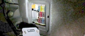
Diagram of the right fuse box in the passenger compartment
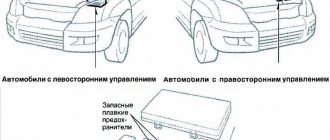
Fuse blocks under the hood TLC 100
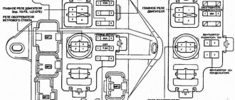
Block diagram in the engine compartment
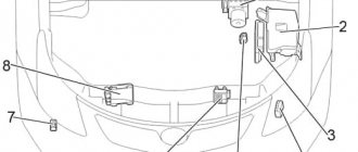
fuse diagram includes (located on the right side of the engine compartment):
- additional heating circuit - №7;
- cooling liquids - №8;
- air conditioning fan - №9;
- headlight cleaning devices - №10;
- safety blocks (including power ones) - №4, № 12;
- left headlight control unit - №6;
- spark plug relay - №3;
- winch main relay - №2;
- injector control unit ( EDU ) - No. 1 .
On the left there is a block for controlling the right car light, daytime lights ( No. 3 ), and the inlet heater relay ( No. 14 ).
Fuse link assembly (2002 – 2007)
Fuse box diagram in the engine compartment (2002 - 2007)
The Toyota Land Cruiser 100 fuse box (fuse links), located under the hood, turns off:
- gasoline injection distribution system ( ST1 or WIP−S ) - No. 5 ;
- light for a car trailer ( TOWING, TOWING TAIL ) - No. 6, No. 17 ;
- heating for mirrors ( MIR HTR ) - No. 7 ;
- charging system ( ALT−S, FR−IG ) - No. 10, No. 15 ;
- light for fog lights ( FR FOG ) - No. 12 ;
- trailer lighting, specifically brake lights ( TOWING BRK ) - No. 13 ;
- special relay: R 1 – heater ( HTR ), R 2, R 3, R 4 – ABS-system ( ABS-MTR1, ABS-MTR2, ABS-SOL ), R 5 – engine control ( EFI, ECD ), R 6 – adjustment of the body position ( AHC ), R 7, R 8 – pumps through which gasoline is supplied ( C/OPN, F/PUMP ), R 9 – starter;
- headlight washer ( HEAD CLNER ) - No. 14 ;
- instrument panel lighting ( PANEL ) - No. 16 ;
- side lights ( TAIL ) - No. 18 ;
- fuse link “ECU_B2” (BAT) - No. 19 ;
- rear heating ( RR HTR ) - No. 8;
- telephone ( TEL ) - No. 20 ;
- audio system ( AMP ) - No. 21 ;
- fuel system ( EFI NO.1, ECD NO.1, ETCS ) - No. 22, No. 24 ;
- car sound signal ( HORN ) - No. 25 ;
- low beam, high beam ( HEAD (RH−LWR), HEAD (LH−LWR), HEAD (RH−UPR), HEAD (LH−UPR) - No. 27, No. 28, No. 29, No. 30 ;
- IGN- ( AM2 ) - No. 23 ;
- hazard warning lights, turning lights ( HAZ−TRN ) - No. 9 ;
- ABS-ku ( ABS NO.2, ABS NO.1 ) - No. 31, No. 32 ;
- AHC-special system that controls the location of the body ( AHC ) - No. 33 ;
- start ( STARTER ) - No. 34 ;
- fuse links “BAT”, “AMP”, “HAZ-TRN”, “ALT-S” ( SHORT PIN A, SHORT PIN B ) - No. 35, No. 36 ;
- engine preheating ( GLOW ) - No. 37 .
Engine compartment
The Land Cruiser 100 fuse diagram located in the engine compartment includes:
- headlight control units (behind the headlights on the right and left, respectively);
- intake heater relay (middle of the engine compartment, closer to the left side);
- glow plugs (for diesel) (extreme right side of the engine compartment, flush with the intake heater relay);
- mounting block (under glow plugs);
- winch electric drive relay (slightly to the left of the mounting block, above the fuse links);
- fuse links (under the winch electric drive relay, to the left of the mounting block);
- headlight washer relay (to the right of the right headlight control unit).
On the Land Cruiser 100 mounting block there are also relays for the fuel pump, side lights, suspension adjustment and others. Their function is to open and close an electrical circuit.
In the engine compartment there is a mounting block with an impressive list of Land Cruiser 100 fuses:
- pump for gasoline or diesel;
- heated seats;
- stoves;
- fuel heater;
- headlight cleaner;
- motor control systems;
- sound signal;
- throttle control;
- alarm;
- direction indicators;
- central lock;
- window lift drive;
- rear window cleaner and defroster;
- fog lights;
- air conditioner;
- high and low beam;
- generator
If any of the car's electrical systems does not work, first check the condition of the fuses. Perhaps there was a short circuit, and now that the natural protection against malfunctions has been destroyed, the car refuses to start the process.
So, if the fuel pump fuse of a Land Cruiser 100 breaks, the engine will not start: the car does not pump fuel into the highway, and without “blood”, which can be considered gasoline, the heart-motor will not beat.
How to check a fuse in a car
Half of car electrical faults are related to fuses. Their number in the car can be more than a hundred.
The driver must know the types of car fuses, their purpose, methods of checking functionality, replacement methods and determining the rating.
Purpose
Automotive fuses (aka fuse links) in electrical circuits are used for:
- protection against overloads of electrical circuits, fire in case of short circuit;
- protection of electronic components of the car in case of malfunction of electrical equipment and wiring;
- monitoring maximum currents in vehicle circuits;
- a kind of diagnostics of faulty electrical equipment of the car.
The last function refers to the fact that if any electronic device in the car malfunctions, the blowing of the fuse serving this unit will indicate problems in the unit.
Types and Types of Automotive Fuses
Automotive fuses are classified according to the material of the fusible insert into:
- lead;
- tin;
- alloy (tin + lead);
- aluminum.
Their important characteristic is the response time. The faster the insert melts, the more reliably the circuit will be protected during a short circuit against overheating of the conductors and possible ignition.
For this purpose, inserts are made of metals and alloys with a lower melting point (transition from solid to liquid state of aggregation). Some types use spring loading to speed up operation (FJ types).
The car uses fuses of various sizes.
The types of fuses that are most widely used in vehicle systems are:
- MAXI FX – power fuses in the engine compartment;
- FTX NORM – fuses in the engine compartment and cabin blocks;
- FNL VINI - in the engine compartment and interior fuse blocks;
- FJ10 - in the underhood power fuse block.
Depending on the fuse rating, usually indicated on its body, additional color marking is used, more precisely, the main color of its body.
Why do fuses melt in a car?
Let's look at why fuses burn in a car - the most common typical reasons.
Cigarette lighter
The cigarette lighter fuse often fails. In most cases, it is not related to smoking. The cigarette lighter often contains power connectors for additional equipment (radar detectors, navigators, other auto gadgets), a compressor, chargers for mobile equipment, splitters and tees of dubious quality.
In some cases, simultaneous connection of several gadgets can lead to exceeding the maximum current in the power circuit of the cigarette lighter connector.
There are car owners who artificially increase the fuse rating in the power circuit of the cigarette lighter connector. Doing this is extremely dangerous! The cross-section of the conductor leading to the connector may not be suitable for the increased current, it may overheat, causing a short circuit and fire.
Such situations often arise when using an advertised additional electric interior heater powered from the cigarette lighter connector.
Washer
The failure of this fuse is associated with possible freezing of water in the tank and washer system pipes at negative and slightly positive temperatures.
The mobility of the electric pump drive is impaired, as a result of which the current increases and the fuse blows.
To prevent such situations, it is necessary to promptly replace the water with non-freezing liquid and clean the entire system of water.
Dvornikov
It fails if the wipers freeze to the glass or the gearbox jams. Therefore, before starting to drive in the morning in the cold season, it is necessary to check the brushes for freezing to the glass.
Heated glass and mirrors
It may burn out due to a short circuit in the electrical wiring. The weakest wiring points are in the corrugated hoses of the front doors, the trunk door, and under the driver's sill trim.
Stoves
A fuse rated at 30 Amps is usually responsible for the stove. If the heater electric motor wears out, especially the bearings and bushings, the current in the electric drive circuit increases significantly. Timely maintenance of the stove fan helps to avoid such situations.
Lighting systems
They often burn out if the power is set, non-standard lamps are installed, especially xenon lamps with an ignition unit, the current consumption of which is much higher. When increasing the rating, you should simultaneously “strengthen” the electrical wiring of the lamps by laying wires of a larger cross-section.
Engine cooling systems
They fail when the radiator fan current consumption increases for the following reasons:
- foreign objects entering the area of rotation of the fan blades;
- wear of fan motors;
- production of engine lubrication.
Engine control unit
Their burnout leads to failure to start the engine. For this reason, the driver must know where the fuses serving the engine control unit are located. Almost half of all malfunctions associated with failure to start engines are determined by their burnout.
Electric power steering
Electric power steering systems are increasingly being used in automobiles. The electric drive of the electric amplifier consumes a large current; under increased loads, the fuses often fail.
Electric parking brakes
Electric parking brakes on some car models (for example, VW PASSAT B6) are a headache for many car owners. The electric parking brakes are located in an “uncomfortable” place near the wheels.
This contributes to mechanical destruction of the housing, moisture and dirt getting inside, as a result, jamming of the engine, and blown fuses along the power circuits.
ABS systems
As a result of pump wear, the current increases and the ABS fuse blows. This leads to the inoperability of the anti-lock brake system, which is especially necessary when the road surface is in poor condition.
Central locking, power windows
The central locking drives and power windows often jam, resulting in blown fuses. Also problematic is the short circuit of the wiring in the corrugated hose of the door wiring.
How to check the fuse for serviceability
The serviceability of the fuse must be checked by removing it from the socket. An initial check can be done at the installation site, but if there is the slightest suspicion of a malfunction, be sure to remove it.
Video - how to check the fuse in a car:
Before checking the fuse with a multimeter, it should be removed from the socket. The test itself is carried out in the position of measuring the resistance at the lowest limit, or the buzzer. The resistance of a working fuse should be zero.
You can also check it visually. The working element is usually visible through a special window, a transparent housing, or protrudes from the housing. Such a test is often deceiving, since there are microcracks in the current-carrying zone that are not visible to the naked eye.
Original ODB2 scanner Scan Tool Pro Black Edition
Once connected you will be able to:
- Read error codes and erase them from the ECU.
- Keep a log of your trips and fuel consumption.
- Display in real time:
- engine speed;
- vehicle speed;
- oil pressure;
- coolant temperature;
- readings from all available sensors;
- and much more!
The scanner is compatible with devices based on iOS, Android, Windows
Electrical connection diagrams - general information
Failure of any electrical circuit components requires checking:
- battery charge;
- reliable contact in wiring terminals;
- protective elements.
The color of the wire corresponds to the marking:
- ВLK – black wire.
- BLU - blue.
- BRN – brown wire.
- GRY - gray.
- GRN – green wire.
- LT – all light colors.
- NCA - undefined.
- ORG - orange.
- PNK – pink wire.
- PPL – purple wires.
- RED – red.
- TAN – golden.
- VIO – purple wires.
- WHT – white wire.
- YEL – yellow wire.
Possible designations for connecting sections of an electrical circuit:
- AT - automatic transmission.
- D/V – switch.
- C/V – climate control equipment.
- K/L – light control sensor.
- PR-L – protective elements (PR).
- E/M – electromagnetic valve.
- DLC – diagnostic connector.
- DRL – running, daylight lamps.
- ECM – electrical module.
- ECU – on-board computer.
- EGR – exhaust return and purification elements.
- EVAP - elements of evaporating fuel.
- IAT – air thermometer.
- IGN – ignition circuit.
- IND – light control sensor.
- J/B – distribution block.
- J/C – electrical connectors.
- R/B – distributor of protective elements.
- VSS – speedometer.
- VSV – high voltage switching device.
Transmission:
- FLOOR A/T – floor arrangement of the transmission gate.
- COLUMN A/T – location of the rocker on the steering column.
- NORM – standard transmission mode.
- PWR – transmission speed mode.
Ignition system control:
- OFF – shutdown.
- LOCK – steering lock.
- ACC – parking mode.
- ON – switching on.
- START – start.
Thermostat adjustment:
- RESUME/ACCEL – reverse/speed.
- SET/COAST – installation/movement in neutral.
- CANCEL – cancels all settings.
Stove ventilation system:
- OFF – shutdown.
- LO – low speed mode.
- M1 – mode 1.
- M2 – mode 2.
- HI – high speed mode.
ECU connections:
- AC – climate control equipment.
- BATT – power supply.
- +B – connection with a positive rating.
- EGR – exhaust circulation.
- GND is a negative value connection.
- HT – lambda probe heating.
- KNK - detonation.
- OIL – DDM.
- OX – lambda probe.
- SL – electro-valve.
- SP – speedometer.
- STA – starter.
- TAC – speed meter.
When servicing the battery, you should not allow the terminals to be placed incorrectly, as the electrical devices of the car may fail.
Fuse box under the hood: where it is located, explanation
The Hyundai Accent has two fuse blocks. One is located inside the car, the second is under the hood.
Fuse box in the engine compartment
The fuse box is marked with an arrow.
The unit is located next to the battery and is closed with latches. There are no problems with opening. Here are a couple more photos.
Tweezers for removing fuses.
Decoding
Explanation under the picture in the table.
- 3-13 fuse links
- 14-23 relay
- F1-F13 fuses
- A - tweezers
- Circuit breakers
- F1 (10 A) - ECM-1 - Electronic engine control unit F2 (10 A) - A/CON-1 - Air conditioning compressor magnetic clutch circuit F3 (10 A) - HORN - Horn circuit F4 (10 A) - TAIL LH — Side light bulbs in the left front headlight and left rear light F5 (10 A) — TAIL RH — Side light bulbs in the right front headlight and right rear light F6 (10 A) — H/LP LH — High and low beam lamp in the left headlight F7 (10 A) - H/LR RH - High and low beam lamp in the right headlight F8 (15 A) - Front FOG - Front fog lights F9 (10 A) - ROOM LP - Interior lighting F10 (10 A) - AUDIO — Radio F11 (15 A) — ECM-2 — Idle speed control and camshaft position sensor F12 (10 A) — ECM-3 — Electronic engine control unit F13 (10 A) — A/CON-2 — Air conditioning system
- Relay 1 — Contact connector of the relay for constant low beam 2 — Fuel pump 14 — Heater fan 15 — Relay No. 2 of the air conditioning condenser fan 16 — Contact connector of the relay of the front fog lights 17 — Engine cooling fan 18 — Relay No. 1 of the air conditioning condenser fan 19 — Air conditioning compressor clutch 20 — Sound signal 21 — Starter 22 — Generator field winding resistor 23 — Side light in the rear lights
- Fuse links 3 - COND FAN (20 A) Air conditioning condenser fan 4 - P/WDW (30 A) Power windows 5 - ABS (30 A) Electronic control 6 - ABS (30 A) Electronic control unit circuit 7 - BLOWER (30 A ) Heater fan 8 - ALT (100 A) Generator 9 - BATTERY (50 A) Electric door lock, hazard warning lights, brake lights, heated rear window, horn, interior lamps 10 - LAMP (30 A) Headlights and parking lamps light 11 - ECM (20 A) Electronic engine control unit 12 - ING (30 A) Ignition coils, engine starting circuit 13 - RAD FAN (20 A) Engine cooling fan
Brakes
Brake pads, Drum pads, Pad wear sensor, Pad repair kit, Pad spacer, Rear pads, Handbrake pads, Front pads, Brake linings, Brake discs, Rear brake discs, Front brake discs, Brake drum, Rear brake drum, Drum bearing, Brake hoses, Brake pipes, Brake caliper, Caliper repair kit, Rear caliper, Caliper guides, Front caliper, Caliper piston, Caliper boot, Caliper bracket, Hydraulic accumulator, Vacuum brake booster, ABS, ABS unit, ABS sensor, Vacuum pump, Brake pedal, Switch Brake Light, Air Brakes, Parking Brake, Handbrake Cable, Brake Cylinder, Master Cylinder, Brake Reservoir, Brake Service Cylinder, Rear Brake Cylinder, Front Brake Cylinder, Brake Cylinder Repair Kit
VAZ 217 fuse box: diagram, functions, purpose
Before you start talking about VAZ 2107 electrical circuits and fuses, you need to firmly learn the following rules:
- When carrying out any auto electrical repairs, you need to reset the “minus” from the battery so as not to accidentally close the circuits of the conductive paths on the printed circuit board of the mounting block. For the same reason, it is better not to use a metal screwdriver;
- the scheme does not tolerate primitiveness. You cannot install homemade products instead of fuses, bugs, etc. Such homemade devices may have critical power dissipation with the release of large amounts of heat, since no calculations have been carried out. This may cause a fire;
- If you see that the fuses you install are burning one after another, then find out the reason before an even bigger problem happens, such as a fire in the engine compartment or a generator breakdown, for example. It is possible that you changed the location of the pins, or mixed up the current strength. The schematic diagram will help you figure it out.
Why do you need a mounting block?
All electrical circuits that supply certain consumers on the VAZ 2107, namely: headlights and direction indicators, brake lights, cigarette lighter, electric heater fan, sound signal, radiator cooling fan and many others need protection.
This is done using fuses, which are capable of passing a current of specified values. Upon reaching a certain parameter of its limit, the fuse burns out, but, “sacrificing itself,” saves the entire circuit from breakdown.
The mounting block, or relay and fuse panel, is designed specifically for convenient maintenance of all electrical circuits; it is located on the right (in the direction of travel) under the hood of the car. In addition, individual relays (electromechanical switches) are for the most part also placed in it, with rare exceptions (turning relays, for example). Their location is separate, under the torpedo.
Order and name of relays and fuses in the VAZ 2107 mounting block
On older cars, there was an old-style block, and fuses with a porcelain core and a conductor strip were used; the wider the strip, the greater the current flow. They did not differ in color, and were of a cylindrical type, located in one safety row. The top of the block is covered with a decorative dust and waterproof panel.
- On newer cars, a new type of mounting block is installed, with pin fuses, which are marked by color - red ones are designed for a current of up to 10 A, yellow ones are designed for twice as much, up to 20 A.
- Let us consider in order all the relays and all circuits protected by fuses.
- In the VAZ 2107 mounting block, three cubic elevations are visible. These are relays, or electromechanical switches:
- R1 – rear window heating relay, its fuse F5;
- R2 – high beam, its fuses are F12 for the right and F13 for the left headlights, respectively;
- R3 – low beam headlight relay, fuses F16 and F17, respectively;
If there is no light in two headlights at once (no matter whether low or high) and replacing the fuses did not help, it is better to change the relay. If this does not help, the lamps may need to be changed or there is a problem in the wiring.
There are free “seats” for relays:
- Headlight washer with cleaner – the most “bourgeois” option;
- Sound signal.
- Turning on the “Carlson” - radiator cooling fan.
Special mention should be made about the last two places: jumpers are installed there to “close directly” the circuits without a relay. It must be remembered that if the jumper is not installed tightly and there is an open circuit, then the cooling system fan may fail.
If, after all, the engine overheats, then you urgently need to turn on the heater at full power, with maximum temperature and double airflow, and, if possible, gain a good speed on the highway.
The set includes a standard place for tweezers, which are convenient for changing fuses:
Below is a diagram of the location of the circuits relative to the fuse numbers. They are coded as follows (the second column is the maximum current strength, A). A schematic diagram of electrical equipment can help those with better visual memory understand it.
| F1 | 10 | Heater, white reversing lights, signal, heated rear window; |
| F2 | 10 | Windshield wiper motor, headlights, pumps for washing both headlights and windshield; |
| F3, F4 | 10 | Spares |
| F5 | 20 | Heated rear window and relay |
| F6 | 10 | Console elements: cigarette lighter and clock |
| F7 | 20 | Sound relay and "Carlson". Advice: do not honk frequently or loudly when the cooling radiator is on. |
| F8 | 10 | Hazard warning lights, turn signals |
| F9 | 7,5 | Rear fog lights |
| F10 | 10 | Many functions: instrument panel – brake lamps, battery lamps, “choke”, electric fan, generator excitation winding, electro-pneumatic valve. |
| F11 | 10 | Brake lights, interior lighting |
| F12 | 7,5 | Right high beam |
| F13 | 10 | Left high beam |
| F14 | 10 | Left dimensions, room lighting, engine compartment lamp |
| F15 | 20 | Right dimensions, clock, glove compartment, cigarette lighter |
| F16 | 10 | Right low beam, headlight washer and cleaner |
| F17 | 7,5 | Left low beam |
