Yesterday I asked during the drive what kind of airbag the error B1801 was getting and the kind people gave the answer that the error was in the driver’s airbag, which is in the steering wheel.
Today I decided to replace my Chinese cable with an old original one, with broken tracks and non-working buttons on the right side of the steering wheel. Any non-working buttons are better than a non-working pillow.
I decided to change it without disconnecting the battery, because... in theory nothing should happen. I took off the pillow (I already described how to remove the pillow and change the cable earlier), started the car, connected to Techstream, and got the second error “B1811”. To be sure, I unfastened the seat cushion (I had turned off the car beforehand) and caught another error indicating that it was the driver’s seat cushion. This means it’s definitely the steering wheel cushion and this is not related to the installation of heated seats (more on that later).
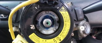
Well, in general, I removed the Chinese cable, installed the original one, connected everything, started the car - the pot-bellied guy disappeared. So it's definitely a train. Well, then I decided to get confused with transferring contacts. I found information on the Prius forum that the yellow wire is responsible for the buttons that don’t work for me (if you look at the wiring harness that comes from the buttons) and it needs to be transferred to the next socket, where the track should be alive (there are “empty” wires in the connector itself). » holes where you can connect).
I started calling the tester what went where and how, poking the original cable and the Chinese one. It turned out that on my original cable, 2 tracks were broken, the yellow wire is connected to one, and the second, which should be “free”, immediately to the left of the yellow one. I found only one live, unused track in the socket where the cruise control is plugged into. I had to move the yellow wire there. On the wiring harness from the car, the socket can be easily disassembled with a small screwdriver and the wires can be moved there wherever and however you want without effort.
I also noticed that the colors of the wires at the “input” and “output” of this cable did not match. In fact, the yellow wire from the buttons corresponds to the red wire in the wiring harness from the car. Anyway. I swapped the wires in the connectors, connected everything, started the car: the airbag error disappeared, the buttons work, the cruise turns on (but I haven’t checked it while driving). Through techstream I erased all the errors that I created, there are no new ones. I'll watch what happens next.
Yes, it’s a little collective farm, but this is not a solution. But now there is no free $100 for an original snail, and driving with a non-working airbag is somehow not a good idea.
After assembly, I decided to ring the Chinese cable - no matter how I twisted it, all the tracks are alive. The scribe is kind of shorter. Either a contact has come loose somewhere in the connector, or something has oxidized, but if you believe the tester, then everything should work. I left it as a spare for now, don’t throw it away...
It took about two hours of leisurely work with coffee breaks to disassemble, reassemble, dial and reconnect the wires in the chips.
Description of error B1801 Toyota
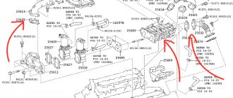
The steering column circuit consists of the SRS central unit, the steering volute and the steering wheel. Toyota error code B1801 is recorded in the control unit if an open circuit is detected in the steering cable circuit. In the description of the error for a Toyota car, the cause is a malfunction of the driver's airbag squib, but as a rule, the cause of the error is a broken steering cable. First of all, you need to check the cable and find out what is causing it - replace it.
A cable break most often occurs when removing the steering wheel or when replacing (repairing) the steering column intermediate driveshaft.
Precautions for servicing SRS “AIR BAG” and “SEAT BELT PRE-TENSIONER”
- Never check electrical connectors on airbags, side air curtain modules or seat belts.
- Never disassemble or tamper with seat belt pretensioners, adaptive load limiters, seat belt pretensioners, or tamper with the electrical connectors of these items.
- Do not use equipment to test SRS circuits unless recommended in the Vehicle Service Manual. Equipment may vary for each model.
- Before servicing the SRS, turn the ignition off, disconnect both battery terminals, and wait at least 3 minutes. For approximately 3 minutes after removing the terminals, the airbag and seat belt pretensioners may still be active. Therefore, do not work on any SRS connectors or wires until at least 3 minutes have passed.
Failure to follow these recommendations may result in accidental activation of these modules, increasing the risk of serious injury or death.
The AirBag light is on, I bought a Techstream cable, connected it, errors:
The spiral cable is 100% intact, the pillow itself is intact, what else can I check?
What does error code c1735 mean on Prado and how to fix it
Error c1735 in Toyota Prado concerns the compressor equipment complex. A compressor or supercharger is designed to suck in more air and increase the power of the main power unit - the motor.
The mechanisms of the SUV are connected to each other by electrical circuits. A break or short circuit leads to loss of communication between the elements. The integrity of the wires is compromised as a result of rotting due to the ingress of dirt, sand and dust.
The fault code indicates a loss of electrical voltage in the exhaust valve circuit located on the compressor. Sometimes the problem lies in the valve.
The owner of an SUV is quite capable of fixing the breakdown. If the wires are short-circuited, they are replaced, and if they are broken, the integrity is restored. Repair shop specialists will carefully examine the condition of the units and issue a verdict, on the basis of which they will repair the machine.
Read also: Wheel key for car
Table with errors
Full description of error codes for Toyota cars:
General faults
The following components are subject to diagnosis:
- all sensors installed on wheels;
- anti-slip system control unit;
- wires from the ABS control module to the controllers and control unit;
- contacts on the regulators.
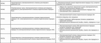
Transmission faults
- malfunction of the speed shift sensor;
- gear drive failure;
- damage to the cable or one of the contacts on it;
- software malfunction of the control unit or use of an old version of software (software);
- lack of communication between the engine and gearbox control modules.
Possible causes of the malfunction:
- selection mechanism stroke sensor;
- incorrect operation of the selector drive unit and speed switch assembly (system electric motor);
- automatic transmission module malfunction;
- damage or wear to the shift joint or fork rod.
- malfunction of the drive device for selecting and switching speeds in the assembly;
- short circuit in the transmission electric motor line;
- problems in the operation of the TCM module.
More details on what to check:
- Screen filters for the solenoid valve of the variable valve timing drive. These elements can be clogged or torn, and sometimes they are not installed correctly.
- Leakage of motor fluid at the seating surfaces of the gas distribution valve drive unit seals.
- Interruption of the supply of engine fluid to the solenoid valve of the drive mechanism.
- Integrity of the timing belt for wear.
Possible causes of the problem:
- incorrect compression in the engine cylinders;
- air leak;
- damage to the cylinder head gasket or head;
- faulty or clogged mass air flow sensor;
- failure of the lambda probe or damage to one of the contacts on the devices;
- fuel filter clogged;
- injector malfunction.
- failure or incorrect functioning of the electric pneumatic valve for controlling the turbocharger;
- break or short circuit on the vacuum control line;
- malfunction of the turbocharger device;
- breakdown of the recirculation system valve;
- damage to vacuum pipes or leakage;
- malfunction of the power unit control unit.
- malfunction of the fuel filter device;
- leakage or loosening of the fuel line clamps (you need to check the integrity of the nut for tightening the fuel pump cover and housing);
- breakdown of the fuel pump device.
Possible causes of the malfunction:
- battery discharge or damage;
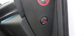
- malfunction of the ignition switch or Start/Stop system;
- regular use of low-quality fuel;
- problems with the immobilizer;
- malfunction of the anti-theft system;
- critical engine failure;
- clogged one of the filters that affects startup;
- faulty injectors or oxygen sensors.
Sensor malfunctions
To resolve the issue, it is recommended to do the following:
- Check the integrity of the connectors on the block connecting the sensor to the dashboard. Perhaps the contact has come loose and needs to be reconnected.
- Diagnose the integrity of the cable through which the sensor is connected to the instrument cluster.
- Check the quality of the connection between the controller and the transmission unit.
- Carry out diagnostics of contacts for short circuits.
- malfunction of the boost pressure controller, sensor parameters are not within the range of normalized values;
- problems in the functioning of the turbocharger control drive unit.
- damage to the sensor power wiring or the bulbs installed in the brake lights;
- failure of the relay or safety device of the optical elements;
- damage to the fuse socket or contacts;
- malfunction of the sensor installed on the brake pedal;
- problems with the control unit.
- malfunction of the left or right front engine speed controller;
- damage to the wiring supplying the regulator;
- malfunction of the rotor speed mechanism;
- errors made when installing the sensor;
- Malfunction of the brake actuator control module assembly (ABS).
Electrical and electronic faults
Possible causes of the malfunction:
- the heating element has failed;
- the lambda probe fuse is blown;
- the wiring supplying the sensor is damaged, or a short circuit has occurred in the electrical circuit;
- the contact on the controller power supply has oxidized;
- The ECM motor control unit has failed or is not working correctly.
- stopping the engine when idling;
- difficulty starting the engine;
- “triple” of the power unit when driving uphill;
- RPM surges.
Possible causes of the malfunction:
- battery discharge;
- damage to the battery, which led to leakage of electrolyte and its inoperability;
- oxidation of the battery terminals or damage to the clamps;
- generator device malfunction;
- failure of the regulator relay;
- Damage or breakage of the drive belt.
Possible causes of the problem:
- failure of the clutch release actuator device;
- the smoothness of the fork or release bearing is impaired;
- failure of the clutch basket;
- use of non-original spare parts to repair the system;
- errors made when installing parts;
- using a control unit with outdated software.
- line damage or short circuit on the reverse light switch wire;
- failure of the switching mechanism travel controller;
- breakdown of the travel sensor of the selection mechanism;
- a malfunction of the TCM module or a software failure in its operation;
- Reverse light switch is broken.
- the control unit has not calibrated the zero position of the deceleration controller;
- the vehicle position was not stabilized during calibration;
- the SRS control module is faulty or operates intermittently;
- the control unit has failed or is not functioning correctly.
- broken or damaged line of the speed shift solenoid valve SR;
- SLU is shorted or disconnected.
damage to the wires on the instrument cluster or disconnection of contacts;
malfunction of the main wiring harness in the engine compartment;
failure of the left front anti-skid sensor;
Possible causes of the problem:
damage or wear of the harness with electrical circuits connected to the instrument cluster;
malfunction of the twisted wire assembly;
failure or disconnection of the contact from the horn button;
- the anti-skid system control module detects an impulse of a break or damage to the power line of the rear left squib;
- breakdown of the airbag knock sensor;
- failure of the control module or software failure of the SRS device.
- short circuit in the power supply wiring of the driver's knee airbag knock sensor;
- failure of the device's squib;
- breakdown or software malfunction in the operation of the SRS control module.
- Communication error between the engine control module and the ID code block. A detailed diagnosis of the wiring harness is required.
- Communication line failure. It is recommended to diagnose the ECM module.
- Identification element differences detected during the exchange of information between the identifier module and the ECM. It is necessary to check the operation of the modules.
To diagnose, you need to do the following:
- Check the battery. The cause of the problem may be its discharge, which causes the generator to work in increased mode, which leads to an increase in voltage. You need to make sure that there is no damage to the battery case, as well as the integrity of the contact clamps.
- Perform diagnostics on the generator drive belt. If the product is worn out, it must be replaced.
- Check the operation of the generator device. The cause of the problem may be a faulty regulator relay.
To find the cause, perform the following steps:
- the sensor itself is checked - the contact may have come off the device;
- diagnostics of the electrical circuit connected to the sensor is performed;
- The parking radar control unit is diagnosed.
Two-digit Type 9 codes
Possible causes of the malfunction:
- damage to the pins on the connection block;
- cable break or wear of the insulating layer;
- malfunction of the EFI unit itself;
- software problem;
- Battery malfunction.
- candles;
- coils;
- high-voltage wires;
- distributor.
Fault codes are considered for the following Toyota models:
- 4Runner
- Avensis T25 (Avensis T25);
- Avalon (Avalon);
- Auris (Auris);
- Aristo (Aristo);
- Brevis (Brevis);
- Caldina (Kaldina);
- Carina (Karina);
- Cami (Kami);
- Camry V40 (Camry);
- Chaser (Chaser);
- Corolla MMT, Ceres, SV40 (Corolla);
- Corona Premio (Crown Premio);
- Crown 1G FE (Crown);
- Estima (Estima);
- Fielder;
- Isis (Isis);
- Ipsum (Ipsum);
- Gracia (Grace);
- Granvia (Granvia);
- Highlander (Highlander);
- Hilux (Hilux);
- Land Cruiser 200 (Land Cruiser);
- Majesta (Majesta);
- Mark, Mark2 (Mark);
- Nadia (Nadia);
- Noax (Noah);
- Passo (Passo);
- Platz
- Prado (Prado);
- Previa (Previa);
- Prius (Prius);
- Rav4 (Rav 4);
- Soarer (Sorer);
- Surf
- Town;
- Verso (Verso);
- Vista (Vista);
- Vitz (Vitz);
- Wish (Wish);
- Yaris (Yaris);
- Windom (Windom);
What needs to be done to make error c1726 disappear
To eliminate an error, the cause of its occurrence is first identified. The fault code based on the results of computer diagnostics indicates a problem in the operation of the air suspension device. This unit ensures the vehicle's cross-country ability in normal and extreme conditions.
The principle is to adjust the body lift. At the same time, the pneumatic system prevents damage to parts of the lower part of the vehicle and ensures ease of operation.
The malfunction consists of wear or damage to the air cylinders. When the engine is not running, the vehicle lowers its ride height. The service life of the units is exhausted due to the ingress of dirt, dust and sand.
It’s easy to check the condition of the air springs: when you start the engine, the car instantly increases its ground clearance. Otherwise, the air cylinders are inspected.
The devices cannot be repaired but require replacement. The cost of spare parts and labor reaches 100 thousand rubles. After this, the scanner will stop giving error c1726 in Toyota Prado 120.
How to diagnose the error?
The self-diagnosis process for Toyota vehicles can only be performed using connectors DLC1 and DLC2.
The test block is made in the form of a small plastic module equipped with a lid. Depending on the car model, the location of the connector may vary, but usually it is located in the engine compartment on the left side. On the block cover there is the inscription “Diagnostic”. In older versions of Toyota, the device is located next to the battery.
For Toyota Karina cars 1992-1997, as well as Corona and Mark 1992, error codes can only be read by reading the blinking LEDs. In newer versions of vehicles, the DLC2 module is located in the vehicle interior. It can be seen under the center console panel or near the driver’s feet, under the steering wheel. The module is made in the form of an oval or circle. The diagnostic process consists of closing certain contact elements of the block, which must be connected in a specific sequence.
Algorithm for checking:
- The protective plastic cover is removed from the connector. On the reverse side of the lining there is a special diagram showing the terminals of the block.
- Using a piece of wire, cable or paper clip, you need to make a jumper that is mounted between the pins numbered TE1 and E1.
- The key is inserted into the lock and the ignition is activated. When conducting diagnostics, the heating and air conditioning systems must be turned off.
- During the test, you need to look at the Check Engine LED indicators (for diagnosing the power unit) and at O/D (for the gearbox). The user must record the number of blinks of the light bulb, as well as the intervals.
Pin designation on the DLC diagnostic block
You can determine the absence of malfunctions in the operation of the internal combustion engine (ICE) and gearbox by two symptoms:
- LED lights blinked evenly at the same interval and duration 11 times;
- The Check indicator blinks continuously and evenly at intervals of 4.5 seconds.
If there is no contact diagram on the cover or it has been erased, you can determine the required pins as follows:
- The car's ignition system turns on.
- One of the contact elements of the light indicator is connected to any standard engine ground bolt.
- The second output of the light bulb is connected in turn to each contact of the diagnostic block.
- At the moment when the Check indicator lights up on the dashboard, we can conclude that the required pin has been found.
To read the code you need to count the LED blinks:
- when a combination appears, the LED blinks quickly, lights up for a few tenths of one second;
- the time interval between decimal and unit readings will be no more than 1.5 s;
- the pause between each subsequent code will be 2.5 seconds;
- series of codes for various problems are separated by a pause of 4.5 s.
Video: Toyota car self-diagnosis
The JDM27 channel in its video showed the process of diagnosing the engine and automatic transmission of a Toyota car.
Self-diagnosis
Self-diagnosis allows the car owner to independently detect and correct the breakdown. Of course, if the motorist has the necessary knowledge to conduct a vehicle inspection. If you have never encountered the need for self-diagnosis, then our website will help you figure it out and correctly carry out the work to check your Toyota.
Toyota cars are equipped with two connectors for self-diagnosis. They are called "DLC 1" and "DLC 2" and stand for "Data Link Connector". “DLC 1” is visually a rectangular plastic box, which in most models is located under the hood on the left side. You can identify the first self-diagnosis connector by the inscription “Diagnostic” on the connector cover.
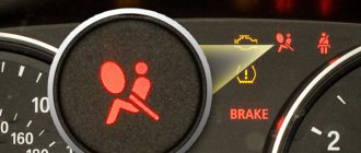
If the control unit has detected any errors in the operation of the engine, the driver will know about this by a lit lamp on the panel.
As for the faulty operation of the automatic transmission, the driver will learn about breakdowns in the operation of the unit through the illuminated “O\D” lamp. Accordingly, to identify malfunctions in the ABS, SRS and TRC systems, there are also corresponding lamps on the instrument panel.
The second connector for self-diagnosis in almost all Toyota models is located on the driver's side under the dashboard. It has a slightly different configuration, since using this connector, special additional equipment for diagnostics is connected to the transport. It is worth noting that this connector, although located in an inconvenient place, allows you to check the car while driving.
If you are the owner of an older Toyota model, then you need to look for the diagnostic connector in the engine compartment. These connectors are round in shape and marked in yellow and are located near the battery. In this case, there are simply no connectors located in the car interior.
To independently check a Toyota, you can use two types of fault combinations. The first is called type 09. The combination is a two-digit code with certain characteristics:
As for the second type of fault combinations, it is called type 10. It is a single-digit code, where the number of pulses corresponds to the fault combination. Its characteristics are:
Step-by-step diagnostics
To carry out self-diagnosis of the internal combustion engine or transmission system, do the following:
Advice: if you are not sure that you have made the correct contacts, then do the following. Turn on the ignition and take a test lamp with wires, connect one of them to ground, that is, to the Toyota body, and connect the other wire in turn to each connector for self-diagnosis. When you find “TE1”, the Check Engine light will start blinking. Of course, this operation should be performed with an assistant, since it will not be particularly convenient for you to diagnose the connectors under the hood and at the same time monitor the dashboard.
This instruction is relevant for all Toyota cars. This completes the self-diagnosis. Now you only need to decipher the received error codes, which we will discuss further.
How to reset the error?
To clear a fault code, perform the following steps:
- The car's ignition system turns on.
- On the diagnostic block, to reset the memory of the control unit, contacts TC and E1 are closed.
- Over the next three seconds, the user must press the brake pedal at least 8 times.
- Then you need to make sure that the LED indicator blinks with a pause of 0.5 seconds.
- The ignition is turned off and the jumper is disconnected from the pins. If the error codes are successfully cleared, the anti-lock brake indicator will not illuminate on the instrument panel.
You can use a computer to remove combinations of faults. If the diagnostics were performed using a laptop, software is used to reset the memory.
Decoding combinations
Gasoline internal combustion engines
First, let's look at deciphering the combinations of self-diagnosis faults inherent to Toyota gasoline engines.
| Fault error codes and their interpretation in Russian for Toyota Corolla Fielder Runx Allex from 2000-2006 | |
| Combination | Decoding |
| 12, 14 | The control unit informs the car owner about the incorrect operation of the crankshaft position control sensor. |
| 14,15 | A breakdown of one of the four ignition coils has been reported. |
| 16 | Incorrect operation of the transmission has been registered. It is recommended to carry out a more thorough check of the gearbox. |
| 19 | Incorrect accelerator pedal position. It could also be a problem with the pedal position sensor. |
| 21 | The oxygen sensor has failed. For correct operation, it is recommended to replace the device. |
| 22 | The refrigerant temperature control device in the refrigeration system sends an incorrect signal to the BC. The sensor needs to be replaced. |
| 24 | The intake air temperature control sensor is broken. |
| 25 | The oxygen sensor sends an incorrect signal to the on-board computer. In particular, the BC recorded a signal that the mixture in the injection system was too lean. |
| 31 | The control unit reports incorrect operation of the absolute pressure control device in the internal combustion engine system. |
| 34 | Malfunctions in the functioning of the turbocharging system have been reported. |
| 36 | The CPS sensor has failed. |
| 41 | The on-board computer reports an incorrect signal coming from the throttle position control device. |
| 42 | The driver is notified of a breakdown of the vehicle speed sensor. |
| 43 | The on-board computer receives an incorrect signal from the starter. A thorough check of the mechanism should be carried out. |
| 49 | Incorrect operation of the fuel pressure monitoring device. It is necessary to replace the sensor and check again. |
| 52, 53, 55 | Incorrect operation of one of the knock sensors. The device should be replaced. |
| 92 | Incorrect operation of the cold start injector. The element must be replaced. |
| 98 | A breakdown of the vacuum control device in the vacuum brake booster was registered. |
Diesel internal combustion engines
Next, let's look at deciphering the errors that occur when diagnosing Toyota cars with diesel engines.
| Combination | Decoding |
| 12 | A broken crankshaft sensor has been reported. |
| 13 | The control unit has detected a breakdown in the operation of the shaft speed control device. |
| 14 | A breakdown in the operation of the injection timing adjustment valve was detected. |
| 15 | Indicates that the throttle servo is not operating properly. |
| 17 | There are problems with the control unit. It is necessary to make a more accurate diagnosis of the block. |
| 18 | Problems have been detected in the operation of the electromagnetic bypass valve. The device should be replaced and diagnostics performed again. |
| 19 | The clutch pedal position control device does not work correctly. Replace the sensor. |
| 22 | The antifreeze temperature control mechanism in the cooling system has failed. |
| 24 | The intake air temperature sensor has failed. |
| 32 | The on-board computer registered a malfunction in the functioning of the correction resistors. |
| 35 | Malfunction of the boost pressure control device. Replace the sensor and re-diagnose the vehicle. |
| 39 | Incorrect operation of the fuel temperature sensor. |
| 42 | The vehicle speed sensor has stopped working. The device must be replaced. |
| 96 | There is a malfunction in the EGR valve position sensor. |
Automatic transmission
| Combination | Decoding |
| 11 | This combination means that no malfunctions have been identified in the operation of the automatic transmission system. |
| 37 | A malfunction of the unit input shaft speed control device has been reported. |
| 38 | Indicates a failure of the transmission fluid temperature sensor. To prevent damage to the unit, you should replace the sensor, and then do the diagnostics again. |
| 42, 44 | There has been a malfunction in the output shaft speed sensor. It is recommended to replace the device for correct operation of the unit. |
| 46 | The hydraulic accumulator pressure control solenoid has failed. |
| 61 | There is a malfunction in the speed sensor. The device should be replaced. |
| 62, 63 | The first or second solenoid has failed. |
| 64 | The control unit informs the car owner about the incorrect operation of the torque converter lock-up clutch solenoid. |
| 73 | The on-board computer detected incorrect operation of the center differential lock clutch solenoid. |
Other codes
Next, let's look at the error codes that appear when diagnosing a Toyota using special equipment. The list of errors is far from complete, but the most common malfunctions are considered.
| Combination | Decoding |
| c1201 | This combination indicates that the motor is not operating correctly. in practice, such an error occurs if the engine speed drops below 500. |
| p0171 | The combination indicates that the fuel mixture level in the engine is too lean. |
| p1604 | The car's on-board computer reports a breakdown of the intake system. A detailed check of the system should be carried out. |
| p1656 | An open or short circuit has been reported in the VVT system. Also, the on-board computer could record a breakdown in the operation of the VVT valve or electronic control unit. |
| b1801 | This code indicates an open circuit in the squib circuit on the driver's seat side. The wiring should be checked for shorts and breaks. |
| p1349 | Indicates incorrect operation of the VVT-i valve. The device must be replaced. |
| c1241 | The on-board computer reports that the pressure limit switch in the ABS unit is closed. The circuit should be checked for breaks and short circuits. |
| p0352 | Malfunctions were detected in the operation of the ignition system circuit. To ensure proper operation of the transport, check the circuit more accurately. |
| p0051 | The oxygen sensor heating device has failed. |
| b0101 | The control unit reports incorrect operation of the security system, in particular the airbags. |
The cost of diagnosing errors for Ford at service stations in Moscow and St. Petersburg
Approximate prices for computer diagnostics of faults:
| City | Company name | Address | Phone number | Price |
| Moscow | North Motors | St. Dubninskaya, 83 | +7 | 2500 rub. |
| Silver elephant | St. Pyalovskaya, 7 | +7 | 3500 rub. | |
| Saint Petersburg | Automagic | St. Uchitelskaya, 23 | +7 | 2000 rub. |
| ClinliCar | Bolshoy Sampsonievsky Ave., 61k2 | +7 | 3000 rub. |
Error code c1727: problem and solution
The malfunction consists of a failure of the rear right air suspension cylinder. The owner will receive such a decryption after computer diagnostics. In reality, it often happens that the tank is fully operational, but the problem lies in a violation of the integrity of the wires. Equipment connectors become clogged and electrical signal transmission is interrupted.
Read also: New law on transport tax 2021 how much
Before visiting the workshop, an inspection of the internal parts of the car is carried out. Surface dents and holes indicate damage to the air spring. Air is removed from the reservoir, causing the suspension to not work at full strength.
Damage also affects connecting elements – wires and connectors. In frequent cases, they contain a problem that produces error c1727 in Toyota Prado.
To eliminate the malfunction, restore the tightness of the wires and clean the connectors. The code stops being displayed.
However, if the reservoir in the rear of the vehicle breaks down, the part must be replaced.
More category errors
B1802/51B1803/51B1805/52B1806/52B1807/52B1808/52B1810/53B1811/53B1812/53B1813/53B1815/54B1816/54B1817/54B1818/54B1820/55B182 1/55B1822/55B1823/55B1825/56B1826/56B1827/56B1828/56B1830/57B1831/57B1832/ 57B1833/57B1835/58B1836/58B1837/58B1838/58B1840/59B1841/59B1842/59B1843/59B1845/61B1846/61B1847/61B1848/61B1850/62B1851/62B 1852/62B1853/62B1855/63B1856/63B1857/63B1858/63B1860/64B1861/64B1862/64B1863/ 64B1865/65B1866/65B1867/65B1868/65B1900/73B1901/73B1902/73B1903/73B1905/74B1906/74B1907/74B1908/74B1920/77B1921/77B1922/77B 1923/77B1925/78B1926/78B1927/78B1928/78B2796/99B2797/99B2798/99C0226C0236C0246C0256C0273C0274C0278C0279C0371C1201C1203C1210C1 225C1232C1241C1243C1245C1271C1272C1279C1300C1336C1361C1381C1401C1402C1403See all errors →
Toyota car diagnostics
Diagnostics are available on cars of the entire Toyota model range and are divided into two types:
Before starting electronic diagnostics, the driver must ensure that all systems and main mechanisms of the Toyota vehicle are in working order. To do this, you should check the fuses, electrical wiring, and also examine the connections and components of the vehicle for damage.
If any serious problem is detected, it must be eliminated, and only then carry out computer diagnostics, which can happen:
Step-by-step self-diagnosis
Type 9 error codes common to all Toyota vehicles are represented by two-digit codes.
| Fault error codes and their interpretation in Russian for Toyota Corolla Fielder Runx Allex from 2000-2006 | |
| Code | Decoding |
| 11 | No power to EFI unit |
| 12 | No signal from the engine speed sensor |
| 13 | No signal from the engine speed sensor at speeds above 1000 rpm |
| 14 | There is no signal from the minus ignition coil or from the minus coil number one (if there are two of them) |
| 15 | There is no signal from the minus of ignition coil number two |
| 16 | There is no connection between the automatic transmission control unit and the engine control unit |
| 17 | Incorrect signal from camshaft position sensor number 1 |
| 18 | Incorrect signal from camshaft position sensor number 2 |
| 21 | Incorrect signal from the oxygen sensor, if the engine is V-shaped, then the heater of the left main oxygen sensor is faulty |
| 22 | Incorrect signal from engine temperature sensor (THW) |
| 23 | Incorrect signal from the intake air temperature (THA) sensor |
| 24 | Incorrect signal from the intake air temperature (THA) sensor |
| 25 | Mixture too lean |
| 26 | Mixture too rich |
| 27 | Incorrect signal from the additional oxygen sensor (left for V-engines) |
| 28 | Incorrect signal from the oxygen sensor (on V-engines, the heater of the right main oxygen sensor) |
| 29 | The additional oxygen sensor is faulty (right for V-engines) |
| 31 | Incorrect signal from the air flow sensor or, if there is none, from the pressure sensor in the intake manifold (vacuum sensor) |
| 32 | Incorrect signal from air flow sensor |
| 34 | Boost faulty |
| 35 | Incorrect signal from the atmospheric pressure sensor in the intake manifold (vacuum sensor) |
| 38 | Automatic transmission fluid temperature sensor |
| 41 | Incorrect signal from throttle position sensor (TPS) |
| 42 | Incorrect signal from the vehicle speed sensor (speedometer) |
| 43 | No starter signal (STA) to engine control unit |
| 46 | Solenoid valve number 4 or its circuits are faulty |
| 47 | The auxiliary throttle position sensor (TPS) or its circuit is faulty |
| 48 | The auxiliary air supply control system is faulty |
| 51 | No idle signal from TPS |
| 52 | Incorrect signal from the knock sensor (if there are two of them, then from the left or from the front) |
| 53 | Problems in knock sensor control circuits (ignition timing) |
| 55 | Incorrect signal from the knock sensor (if there are two of them, then from the right or from the rear) |
| 61 | The main speed sensor or its circuit is faulty |
| 62 | Solenoid valve number 1 or its circuits are faulty |
| 63 | Solenoid valve number 2 or its circuits are faulty |
| 64 | Solenoid valve number 3 or its circuits are faulty |
| 65 | Solenoid valve number 4 or its circuits are faulty |
| 67 | The O/D switch or its circuit is faulty |
| 71 | EGR control system faulty |
| 72 | Fuel cut solenoid |
| 77 | The pressure control solenoid or its circuit is faulty (in the machine) |
| 78 | There is no signal to the fuel pump or its circuits are faulty |
| 81 | The circuit between TCM and ECT1 is faulty |
| 82 | The circuit between TCM and ESA1 is faulty |
| 84 | The circuit between TCM and ESA2 is faulty |
| 85 | The circuit between TCM and ESA3 is faulty |
| 86 | Engine speed sensor is faulty |
| 88 | The circuit from the engine control unit to the automatic transmission control unit is faulty |
| 89 | Communication between the engine control unit and the TRC system control unit is broken |
| 99 | No fault codes |
The general list of unambiguous codes (type 10) for a Toyota car consists of the following items.
| Code | Decoding |
| 1 | No breakdowns |
| 2 | The air flow sensor gives an incorrect signal |
| 3 | Incorrect signal from the communicator |
| 4 | The coolant temperature is outside the normal range, the sensor has failed |
| 5 | Incorrect communication with the oxygen sensor |
| 6 | The fault lies in the number of engine revolutions |
| 7 | Throttle valve in incorrect position |
| 8 | The sensor shows incorrect intake air temperature |
| 9 | Car speed problem |
| 10 | There is no starter signal |
| 11 | The air conditioner is broken or the toggle switch responsible for the neutral position in the car is faulty |
From english:
Decoding the error B1801/51 from Toyota: Engine Coolant Temperature Circuit Malfunction
Make:
Toyota
Code:
B1801 51
Definition:
Engine Coolant Temperature Circuit Malfunction
Description:
Monitor runs whenever the following DTCs are not present: None Engine coolant temperature sensor voltage: Less than 0.14 V,or more than 4.91 V
Cause:
- Open or short in ECT sensor circuit
- ECT sensor
- ECM
Failure Type:
Not Programmed
This sub type is used by the control module to indicate that programming is required.