The 3S-FE valve clearances and their correct alignment directly affect the service life of the vehicle’s power plant components. Departure from the recommended standards occurs through natural wear of parts and increased loads on the vehicle engine, however, this phenomenon is typical only for intake ones. In the case of exhaust valves, due to the constant exposure to exhaust gases, the valve seat burns out and the part shifts. As a result, the thermal gap is reduced relative to the established norm. If the problem is left unattended for a long time, the situation will only worsen, adjustment will become impossible - replacement can solve the problem.
If the 3S-FE timing belt breaks, the valve should not bend.
Valve adjustment on 3S-FE
Valve adjustment on 3S-FE
bering » 18 Nov 2012, 17:11
Hello to all fellow Kaldin breeders! My name is Victor, I'm here recently. I want to share my experience of adjusting valves after rebuilding my engine. I had to sort through it a month after the purchase, and thoughts about capital appeared even when I just drove Kaldina from Novosibirsk. For 1250 km. I ate and spat out 3 liters of oil through the dipstick. Well, while I was driving around, I ordered spare parts, took out potatoes and cabbage from the dacha, and then topped it up with exactly a liter every 500 km. When accelerating, the engine created a light smoke screen with an unpleasant odor, although it drove quite cheerfully and consumed 12 liters of gasoline as expected. On the highway from Novosib to Tyumen I generally consumed 90 liters per 1250 km. In short, after opening it (I disassembled the engine for a week, but only removed the head, the block turned out to be in good condition, the ellipse did not exceed 0.03 mm), it turned out that the oil scraper rings were severely worn, the compression rings were stuck, and the MSCs were dead. The head was washed from carbon deposits, the seats were severely corroded, we had to scrape them, and this significantly lifted the valves. But I don’t know how much I decided not to cut down the stems (as many people recommended). After assembly, I picked up new adjusting washers, for this I first installed the camshafts, stretched them, wrote down which washers were worth, measured the gaps and put everything in a table. Next, I calculated which washers were needed to provide the required clearances. We managed to adjust the intake valves with old washers, but for the exhaust valves we had to buy 6 new ones at a price of 180-220 rubles per piece! And then it turned out that two valves remained clamped. Apparently I didn’t take something into account or measured it wrong. Under one cam the gap is approximately 0.23 mm and under the other 0.18, with the norm for exhaust valves being 0.28-0.38 mm. I read that with this arrangement the valves make poor contact with the seat and overheat due to the fact that they cannot transfer heat to the head and burn out. While I was getting ready to solve the problem, I drove 600 km. At first, 0.5 liters of oil was consumed, then the consumption stopped. Even when installing and removing the camshafts, I slightly unscrewed the bolts on the camshaft covers incorrectly and one bolt pulled the thread in the head. Because of this, it then turned very tightly, I thought it would burst. But no, it worked, I just had to look for an M7x1 tap to drive the thread. And so, having chosen a free day, I put it back into my head. And now with the photos.
Added after 4 minutes 25 seconds: After removing the valve covers, take a tap and cut a thread in the problem hole.
Added after 3 minutes 8 seconds: Taking this opportunity, I threaded all the holes for the camshaft cap bolts. In half of the threaded holes there was this kind of cocoa.
Added after 12 minutes 50 seconds: Let’s take a closer look at the question of how to properly unscrew the bolts on the camshaft covers. Although this topic has been covered over and over again in the AvtoDat book on 3S engines. You need to use your straight hands to take a 24mm open-end wrench and, hooking the hexagon on the camshaft (no matter which one), turn them to such a position that one point stamped on the gear looks at another point stamped on the other gear and so that they lie on the same straight line. In this case, another point located on the exhaust shaft gear is located approximately 30 degrees in front of the first point and with further rotation of the camshafts it will meet the same point on the intake shaft. In short, you need to observe 4 points. Leave the shafts in this position. . the first cover from the timing belt and also the 4th and 5th. Then the 2nd and 3rd. Then we completely remove the 1st, 4th, 5th. Why don’t we touch the rest or turn everything at the same time? Because with this position of the marks on the gears, while unscrewing the covers, the shaft begins to lift from the belt side, it warps in bed and pulls the threads on the studs. This is how I ruined my carving. After removing the first three covers, slowly and sadly unscrew the remaining two, trying to maintain a horizontal position of the shaft. It is here, using a small 10mm head (since a large one cannot be reached), you will feel the full force of the valve springs pressing on the threads of 4 M7 bolts.
Added after 4 minutes 31 seconds: Photo from
inserted the tap incorrectly. Photo of poop in threaded holes.
Added after 6 minutes 32 seconds: After removing the camshaft, carefully move it to the side. Next is a short digression. Since I couldn’t adjust the gaps properly using washers, because... one valve already had the thinnest washer of 2.5 mm and for the other there was nothing at hand, so I decided to cut off the valve stems a little using this drill and abrasive cutters of different shapes.
Added after 7 minutes 55 seconds: Remove the cup from the valve to be processed. They come out a little tight, but you can’t help with a screwdriver; you can scratch the thinnest chrome film.
Added after 13 minutes 44 seconds: After removing the cup, a view of the valve stem opens. Next, take a caliper and measure the distance from the top of the stem to the valve holder. Why to the cracker? I haven't found another thrust plane. There are two crackers there, the distances to one and to the other were very different.
Added after 11 minutes: I measured 1.7 mm to one cracker, 2.2 mm to the other. It is clear that they differed in size, but I think this is a feature of the manufacture of the crackers themselves. The valve was holding dead, but I was driving a repaired engine! So far nothing has dried up. Next, we clamp the cutter, cover the motor with a rag with a hole in the middle, just above the valve being processed, so that the abrasive does not fly into the motor itself. Of course, a little abrasive will get on the spring and the seat of the cup, but from there the abrasive can be at least partially removed later. And don't forget about glasses!
Added after 13 minutes 3 seconds: A small nuance: The hole in the rag must be made carefully, using scissors, and try to ensure that there are no protruding threads. I had a little something wrong and when I turned on the machine, the rag got caught and wrapped around the shaft. Straightaway. We file the end of the valve, trying to do it evenly over the entire surface. We literally work for 20 seconds. Next we take measurements. Few? We continue to remove the metal. To be happy, I needed to remove 0.1 mm. I did this in 2 passes. Measurements with a barbell in different planes showed that the result seems to have been achieved. (as it turned out later, I was slightly mistaken). Next, remove the protective rag, wrap a clean cloth moistened with oil around the screwdriver and thoroughly wipe the valve plate, spring and cup pusher seat. Next I also processed the second valve.
Added after 13 minutes 39 seconds: Yes. I missed the point about cocking the exhaust shaft gear. Before removing it from the bed, you need to screw an M6 bolt 15-20 mm long into the hole located in the gear almost vertically after setting the marks. to fix the movable gear relative to the stationary one. If this is not done right away, then it will be difficult to move the moving gear to correctly install the camshaft. Although I moved. Using a screwdriver. I screwed in the short bolt first. And he didn't record anything. And the gear left.
The photo shows the discrepancy between the holes in the gears. I had to unscrew this bolt and screw in a longer one, then use a screwdriver to catch two holes while screwing in the bolt. It's still a hassle.
Added after 11 minutes 16 seconds: What are the two gears for? The spring-loaded movable gear selects the gap in the mesh of the intake and exhaust valves, thereby reducing noise during operation of the gas distribution mechanism. We put everything back together in reverse order. We wipe, grease with oil and put the glasses in place. We find the marks on the exhaust camshaft, align them with the marks on the intake camshaft and lower the shaft into place. We attach the camshaft covers in the order in which they were installed. There are arrows on the top of the covers; they should face the timing belt. The lids are also numbered, so it's difficult to confuse them. First tighten covers 2 and 3, making sure that the shaft falls horizontally without distortion. Next, we put covers 1,4 and 5 and tighten them so that covers 2 and 3 are loosened. Then we tighten 2 and 3 again almost to the end. Next we tighten covers 1, 4 and 5 but not all the way. Next, pull covers 2 and 3 to the end, observing the position of the camshaft. We tighten the remaining covers and tighten them with a torque of 19 N/m or about 2 kg.
Added after 5 minutes 58 seconds: Then I took a set of screws and checked the clearances of all the exhaust shaft cams. Don't forget to remove the retaining bolt from the gear!! Because When adjusting, you need to turn the camshaft and the bolt may rest against the head housing! One thing became clear. under the cam of one valve, which I sawed, the probe passed 0.3 mm and did not pass 0.35 mm. Norm! And under the other one, a 0.2 mm screw passed through and did not pass 0.25 mm. This is not gut. But it got a little better, the gap before was 0.18 mm. It turns out that I undercut the rod by 0.05 mm. But there was no time to sort everything out again. This valve has a 2.6 mm washer. Then I’ll buy a 2.5 mm washer and change it. I hope my experience will be useful to someone, especially beginners.
Source: caldina-club.com
Valves 3S-FE
The 3S-FE valve clearances and their correct alignment directly affect the service life of the vehicle’s power plant components. Departure from the recommended standards occurs through natural wear of parts and increased loads on the vehicle engine, however, this phenomenon is typical only for intake ones. In the case of exhaust valves, due to the constant exposure to exhaust gases, the valve seat burns out and the part shifts. As a result, the thermal gap is reduced relative to the established norm. If the problem is left unattended for a long time, the situation will only worsen, adjustment will become impossible - replacement can solve the problem.
If the 3S-FE timing belt breaks, the valve should not bend.
Engine fault overview
Despite the thoughtfulness and unpretentiousness of the 3S-FE engine, drivers face some problems:
- increased fuel consumption. Occurs due to improper operation of the throttle valve or one of the sensors that transmit incorrect information to the ECU. Contaminated injectors also interfere with the formation of a normal mixture. Carbon deposits on the pistons lead to excessive fuel consumption due to changes in the volume of the combustion chamber and loss of power;
- increased appetite for butter. Often found in cars with mileage over 200,000 km. Carbon deposits on the pistons indicate severe burns through compression and oil control piston rings and leaking valve seals. The malfunction may also be in the sensors: lambda probe, intake air temperature sensor or map sensor;
- Long cold start. The problem is due to a breakdown of the fuel injectors or temperature sensor;
- Unstable engine operation, loss of power. The reason is a breakdown of the EGR valve or engine oil getting into the spark plug wells: the ignition occurs with misfires, and the engine stalls at idle;
- motor vibrations. The problem occurs when the side cushions wear out or there is a loss of pressure in one of the cylinders.
Engine problems can be corrected by replacing or cleaning the elements. The 3S-FE design allows for simple repairs even in garage conditions.
https://www.youtube.com/watch?v=KcCTjpVy-sc
Required Tools
Adjustment of 3S-FE valves is impossible without previously prepared tools. To carry out the work you will need the following tools:
- micrometer;
- tweezers with a curved tip;
- adjusting washers;
- screwdriver;
- flashlight.
a set of styli, especially those with smaller pitches are of interest;
Before starting work, remember that the car engine must be cold to accurately measure and adjust the gap.
List of car models in which it was installed
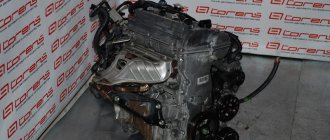
The Toyota 3S-FE engine was produced in Japan at the Kamigo Plant, and also in the USA at Toyota Motor Manufacturing, Kentucky, Inc. at Georgetown from 1986 to 2003. 3S-FE was installed on Japanese cars of class D, E, and was also installed on minivans and SUVs with front-wheel drive and all-wheel drive. In total, more than a million cars were produced for the Japanese, European and American markets.
3S-FSE motors released after 1996 were installed on a few Corona Premio ST210, as well as Vista V50 and Nadia SXN10.
| Model Toyota | Drive unit | Years of manufacture |
| Avensis ST220 | 2WD | 1997 — 2003 |
| Caldina ST190, ST210 | 2/4WD | 1992 — 2002 |
| Camry V20, V30, V40 | 2/4WD | 1986 — 1998 |
| Carina ST170, ST190, ST215 | 2/4WD | 1987 — 2001 |
| Carina ED ST200 | 4WD | 1993 — 1998 |
| Celica ST160, ST180, ST200 | 2/4WD | 1986 — 1996 |
| Corona ST170, ST190, ST210 | 2/4WD | 1987 — 2001 |
| Corona Exiv ST200 | 2WD | 1989 — 1998 |
| Curren ST200 | 2WD | 1994 — 1999 |
| Ipsum/Picnic SXM10 | 2/4WD | 1996 — 2001 |
| Gaia SXM10 | 2/4WD | 1998 — 2002 |
| Nadia SXM10 | 2/4WD | 1998 — 2002 |
| Rav4 SXA10 | 2/4WD | 1996 — 2000 |
| Vista V55, Ardeo | 4WD | 1998 — 2002 |
Similar article Technical characteristics of the 3S GE BEAMS engine
Disassembly
Disassembly is the initial stage of adjusting the 3S-FE valve clearances. The first step is to disconnect the negative battery terminal cable and high-voltage wires. Then the accelerator cable and, in the case of an automatic transmission, the throttle control cable are disconnected. Having dismantled the accelerator cable bracket, disconnect the hoses of the crankcase ventilation system. Next, you should dismantle the cylinder head cover, as well as the gasket, for which you need to unscrew the four nuts and get rid of the spark plug tubes. The seals must be placed in the exact sequence in which they are disconnected in order to prevent leakage of fuels and lubricants.
Dismantling
To remove the idle air valve on a 3S-FE, you first need to remove the air filter cover, after loosening the clamp and disconnecting the temperature sensor. Afterwards, remove the pipe leading to the throttle body, also loosening the clamp and pulling out the cable and hoses.
We release the pipe from the attached cables and hoses before removing
Remove the cable casing, loosen its fastening bolts, and then remove the coolant pipes (dismantle only when the engine is cool!) and the “vacuum” hose. Disconnect the chips from the idle speed sensor and the remote control position sensor, then unscrew the fastening bolts and nuts. Finally, we remove the idle speed sensor winding, and then the valve itself (pay attention to the gasket, try not to damage it).
Adjustment
The initial stage of adjusting the 3S-FE valves is to set the piston of the first cylinder to the TDC position of the compression stroke. It is necessary to rotate the crankshaft pulley and align the marks with the timing belt cover. Make sure that the pushers of the first cylinder are in a free position while the pushers of the fourth cylinder are tightened. If this is not the case, you should rotate the 3S-FE crankshaft 360 degrees and align the marks again.
Next, the valve clearance must be measured using a suitable feeler gauge, and the measurement results between the pushrod and the camshaft should be recorded in order to select a suitable shim.
Gap standards for 3S-FE intake: 0.19 – 0.29 mm, exhaust: 0.28 – 0.38 mm.
Then you need to rotate the crankshaft 360 degrees again and take measurements in the remaining valves, recording the results.
The adjustment process begins with dismantling the adjusting washer, for which you need to rotate the crankshaft until the camshaft working lobe is installed in the upper position. While pressing the pusher, place a special tool between the camshaft and the pusher. We remove the tool. Next, remove the adjusting washer using a small screwdriver with a magnetic tip.
Using a micrometer, we determine the size of a new suitable part. To do this, first of all, we measure the thickness of the old washer with a micrometer and, based on the notes made and established standards, determine the thickness of a suitable adjusting washer. After installing the new part, it is necessary to measure the gap in the 3S-FE valve drive again.
Formula for calculating the thickness of the required washers.
Where X is the thickness of the new washer; Y—thickness removed; Z - measured gap.
Assembly
Reassembly begins with installing the cylinder head cover. First you need to get rid of the old seal and apply sealant to the cylinder head. Then we install the cylinder head gasket and cover, as well as four spark plug tube seals. We tighten the nuts with a torque of 23 Nm.
Next, we connect the hoses of the crankcase ventilation system 3S-FE and the accelerator cable bracket. Next, we return the throttle control cable to its place if the car is equipped with an automatic transmission. Having connected the accelerator cable and high-voltage wires, we connect the battery.
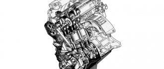
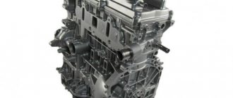
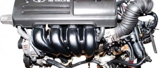
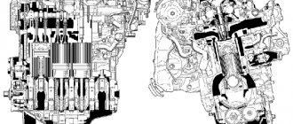
Design Features
The 3S-FE internal combustion engine is designed simply and thoughtfully. The cylinder blocks are made of cast iron, the cylinder heads are made of aluminum. There are two camshafts. There are no hydraulic compensators. The cylinder heads are poorly ventilated, so the engine is not suitable for forced loads. Fuel supply system is injection with electronic multipoint injection.
The disadvantages of the 3S-FE engine include the noisy operation of the exhaust system and noticeable rustling of the pulleys and rollers. After 200,000 km, a good oil appetite and high fuel consumption appear. The engine is piled up against the engine shield, making access for maintenance difficult.
Similar article Technical characteristics of the Mercedes OM 612 engine
A serious problem was discovered after the 1996 modernization. The designers reduced the mass of the piston group by 0.7 kg, leaving the crankshaft unchanged. To save money, the updated crank mechanism was not balanced, which led to vibration. Under its action, the bolt heads of one of the connecting rods are torn off. The part breaks loose and pierces the cylinder block. To prevent an accident during repair of the piston group, it is necessary to change the connecting rod bolts and tighten them strictly with the nominal torque.
Modifications to the unit in 1996 affected the ignition system. Mechanical distributors were replaced with dual coils that operate on 2 spark plugs. This doubled the load on the spark plugs and wiring.
Some 3S-FE models have an EGR gas recirculation system. An electric vacuum valve and a vacuum modulator-membrane are used for control. When the gas becomes rarefied, the EGR valve opens. After the EGR valve closes, the exhaust gases pass through the modulator filter. Every 2 years, it is advisable to blow out the filter with compressed air.
Improving the motor, the designers released a new version 3S-FSE. The unit was equipped with a D4 direct injection system and power was added, but overall the attempt was unsuccessful. The engine ran intermittently due to a broken fuel injection pump. Insufficient lubrication of the crankshaft and the accumulation of carbon deposits in the intake manifold forced owners to often visit the service center.