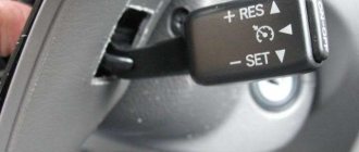
Toyota Fujitsu Ten (LEXUS) No pinout. TOYOTA CD TL1D remote control connector. all radio connectors.
Pinout of toyota car radio connectors. This scheme involves manual control of the radio, but the settings will not go wrong and the battery will not run out in a couple of days.
Search • Users • Help. Help with the pinout of the Toyota radio. In my rav 4 I wanted to replace the control unit ( ) with the one with a monitor ( ). When connecting, a problem arose - all connectors were connected.
This is what she looks like. There are three connection schemes: In general, the connector of this audio link fits very tightly into the radio - so much so that removing it without breaking off the socket is a real problem. Ceiling-mounted 7-inch monitor with DVD. Head unit DVZ-MGzt from PIONEER Toyota Land Cruiser
Help with pinout of Toyota radio
MR2 So, if you have a similar Head Unit, then everything said will most likely be relevant! Let's look at our balalaika from the back, we are interested in this connector for the changer because the purchased audio link has the same connector. Diagram Photo By the way, Toyota has 2 types of connectors for changers, and accordingly the manufacturer sells 2 different products: audiolink-big and audiolink-small. In the diagram this is a CN connector. It seems that according to the manufacturer’s idea, we should simply plug the mega-device into the connector and everything should work.
But never mind... Our connector is already occupied. A plug is already inserted into it, and if you take it out, the balalaika simply dies... it seems to glow, but does not respond to our attempts to communicate with it... I did not cut off the wiring harness from the car, but pulled it through the window: I screwed it up. And I couldn’t find any other way out... To begin with, the idea came to rearrange the pins of one connector to another, or somehow so as not to cut anything from the car.
But the design of the native Toyota connector and the connector of the mega-device are different, the contact pins there are also different, and it won’t be possible to rearrange anything back and forth. In general, the connector of this audio link fits very tightly into the radio - so much so that removing it without breaking off the socket is quite a problem. The original Toyota plug is easily inserted and removed and holds well too, but this left one is very tight! So you have to insert it all the way at the very last moment.
I decided to simply solder 2 wires to the device connector - these are pins 9 and 10 in the plug. Each one in turn had to be carefully removed, soldered the wires, and then put back in.
Now you can cut off the same Toyota plug, attach these tails to the wiring from it and everything should work, but first it’s better to check everything without cutting anything off. To make it clear, we simply parallel 2 contacts from the car’s wiring with the contacts of the mega-device. And just figure out how not to lose the warranty... And voila - it worked!
We press the Disc key on the radio - the inserted CD plays, we press Disc again - the radio seems to switch to a changer - and our device actually starts playing mp3 music with a pre-recorded SD card inserted into it!
There are some restrictions here - for example, you can’t just copy music - it won’t work - you need to create folders CD01, CD02 ... CD12 in the root - and put mp3 files inside them. It seems that there are no restrictions on file names, it seems that the bitrate is supported up to Kbps, it seems that in each folder there is no limit on the number of files, and all this seems to be the case, for example, in the instructions all this is indicated and it also states that only Transcend flash drives will work, but me and the Kingstone flash drive worked.
The maximum size of a flash drive is like 32 GB. It plays quite decently - naturally, there are no mp3 tags on the screen, only a pseudo disk number and songs - that is, the balalaika really thinks that a changer is connected. Control from the balalaika works, rewind, repeat, random song on the disc, random song on all discs, the song that was played last is remembered, the buttons on the steering wheel will also work. I don’t have them, but I know that they will. It’s not very convenient that the random song mode is turned off with any intervention - for example, when the pause button is temporarily pressed... But these are probably features of the balalaika itself.
Review of the standard car radio TC-PT120 Portal Toyota Prado 120
Car radio in Prado 120
Needless to say, car radio is not the right word - a whole multimedia/entertainment center with a powerful operating system. You can easily verify this by studying its capabilities:
- The device comes with an 8 GB SD card, and in general the radio processor can work with different cards: 4/8/16/32 GB;
- The display of the device is touch-sensitive, as required by the current reality. Drivers are gradually starting to get used to the inconvenient buttons, which require extra effort to operate.
Note. In the case of a sensor, everything is simple - just a touch of your finger is enough for this or that option to connect.
- The car radio TV tuner is digital and in DVB-T format. This is already a huge advantage, because having studied the market for similar devices, for almost the same price, we will see that most kits come with analogue tuners, while digital tuners must be purchased separately.
Note. In addition, the TV tuner comes with a powerful antenna, also designed to receive digital signals.
- The device has a built-in Sharp/Hitachi DVD receiver. The name of these brands alone speaks for itself. And there is no doubt that this receiver is capable of working continuously for 1600 days. This is real high-quality equipment with the highest impact resistance and dust/moisture resistance;
- There is a built-in 3G modem. The user will no longer need to separately purchase devices to access the Internet, like competitors. And you don’t even need to insert the SIM card into a separate unit, but just insert it directly into the radio;
- The device comes with a unique 2-year warranty. This a priori indicates a very high quality of the car radio;
- GPS navigator of a new level. Determines location accuracy and positions based on the latest data. The sensitivity of the Sirf-5 receiver (one of the best GPS receivers) is 163 dB. The kit includes an antenna, and searching for satellites occurs instantly. Along with the equipment, the user receives all the required licenses with codes and a warranty card.
Note. It wouldn’t hurt to write that the navigator plots the route itself using audio prompts.
Advantages
- The car radio also boasts excellent sound quality, thanks to the high-definition HD Audio sound card. It supports 24-bit quality, multi-channel mode (8 channels) and all formats known today. You can connect additional amplifiers and a subwoofer (see How to connect a subwoofer to a car radio: lessons for amateurs) through the connectors. Separately, you can highlight the device’s equalizer, which allows you to control all frequencies in real time. As a result, the user receives clear, not fake sound;
- The user will also receive multimedia in full. It supports digital television, plays all modern audio and video formats without any restrictions, can store 6 discs, and provides stable FM/AM radio reception. There is a unique ability for the user to edit tables and text in Microsoft Excel and Word, also without any restrictions;
- There is Bluetooth with the Hands Free profile. It allows you to connect to any modern phone model. 3G Internet works without freezes (in the access zone) and restrictions. You can use all known social resources without restrictions. The Internet access point can become not 3G, but Wi-Fi. This can also be easily used.
Note. The device is already configured with the popular navigation service Yandex traffic jams. This will be of great benefit to the driver. You will no longer have to nervously avoid traffic jams that you get into unknowingly.
- The device has connectors for connecting cameras. This can be a front or rear camera, which automatically turns on when reverse gear is engaged on the Prado. The parking system in general deserves only praise. All information from the parking sensors goes to the car radio screen (configured by connecting to the appropriate connectors on the car radio);
- You can quickly and easily connect various USB media to the car radio, again without any restrictions. Flash drives, a digital camera or an external hard drive - all of this can be easily connected. In addition, the car radio integrates with iPad, iPhone, tablets, other devices of this type, etc.
- There are slots for using SD cards;
- The device can be easily converted into an on-board computer. The car radio simply integrates with all the car's electronics. Control buttons, if necessary, are transferred to the steering wheel. Information from the necessary sensors is displayed on the screen.
Toyota Corolla 150 radio pinout
3 days with Google and a soldering iron or aux to where it is not soldered
So I got around to writing how to save myself from constant overwriting of cd-rws. On the standard radio with number 53816, the aux outputs are not soldered to the board, and there is also no button to activate this same aux. I scoured the Internet and tried a bunch of methods. None of them worked. I was already thinking about giving up and buying some kind of yator and not worrying about it, but my interest prevailed. Another couple of hours with Google and I found what I needed to get started. Some Turkish engineer did this.
This is the output of the processor responsible for activating the AUX function (To understand this, I had to find a diagram of a similar unit, which cost another couple of hours of my life). We make a jumper instead of R692 (according to the diagram there is a zero), and the process begins. When you press the disk 2 button, the AUX mode is activated.
All that remains is to find the entrance. Fortunately, at that time I already had a scheme)))
We are looking for SAF7730HV/224 on the board, under it on the other side are our treasured 3 contacts. I soldered them through 3 47nf capacitors. And the aux worked.
I hope this saves someone a couple of days of life.
PPS It is better to remove the Conder from GNG, the bass will be better.
Toyota car radio pinout
The pinout of a Toyota car radio is practically no different from the connection diagram for other car radios. The pinout for Toyota car radios is a circuit consisting of two rows of connectors. Our article will tell you how to connect Toyota devices, what you need to know for this and how to install car radios with your own hands.
rem2000 - Toyota Corona
Books and manuals Toyota Corona for free
Toyota Corona Repair and Maintenance Manual
- repair of Toyota Corona in photographs - components and assemblies of the car are described in detail - troubleshooting typical Toyota Corona faults with your own hands - color electrical diagrams
DOWNLOAD
/ download from the mirror
Toyota Corona operating manual and service manual
— operating manual — Toyota Corona service manual — troubleshooting — interactive wiring diagram
DOWNLOAD
/download from mirror
Wiring diagram Toyota Corona
— pinout of electrical connectors for Toyota Corona — features of electrical equipment — troubleshooting electrical equipment — detailed electrical diagram
DOWNLOAD
/download from mirror
Catalog of parts and assembly units Toyota Corona
— table of interchangeability of parts for Toyota Corona cars — intended for service station workers and car owners
— catalog of parts
DOWNLOAD
/download from the mirror
Toyota Corona engine repair manual
- full technical characteristics of the Toyota Corona engine - features of engine design and repair - do-it-yourself troubleshooting of the Toyota Corona engine - detailed description of the processes of disassembling, troubleshooting and assembling the engine with photographs
DOWNLOAD
/ download from the mirror
Repair manual for Toyota Corona gearboxes
— full technical characteristics of the gearbox — features of the design and repair of the gearbox — troubleshooting the gearbox and transmission of the Toyota Corona car — a detailed description of the processes of disassembling, troubleshooting and assembling the Toyota Corona gearbox with photographs
DOWNLOAD
/download from mirror
Toyota Corona injector error codes
- description and diagram of the injector - decoding of engine fault codes - troubleshooting injector faults - pinout of injector and electrical wiring
DOWNLOAD
/download from mirror
Tuning Guide
— DIY Toyota Corona tuning — engine tuning, body tuning, suspension tuning — multimedia tuning guide
DOWNLOAD
/download from mirror
Several connection schemes
Pinout of toyota car radio connectors
It is believed that the main mistake when connecting Toyota car radios is pulling the positive wire from the cigarette lighter. This will in no way have any effect, since the power of the head unit will drop several times (this is easy to verify if you pay attention to the flashing backlight while the device is operating at high volume). In addition, connecting Toyota car radios through the cigarette lighter will not eliminate sound distortion, which will begin to appear noticeably earlier. On the other hand, in some cases this option may be considered suitable for implementation. The ideal option for connecting Toyota car radios, as well as all others, is to provide the main power supply from the battery. It is advisable to use high-quality wire (it is in no case recommended to skimp on the cable) and be sure to use a fuse, which must be placed as close to the battery as possible.
Note. Let us note right away that car radios have not one, but two power wires. As a rule, yellow is responsible for the main power, red for control (goes to the lock).
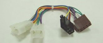
In addition, the pinout of the remaining wires:
- N* – negative wire. They are usually connected to the car body, providing ground. However, it is recommended by experts to connect it to a battery;
- C is the wire that is responsible for the amplifier or active antenna.
In addition, the car radio is also equipped with speaker wires (they go to the rear and front speakers):
- B, C-th – wires for front speakers;
- Z, F – wires for rear speakers.
Note. You also need to know that each pair of acoustic wiring contains additional monotonic and negative wires. The latter is often marked with a black stripe over the main color.
Connection according to diagram 1
Connectors for car radios
- We connect the power wires to each other;
- We connect them to the battery.
The good thing about this scheme is that it is easy to implement. On the other hand, it is only suitable for car radios with low power consumption. If you connect a powerful device according to this scheme, then in just 2-3 days in sleep mode the car radio will completely discharge the battery.
Connection diagram 2
This circuit is suitable for any powerful car radio:
- We connect the power wires to each other;
- We connect them to the battery;
- We install an additional button (it is responsible for turning the device on and off).
This scheme involves manual control of the radio, but the settings will not go wrong and the battery will not run out in a couple of days.
Connection diagram 3
Connector for car radio
Individual scheme, implying the following:
- We connect the main power wire (yellow) to 12 V;
- We connect the additional one (red) to the side lights (via a relay, the winding of which is connected to the ashtray light bulb).
Main unit
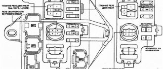
The main fuse and relay box is located under the hood of the car near the battery. The elements of this unit are responsible for the safe operation of electrical systems that provide important vehicle functions. For example, fuses regulate the flow of fuel to the pump and turn the windshield wipers on or off.
Below is a diagram of the location of fuses and relays in the block, as well as a table that shows the purpose of the main elements.
| Designation | Purpose |
| 1 | Ensuring the operation of the electronic engine control unit of a car |
| 2 | Adjusting the sound signal. |
| 3 | Ensuring the generator is operational. |
| 4 | Car interior lighting, as well as lighting for the trunk, clock, and dashboard. |
| 5,6 | Turning headlights on and off. |
| 7 | Organization of uninterrupted operation of the ignition switch. |
| Relay | |
| R1 | Fuel pump operation. |
| R2 | Starter activation relay. |
| R3 | Horn relay. |
Also, the fuses and relays of this unit are responsible for the cigarette lighter and provide electricity to the fan and the stove.
Connecting the camera according to the pinout
Knowing the pinout of the car radio, you can easily connect the rear view camera with your own hands. Using the example of the popular Toyota Ca-Fi device, we will learn how to do this. The process itself is divided into two parts: the actual installation of the device with the connection and the connection of the rear view camera.
Note. Installing and connecting the monitor is no different from installing the factory head unit. You just need to swap the connectors and that's it.
But connecting the camera can be difficult for some. Here's what you need to know:
- The rear view camera for Toyota Prado is powered by 5V;
- To connect it, you will need a connector from the factory monitor, which remains free after installing the new radio;
- This same connector is 14-pin. But we only need two video signal wires and a reverse signal;
- In addition, you will need to convert the voltage from 12V to 5V.
Note. To convert voltage means to carry out the process using a special converter, which is sold in any store.
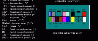
The camera connection diagram has its own pinout. This is what she looks like.
Pinout of toyota car radio connectors
The circuit is positioned as if you were looking at it from the side of the wires. The photo in the upper left corner is placed for clarity. So, in order to connect the camera to the Toyota car radio, you must first connect together the reverse signal and the Reverse wire on Ca-Fi. In addition, it will be necessary to install a converter and make a tulip for transmitting video data.
Note. This does not mean that you will have to literally do everything from scratch. You just need to buy Scotchlocks in the same store where you purchased the converter (they will help connect the wires to each other).
The photo below shows how to splice wires using tape.
Scotchlock and wires
Next we do the following:
- We start the car;
- We turn on reverse gear;
- Let's check how everything works (the monitor of the installed radio should show the image from the camera).
Thus, knowing the pinout of Toyota car radios, you can connect using any of the selected schemes. During the work process, it is extremely useful to watch a video review. Step-by-step instructions from other sources will also help. The price of installing a car radio yourself is noticeably different from the cost of specialist services, which is several times higher.
Very often, users have a question about how to connect a Toyota Corolla radio themselves and whether it is possible to do this information at all. Many people believe that connecting a Toyota Corolla radio correctly is too difficult and therefore turn to specialized centers, which brings unexpected costs.
Toyota Corolla radio
It is worth noting that Japanese cars, including Toyota 86120-60581, are crammed to the brim with electronics, which often confuses many Russians. In this case, the standard factory-type radio is replaced with a more modern one or connected quite quickly and does not require much experience in this area.
loveavto — Toyota Corona
Technical documentation for repairing Toyota Corona cars (all years of production) Free, without registration and SMS
Repair, operation and maintenance manual for Toyota Corona
- full technical specifications
- operating features
— troubleshooting Toyota Corona
— color wiring diagrams of Toyota Corona DOWNLOAD / DOWNLOAD FROM THE MIRROR
Toyota Corona Operation Manual - full technical specifications Toyota Corona - operating features
- trouble-shooting
— colored electrical circuits DOWNLOAD / DOWNLOAD FROM THE MIRROR
Toyota Corona repair manual in photographs - full technical specifications
- operating features of Toyota Corona - troubleshooting in photographs with your own hands - more than 1980 photographs of the repair process DOWNLOAD / DOWNLOAD FROM THE MIRROR
Catalog of parts and assembly units Toyota Corona - table of interchangeability of car parts
— intended for service station workers and owners of Toyota Corona cars — Toyota Corona parts catalog DOWNLOAD / DOWNLOAD FROM THE MIRROR
Detailed electrical diagram of Toyota Corona - a complete description of the electrical equipment of Toyota Corona, a detailed interactive electrical diagram of Toyota Corona - the algorithm for troubleshooting electrical equipment (starter, generator, ignition system, injection, injector) is described in detail - a detailed diagram of electrical equipment (electrical diagram) Toyota Corona - pinout of electrical connectors , pinout of electrical wiring Toyota Corona DOWNLOAD / DOWNLOAD FROM THE MIRROR
Toyota Corona engine repair manual - full technical specifications of the Toyota Corona engine - design and repair features of the Toyota Corona engine - detailed description of the processes of disassembling, troubleshooting and assembling the engine with photographs, timing belt DOWNLOAD / DOWNLOAD FROM THE MIRROR
Toyota Corona transmission repair manual
- full technical characteristics of the gearbox - design and repair features of the Toyota Corona gearbox - troubleshooting gearboxes, transmission, shafts, gears, CV joints - detailed description of the processes of disassembling, troubleshooting and assembling the gearbox with photographs DOWNLOAD / DOWNLOAD FROM THE MIRROR
but here you can earn money for a new car, and then you won’t have to repair the old one!!!
Toyota Corona
How to properly connect the factory radio of a Toyota Corolla
In order to connect the standard Toyota Corolla radio, it is worth understanding the reasons why the device is being changed.
The fact is that the proprietary Japanese version upsets many because:
- has a crooked FM range;
- reads CDs that were not purchased from company stores rather poorly;
- can shoot CDs quite far;
- The disk reading function in MP 3 mode is completely absent;
- does not accept the flash drive;
- there is a TV available, but it often does not work;
- navigation has maps of Japan or does not work at all;
- inability to repair equipment.
Connecting the Toyota Corolla radio correctly will be much easier than connecting a huge number of wires to connect the MP 3 player. However, it would be better to replace the standard radio from the Japanese manufacturer with a European version for the Toyota Corolla, which can play high-quality video and audio files.
So, connecting the radio to Toyota 86120-60581 is done in stages:
- remove the frame by unfastening the semicircular frame from the clips;
- pry it up with a screwdriver and carefully pull it out towards you;
- you can help yourself remove the knob by piercing the rear holes with a screwdriver;
- unscrew the bolts of the radio;
- disconnect all connectors one by one;
- take out the old radio.
Electrical diagrams TOYOTA CORONA - Car electrical wiring diagram
Connection diagram for rear fog lights TOYOTA CORONA
Connection diagram for rear window heater TOYOTA CORONA
TOYOTA CORONA Connection diagram for rear lights and lighting
Wiring diagram for direction indicators and hazard warning lights TOYOTA CORONA
TOYOTA CORONA wiring diagrams are above the page.
Toyota Corona model appeared in the brand's lineup in 1957. This rear-wheel drive sedan was equipped with a 0.9 engine. or 1 liter engines.
Already in 1960, production of the second “ Corona ” began, which was offered with sedan, station wagon and pickup bodies.
The third generation Toyota Corona, introduced in 1964, had sedan, hatchback, coupe, station wagon and pickup versions. This model was assembled not only in Japan, but also in Korea, Australia and New Zealand.
In 1970, production of fourth-generation cars with sedan, coupe and station wagon bodies. It was equipped with inline four-cylinder engines ranging from 1.5 to 2 liters.
The next, fifth generation of the model was produced from 1973 to 1979.
The sixth Toyota Corona debuted in 1978. The cars were produced in sedan, coupe, liftback and station wagon bodies and were equipped with engines from 1.6 to 2.4. liters
The seventh generation Corona lasted on the production line from 1982 to 1989. This model was no longer offered in the US market, replaced by the Toyota Camry.
Introduced in 1983 the eighth Corona became front-wheel drive. The car was produced in parallel with the previous generation cars. In the European market this model was called Carina II .
the ninth generation of Toyota Carina , from 1986 to 1992, was the result of a redesign of the previous model.
In 1992, the next version of the model was introduced . The European market version was called Carina E and was produced in the UK.
The latest generation cars were produced from 1996 to 2001 and were sold only on the Japanese market; in other countries this model was replaced by Avensis .
.TOYOTA electrical diagrams
How to connect AUKS to a Toyota standard radio
Often, motorists try to connect AUKS to the standard Toyota radio in order to make the most of all their capabilities. It is worth noting that the AUKS for Toyota Starlet 56037 is a connector for connecting digital media to it, including a flash drive, MP-3 player, mobile phone or tablet.
In order to connect a Toyota AUKS to the radio, you should perform a number of simple steps:
- remove the Toyota Corolla decorative panel;
- disconnect the rear window heating connector;
- remove the gearbox by disconnecting its wires and the ashtray;
- pull out the head unit;
- completely disconnect the connectors and antenna;
- disassemble the receiver housing;
- disconnect the cables;
- After that, to connect the AUKS, you need to solder the wiring to the board.
In order for the AUCS to work correctly, it is necessary to correctly pinout:
- yellow and red wires are needed for channels;
- the black wire is connected to the negative or ground;
- The following should be soldered to the board:
- RCH – red;
- LCH – yellow;
- GND – black.
AUX connection
After this, all wires should be routed through a special hole and connected to the radio. The cable is easily routed through the glove compartment, after which the receiver can be assembled and tested by connecting a phone or flash drive to the AUX cable.
Review of the installed radio in Toyota Prado 120
The standard radio installed in tlc represents an entire multimedia center on a powerful platform. Control takes place on a 6-inch touch screen with the touch of a finger. The package includes an 8 GB memory card, but the device supports SD cards of other sizes.
Digital TV-tuner with a powerful antenna that allows you to receive all types of channels. Guarantees the quality of audio and video playback. The current market offers a less modest analog option for this price.
DVD player from Japanese manufacturer Sharp/Hitachi. There is no doubt about the quality of this company's products. Allows you to connect speaker amplifiers.
For convenience, a 3G modem and USB port are built in. In comparison with car radios from other manufacturers, it is purchased separately.
The radio is complemented by the latest version of the GPS navigator, which, using an antenna, automatically connects to possible satellites and plots a route, notifying with voice messages. Contains many maps not only of Russia, but also of the world.
It is possible to transfer the control buttons to the steering wheel, with information displayed on the display.
The standard Prado car radio comes with a 2-year warranty. This is due to the high quality of the equipment.
Methods for connecting a camera to a Toyota standard radio
It is also possible to connect the camera to the standard Toyota Starlet 56037 radio in order to constantly be aware of what is happening behind you. At the same time, connecting a rear view camera to a Toyota radio will not be very difficult on your own.
To do this, the Toyota Corolla head unit must go through the pinout procedure:
- connect the wire with the yellow tulip to the rear view camera;
- place the second end of the yellow wire on the standard radio;
- connect the wire with the red tulip to the wire that will give a plus when the selector is in the R position;
- connect the red wire with the terminal that activates the short-circuit breaker to the radio wiring;
- connect the red wire to the positive permanent connector;
- Throw the black wire onto the negative ground and onto the camera.
At the same time, when connecting a rear view camera, you should connect a 12 volt wire to the purple wire of the reverse gear. But the wire that connects the camera can be combined with the one that we throw to ground.
After everything is connected correctly, it is worth debugging the cameras in the radio settings.
ELECTRICAL DIAGRAM TOYOTA COROLLA - ELECTRICAL DIAGRAM
Free, color and high-quality electrical diagrams of the Toyota Corolla in Russian. The second part is presented, containing the following components: Electric rear-view mirrors and sunroof, central locking, power windows, washers and wipers, Toyota Corolla radiator and air conditioning cooling fan and others. See the first part of the collection of Toyota Corolla electrical circuits here. To enlarge, just click on the diagram.
Electric drive of rear-view mirrors and sunroof of Toyota Corolla
Central locking - wiring diagram
Window regulators for Toyota Corolla
Electrical diagram of the ABS system (ABC)
Lighter, clock and car horn
Washers and wipers - schematic diagram
Toyota Corolla radio and stereo player
Instrument panel of a Toyota Corolla car
Radiator and air conditioning cooling fan
Diagram of the battery charging and engine starting system
CAR ELECTRONICS REPAIR
Toyota head unit connector pinout
- Standard pinout
- Pinout for low-power radios
- Pinout with connection through dimensions
The pinout of the Toyota radio complies with international requirements for car audio connection diagrams. The switching circuit uses 2, 3 or 4 plugs; the configuration of the elements depends on the model and year of manufacture of the car.
Fuses and relays Toyota Carina E (T190), 1992 - 1998
Most of the power supply circuits of the electrical equipment of the Japanese sedan and station wagon are protected by fuses.
Headlights, electric fan motors, fuel pump and other powerful current consumers are connected through a relay. The protective elements are installed in mounting blocks, which are located under the hood and in the trunk. The fuse diagrams are suitable for Toyota Carina E (T190) 6th generation 1992, 1993, 1994, 1995, 1996, 1997, 1998 vehicles with gasoline and diesel engines.
In the cabin
Component location. 1 - fuse block No. 3, 2 - fuse block No. 1.
In the engine compartment
Component location. 3 - fuse and relay block No. 2. 4 - relay block No. 5, 5 • relay and fuse block No. 7.
Standard pinout
The basic pinout of a standard Toyota radio contains the following cables:
- The gray wire is responsible for providing a positive signal when the key in the ignition control switch is turned to the ACC position.
- To ensure that equipment settings are saved, a cord with a blue-yellow or blue-white insulator is used. A positive signal is given regardless of the position of the key in the lock and the state of the security alarm.
- An additional cable with a green protective layer ensures the operation of the backlight. The cord is connected to the control of side lighting and the brightness control of the lamps.
- To supply negative power, wiring with a brown protective layer is used.
- The block design contains an additional blue cable designed to control the antenna amplifier or an electric drive for extending the antenna pin. Part of the radio has a dark blue output that allows you to control the power of an external amplifier or subwoofer.
- The front speakers are connected through the block in which the power supply cables are located. Each speaker has a negative and positive terminal; grounding the speaker coils to the body is not allowed.
- The rear speakers are located on a separate chip; the design includes a guide pin that prevents erroneous connection. The pads mounted on the car wiring are held on the body of the multimedia device using plastic clips.
Toyota Service Manuals - electrical diagrams
- Prerequisites for a field journal
- Define your corporate philosophy and start living it
- Creating lean processes throughout the enterprise
- Creating initial process stability
- Create associated process
- Establish standardized processes and procedures
- Leveling up: be more like a tortoise than a hare
- Create a culture that lets you fix problems
- Make technology compatible with people and lean processes
- Develop leaders who live your system and
- Culture from top to bottom
- Develop exceptional team members
- Developing suppliers and partners as extensions
- enterprises
- Toyota-style problem solving
- Develop Deep Understanding
- Situation and problem definition
- Complete a thorough root cause analysis
- Consider alternative solutions when reaching consensus
- Plan-Do-Check-Act
- Tell a story with an A3 report
- Lean Implementation Strategies and Tactics
Toyota Avalon service manual Free download
Toyota Avalon 2018
Toyota Chaser service manual Free download
Toyota Chaser 1988, 1989, 1990
Toyota HIACE repair manual Free download
Toyota Hiace
Toyota Echo Service manual Free download
Toyota Echo 2002
Toyota Celica Service manual Free Download
2000 Toyota Celica.