Most of the power supply circuits of the electrical equipment of the Japanese sedan are protected by fuses. Headlights, electric fan motors, fuel pump and other powerful current consumers are connected through a relay. Protective elements are installed in mounting blocks, which are located under the hood and in the passenger compartment.
The diagrams of Toyota Mark 2 models 1996, 1997, 1998, 1999, 2000, 2WD&4WD with diesel 2L-TE (2.4 l turbocharged) and gasoline 4S-FE (1.8 l), 1G-FE (2, 0 l), 1JZ-GE (2.5 l), 1JZ-GTE (2.5 l turbocharged), 2JZ-GE (3.0 l) engines.
In the cabin
The location of the block is shown in the image above. Photo is an example.
| Interior fuse box diagram | ||
| № | Current, A | Description |
| 1 | 30 | Luke |
| 2 | 10 | Front and rear lights, license plate lights |
| 3 | 15 | Air conditioning and heater control panel, fan motor, rear window defroster |
| 4 | 20 | central locking |
| 5 | 7,5 | Illumination of switches and switches, illumination of the air conditioning and heating control panel, illumination of the radio tape recorder |
| 6 | 10 | Direction indicators |
| 7 | 20 | Driver's door power window |
| 8 | 10 | Electronic engine control unit |
| 9 | 15 | ABS systems, TRC, VSC, cruise control, automatic headlights on/off |
| 10 | 20 | Brake lights |
| 11 | 7,5 | Starter |
| 12 | 15 | Instrument cluster, remote control of door locks and trunk lid, seat belt pretensioner system |
| 13 | 20 | Windshield wiper defroster |
| 14 | 20 | Electric rear left door window |
| 15 | 20 | Wiper motor |
| 16 | 15 | Fog lights |
| 17 | 20 | Power window for front passenger door |
| 18 | 10 | Radio, multifunction display |
| 19 | 10 | Air conditioning and heater, cruise control, rear fog lights, remote control system for door locks and trunk lid |
| 20 | 20 | Power window lifter for rear right door |
| 21 | 10 | Shift Lock System, Clock, Airbag System (SRS), Power Side Mirrors |
| 22 | 30 | Electric seats |
| 23 | 7,5 | Electric drive of the idle speed increase system |
| 24 | 15 | Cigarette lighter fuse mark 2 |
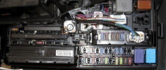
In the engine compartment
The mounting block is located near the battery and is covered with a plastic cover. General form.
I came across this information on the Internet, maybe it will be useful to someone, for me it’s a useful reminder.
The cars considered were Toyota Mark 2 in 100, 101, 105 body, Toyota Cresta, Toyota Chaser 1996, 1997, 1997, 1998, 1999, 2000, 2001. ______________________________________________________________________________________________
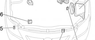
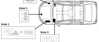
Location of components in the engine compartment.
1 - absolute pressure sensor in the intake manifold (4S-FE), 2 - absolute pressure sensor in the intake manifold (1G-FE from 08.1998), 3 - absolute pressure sensor in the intake manifold (1G-FE until 08.1998), 4 — absolute pressure sensor in the intake manifold (1JZ-GE, 2JZ-GE), 5 — boost pressure sensor (2L-TE), 6 — relay unit in the engine compartment (R/B) (2JZ-GE with VSC), 7 — relay block in the engine compartment (R/B No. 2) (except 1G-FE), 8 — fuse block, 9 — mounting block No. 2 (J/B No. 2), 10 — left front SRS sensor (from 08.1998 .) — fuel pump resistor, 12 — right front SRS sensor (since 08.1998), 13 — relay block in the engine compartment (R/B). _________________________________________________________________________________________________
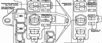
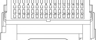
Fuse layout diagram in the engine compartment mounting block.
*1 — TOURER-V and TOURERS configurations: © — left headlight (high beam); © — left headlight (low beam);
*2 - Models with diesel engine “ECD”,
*3 — TOURER-V and TOURERS configurations,
*4 — TOURER-V, TOURERS and TOURER configurations,
*5 — GRANDE-G package,
*6 - Models with diesel engines only.
The mounting block in the engine compartment is unfolded.
Fuse and relay box in the passenger compartment. _________________________________________________________________________________________________
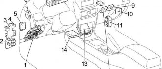
Location of interior components.
3 — mounting block No. 3 (J/B No. 3), 24 — mounting block No. 5 (J/B No. 5), 25 — light sensor (automatic headlight switching system), 26 — TEMS electronic control unit, 27 — mounting block driver's side (J/B), 28 — relay unit No. 1 (R/B No. 1), 29 — control unit (Multiplex), 30 — cruise control unit, 31 — electronic steering control unit, 32 — indicator relay brake system malfunction, 33 — ABS control unit (2JZ-GE with ABS), 34 — ABS and TRC control unit (1JZ-GTE), 35 — SRS control unit (central SRS sensor), 36 — electronic engine control unit, 37 — collision sensor (before 08.1998), 38 — deceleration sensor (ABS), 39 — automatic transmission selector lock relay, 40 — collision sensor (from 08.1998), 41 — relay block No. 4 _________________________________________________________________________________________________
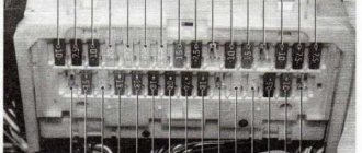
The main unit in the cabin is located at the bottom of the instrument panel.
Expanded fuse and relay box (with relay)
_________________________________________________________________________________________________ Relays located in the cabin block:
Power window relay Turn signal relay Blade defroster relay Headroom relay Fog light relay Rear window defroster relay
Toyota Mark 2 is a popular car in many regions of the Russian Federation, thanks to its reliable build quality and powerful power unit, which freely overcome Russian roads, regardless of their condition.
ATTENTION! A completely simple way to reduce fuel consumption has been found! Don't believe me? An auto mechanic with 15 years of experience also didn’t believe it until he tried it. And now he saves 35,000 rubles a year on gasoline! Read more"
However, for the stable operation of a vehicle, it is necessary to constantly maintain all its systems, in particular, monitor the quality of electrical wiring and promptly check fuses.
How to decipher fuses on a Toyota Mark 2: detailed instructions
Many home mechanics often have a lot of problems with Toyota Mark 2 fuses - the Japanese design solution is not always logical, as a result of which it takes car owners a lot of time and effort to replace damaged elements.
Meanwhile, there is a domestic marking of fuses on cars aimed at the European market, where each element has a sequential numbering.
If you have a car aimed at the Japanese domestic market, you will have to get a little confused - on the manufacturer’s official website you can find instructions for deciphering the hieroglyphs or symbols used on the main fuse block.
| Marking part number | Functional purpose of the element |
| 1 | The element is responsible for the operation of the engine radiator fan circuit |
| 2 | Fuse for the positive contact circuit responsible for charging the battery |
| 3 | A reserve element that is used to unload the circuit of other electrical systems or in case of connecting additional equipment not included in the package |
| 4 | An audio signal is connected through the element, and sometimes power is supplied to the central locking circuit and the additional alarm module |
| 5 | This fuse is responsible only for the operation of the right headlight. |
| 6 | This fuse is responsible only for the operation of the left headlight. |
| 7 | The module is necessary for overvoltage protection of the wheel traction control system |
| 8 | The part is responsible for the proper functioning of car de-icers - depending on the configuration, heating can be installed on the windshield and rear-view mirrors |
| 9 | Additional fuse for ignition switch circuit |
| 10 | The element is responsible for the uninterrupted operation of the 4WS system |
| 11 | The fuse is necessary to protect against overvoltage of the engine generator circuit |
| 12 | Additional fuse for engine radiator fan |
| 13 | The part is responsible for the operation of the anti-lock wheel module |
| 14 | Fuse protecting the direct injection system from power surges |
Note! If you purchase a vehicle with Japanese markings, it is recommended to replace all fuses with European adaptation by purchasing a special set of protective elements.
This step will significantly simplify the procedure for servicing the car in the future, especially if the driver sometimes turns to third-party mechanics for help - not every repairman will take on servicing Japanese electronics.
Fuses and relays located in the passenger compartment
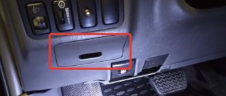
The main fuse box in the cabin (in Fig. No. 6) is located below the steering wheel, closer to the door (for models with left-hand drive). We open the panel, which is a pencil case for small items and pieces of paper. Remove it by pulling it up and towards you. Below it is the fuse box:
- TURN (7.5A) - direction indicators and hazard warning lights
- reserve
- GAUGE (10A) - lighting, dimensions, air conditioning system, reversing lights, sunroof control system, power windows, rear window defroster
- WIP (20A) - (wiper) windshield wiper and washer, and rear door glass
- I-UP/M-HTR (10A) - idle speed increase system / heated side mirrors
- ECU-IG (10A) - fuel injection system
- IGN (7.5A) - battery charging system, fuel injection system, airbag system (SRS)
- STOP (15A) - brake lights, additional brake light
- TAIL (15A) - rear lights, gauges and gauges, clock, cigarette lighter, audio system, rear window defroster, license plate light, fuel injection systems, air conditioning system, hazard warning lights, central locking
- Reserve
- Reserve
- OBD (7.5A) - OBD-2 diagnostic system
- ECU-B (7.5A) - airbag system, rear fog lights
- ST (5A) - starting system
- D/L (30A) - central locking
- FOG (15A) - fog lights
- S-HTR (15A) – (Seat Heater) heated seats
- reserve
- CIG (15A) - audio system, clock, cigarette lighter, electric side mirrors
- DEF (40A) (gray) - rear window defroster, fuse: DEF I-UP/M-HTR
- Power (30A) (pink) - electric windows, electric sunroof
The same block from the reverse side:
A — rear window defroster relay B — size relay C — integrated relay
Do-it-yourself replacement of fuses on a Toyota Mark 2: everything you need to know
The procedure for replacing faulty fuses on a Toyota Mark 2, regardless of the year of manufacture of the car or its configuration, follows an identical algorithm of actions. The entire range of work will take no more than 20 minutes of free time, and you will also need the fuses themselves, a set of Phillips and slotted screwdrivers, and a specialized puller or narrow-nose pliers.
To replace fuses on a Toyota Mark 2, you must perform the following procedure:
- To begin with, be sure to de-energize the electrical circuit in the car by disconnecting all terminals from the battery;
- Then, under the hood of the car, on the right side of the power unit, we find a small plastic box and use screwdrivers to remove the fixing fasteners. It is important to remember that the fuse box under the hood of the Toyota Mark 2 is sealed and damage to the fasteners may allow moisture or dust to enter the system, which in turn will lead to metal corrosion and loose contacts;
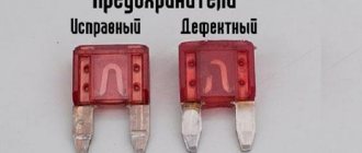
- After successfully dismantling the block cover, we conduct a visual inspection of the faulty elements. A blown fuse will have traces of melting on the body, and during dismantling it will be possible to see the destroyed part inside the product;
- Using pliers, a special puller or medical tweezers, you need to disconnect all faulty fuses and install new components. Fuses are mounted on Toyota Mark 2 by lightly pressing the part onto the connector until a characteristic click appears;
- If no faulty fuses were found, then go inside the cabin and open the second fuse box. The internal fuse box is located under a plastic cover at the bottom of the instrument panels - for free access you will have to remove the protective cover itself;
- At the end of the maintenance procedure, we connect the battery back and check all the electrical systems of the vehicle for functionality.
Note! The design of the Toyota Mark 2 electrical system sometimes causes small voltage surges when connecting or disconnecting the battery, which can damage freshly replaced fuses. In this case, the maintenance procedure will have to be repeated.
It is also recommended to pay special attention to the throughput capacity of the elements themselves - it is strictly forbidden to use fuses oriented towards higher or lower power. Using incompatible fuses or replacing fuses with protective elements and vice versa can compromise the security of the car's electrical equipment, which will lead to costly repairs in the event of a power surge or short circuit.
On the hood: Located just above the battery (or whatever it is spelled there)
Toyota Mark 2 is a popular car in many regions of the Russian Federation, thanks to its reliable build quality and powerful power unit, which freely overcome Russian roads, regardless of their condition.
However, for the stable operation of a vehicle, it is necessary to constantly maintain all its systems, in particular, monitor the quality of electrical wiring and promptly check fuses.
Land Cruiser 100 fuses: where are the blocks, decoding
Land Cruiser 100 fuses are located in blocks and protect the vehicle’s electrical network from breakdowns, including short circuits, damage to the braid, and exposure to increased electrical load.
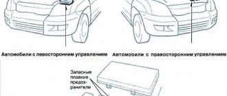
The following are the names, approximate locations of various fuses and components of Land Cruiser 100 of different years of production, including left-hand drive/right-hand drive.
Fuses and blocks in the Land Cruiser 100 interior
Interior fuse diagram for LHD layout from 1998 to 2003
The fuses in the Toyota Land Cruiser 100, produced from 1998 to 2003 , for left-hand drive layout ( LHD ) are located on the left (when viewed from the passenger compartment). Next to the diagram is:
- fusible links for steering column settings, turn signal relays - №1, №4;
- key transponder (controlling computer) - №5;
- unit that controls door locking and ETC - No. 6, No. 7 ;
- block that turns on/off the headlights - №1;
- AHC or relay design designed to control body height - No. 22 ;
- main airbag unit (located almost in the center of the cabin) - №21;
- control block - №19;
- deceleration sensor - №20;
- control units of the dashboard and anti-theft system (located above, in the center) - №10, №11.
On the right side of the left-hand Land Cruiser 100 there are the following: an auto antenna relay ( No. 12 ), a gearbox control unit that controls the engine ( No. 13 ). Below are the control units for differential locking ( No. 14 , No. 15 ), cruise control ( No. 16 ), distribution block ( No. 17 ), and control unit for the auxiliary heater ( No. 18 ).
In contrast to the specified configuration, in the Toyota Land Cruiser LHD produced in 2003-2007 , the key auto transponder computer fuses ( No. 5 ) are located on the right, and instead of the distribution block or MTR relay (on the right), a safety block ( No. 17 ) is installed.
How to decipher fuses on a Toyota Mark 2: detailed instructions
Many home mechanics often have a lot of problems with Toyota Mark 2 fuses - the Japanese design solution is not always logical, as a result of which it takes car owners a lot of time and effort to replace damaged elements.
Meanwhile, there is a domestic marking of fuses on cars aimed at the European market, where each element has a sequential numbering.
If you have a car aimed at the Japanese domestic market, you will have to get a little confused - on the manufacturer’s official website you can find instructions for deciphering the hieroglyphs or symbols used on the main fuse block.
| Marking part number | Functional purpose of the element |
| 1 | The element is responsible for the operation of the engine radiator fan circuit |
| 2 | Fuse for the positive contact circuit responsible for charging the battery |
| 3 | A reserve element that is used to unload the circuit of other electrical systems or in case of connecting additional equipment not included in the package |
| 4 | An audio signal is connected through the element, and sometimes power is supplied to the central locking circuit and the additional alarm module |
| 5 | This fuse is responsible only for the operation of the right headlight. |
| 6 | This fuse is responsible only for the operation of the left headlight. |
| 7 | The module is necessary for overvoltage protection of the wheel traction control system |
| 8 | The part is responsible for the proper functioning of car de-icers - depending on the configuration, heating can be installed on the windshield and rear-view mirrors |
| 9 | Additional fuse for ignition switch circuit |
| 10 | The element is responsible for the uninterrupted operation of the 4WS system |
| 11 | The fuse is necessary to protect against overvoltage of the engine generator circuit |
| 12 | Additional fuse for engine radiator fan |
| 13 | The part is responsible for the operation of the anti-lock wheel module |
| 14 | Fuse protecting the direct injection system from power surges |
Note! If you purchase a vehicle with Japanese markings, it is recommended to replace all fuses with European adaptation by purchasing a special set of protective elements.
This step will significantly simplify the procedure for servicing the car in the future, especially if the driver sometimes turns to third-party mechanics for help - not every repairman will take on servicing Japanese electronics.