Toyota Avensis models of the same generation used identical fuse blocks. Some differences in the power supply circuits of electrical equipment have been observed in the Toyota Avensis fuse circuits since 2009. Next, installation locations and diagrams of safety blocks for Toyota Avensis of various generations will be presented.
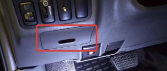
Dismantling and replacing the machine
Dismantling and replacing the auto fuse is carried out with the battery terminal removed, using tweezers. The driver’s main task is to select the necessary components that meet the requirements for the electrical circuit, as well as to replace them when the on-board power is turned off.
It is carried out in the following sequence:
- all devices are turned off;
- the battery is turned off;
- The fuse is replaced using tweezers;
- power is connected.
Many drivers consider these measures excessive, but it is better to take care of safety, especially for beginners. After disconnecting the battery, you may need to reactivate the device. The problem with the same Avensis is that every time the power is turned off, a new ERC code is required, that is, unlocking the car radio.
The service costs about 300 rubles at the service station, so the fuses need to be changed either while the network is on, having first turned off the devices, or this responsibility must be assigned to the service station. So you can find out where the auto fuse is located, but as a result of replacement, a number of other problems arise.
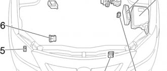
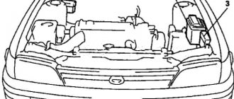
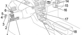
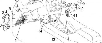
Blocks under the hood
Location
General layout of electronic control units under the hood
Option A
(1AZ-FSE, 1AZ-FE, 1ZZ-FE, 3ZZ-FE)
Option B
(1CD-FTV)
Description
- Injector control unit
- Additional fuse block
- Fuse and relay box
- Left headlight control unit
- Relay block
- Headlight wiper relay
- Right headlight control unit
- Brake system control unit (VSC)
- Brake control unit (without VSC)
- Glow plug relay
- Auxiliary heater
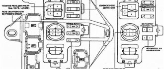
Fuse and relay box
Located on the left side of the engine compartment.
Scheme
Option A
Option B
Designation
| 1 | — |
| 2 | 25A VSC - 1CD–FTV: ABS, VSC |
| 25A ABS - 1CD–FTV: ABS | |
| 3 | — |
| 4 | — |
| 5 | — |
| 6 | 7.5A ALT-S - Charging system |
| 7 | 30A DCC - Fuses: "ECU-B NO.2", "DOME", "RAD NO.2" |
| 8 | 30A AM2 - Starting system, fuses: "ST", "IGN" |
| 9 | 10A HAZARD - Direction indicators, hazard warning lights |
| 10 | 25A F-HTR - 1CD–FTV: Fuel heating |
| 11 | 15A HORN - Horn |
| 12 | 20A EFI - Multiport fuel injection system/sequential multiport fuel injection system, fuses: "EFI NO.1", "EFI NO.2" |
| 13 | 25A PWR HTR - 1CD–FTV: Auxiliary heater |
| 14 | 30A RR DEF - Heated rear window |
| 15 | 40A MAIN - Headlight Cleaners, Headlights, Fuses: "H-LP HI LH", "H-LP HI RH", "H-LP LH", "H-LP RH" |
| 16 | 50A AM1 NO.1 - 1CD–FTV: fuses: "ACC", "CIG", "RAD NO.1", "ECU-B NO.1", "FL P/W", "FR P/W", "RL P/W", "RR P/W" |
| 17 | 30A H/CLN - Headlight cleaners |
| 18 | 40A HTR - Air conditioning. heater |
| 19 | 30A CDS - Cooling fan |
| 20 | 40A RDI - 1CD–FTV, 1ZZ-FE, 3ZZ-FE: Cooling fan |
| 30A RDI - 1AZ-FE, 1AZ-FSE: Cooling fan | |
| 21 | 50A VSC - 1CD–FTV: ABS, VSC |
| 40A ABS - 1CD–FTV: ABS | |
| 22 | 15A IG2 - 1AZ-FSE, 1AZ-FE, 1ZZ-FE, 3ZZ-FE: Starting system, multiport fuel injection system/sequential multiport fuel injection system |
| 23 | 10A THROTTLE - 1AZ-FSE, 1AZ-FE, 1ZZ-FE, 3ZZ-FE: Electronic throttle control system |
| 10A ETCS - 1AZ-FSE, 1AZ-FE, 1ZZ-FE, 3ZZ-FE: Electronic Throttle Control System | |
| 24 | 20A A/F - 1AZ-FSE, 1AZ-FE: Air-fuel ratio sensor |
| 25 | 1AZ-FSE, 1AZ-FE, 1ZZ-FE, 3ZZ-FE: — |
| 26 | 1AZ-FSE, 1AZ-FE, 1ZZ-FE, 3ZZ-FE: — |
| 27 | 50A EMPS - 1ZZ-FE, 3ZZ-FE: Power steering |
| Relay | |
| R1 | EFI MAIN - 1CD–FTV: Cooling fan |
| R2 | EDU - 1CD–FTV: Cooling fan |
| R3 | FAN NO.3 - 1CD–FTV: Cooling fan |
| R4 | FAN NO.1 - Cooling fan |
| R5 | FAN NO.2 - 1AZ-FSE, 1AZ-FE, 1ZZ-FE, 3ZZ-FE: Cooling fan |
| R6 | 1AZ-FSE, 1AZ-FE, 1ZZ-FE, 3ZZ-FE: — |
| R7 | FAN NO.3 - 1AZ-FSE, 1AZ-FE, 1ZZ-FE, 3ZZ-FE: Cooling fan |
| R8 | 1AZ-FSE, 1AZ-FE, 1ZZ-FE, 3ZZ-FE: — |
| R9 | EMPS - 1ZZ-FE, 3ZZ-FE: Power steering |
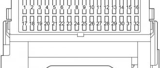
Additional fuse block
Scheme
Option A
Purpose
| 1 | — |
| 2 | 50A HTR2 - Auxiliary heater |
| 3 | 50A HTR1 - Auxiliary heater |
| 4 | 80A GLOW - Glow plugs |
| 5 | 140A ALT - Relay: "IG1", "TAIL", "SEAT HTR", fuses: "H-LP CLN", "AM1 NO.1", "RDI", "CDS", "VSC" (50A), " VSC" (25A), "ABS" (40A), "ABS" (25A), "H/CLN", "RR DEF", "GLOW", "HTR NO1", "HTR NO2", "RFGHTR", " AM1 NO.2", "RR FOG", "S/ROOF", "STOP", "P/POINT", "FR FOG", "OBD2", "DOOR" |
| Relay | |
| R1 | |
| R2 | HTR2 - Auxiliary heater |
| R3 | HTR1 - Auxiliary heater |
Option B
Decoding
| 1 | 10A EFI NO.1 - Multiport fuel injection system / sequential multiport fuel injection system |
| 2 | 7.5A EFI NO.2 - Emission Control System |
| 3 | 25A VSC - ABS, VSC |
| 25A ABS - ABS | |
| 4 | 100A ALT - 1ZZ-FE, 3ZZ-FE: Fuses: "AM1 NO.1", "H-LP CLN", "ABS" (25A), "VSC" (25A), "ABS" (40A), "VSC" "(50 A), "CDS", "RDI", "HTR", "RR DEF", "RR FOG", "FR FOG", "AM1", "DOOR", "STOP", "OBD2", " S/ROOF", "PWR SEAT", "P/POINT", "TAIL", "PANEL", "RR WIP", "ECU-IG", "WIP", "GAUGE2", "GAUGE1", "HTR" "S-HTR" |
| 120A ALT - 1AZ-FSE, 1AZ-FE: Fuses: "AM1 NO.1", "H-LP CLN", "ABS" (25A), "VSC" (25A), "ABS" (40A), "VSC "(50 A), "CDS", "RDI", "HTR", "RR DEF", "RR FOG", "FR FOG", "AM1", "DOOR", "STOP", "OBD2", " S/ROOF", "PWR SEAT", "P/POINT", "TAIL", "PANEL", "RR WIP", "ECU-IG", "WIP", "GAUGE2", "GAUGE1", "HTR" "S-HTR" | |
| 5 | 50A VSC - ABS, VSC |
| 40A ABS - ABS | |
| 6 | 50A AM1 NO.1 - Fuses: “PWR SEAT”, “FR DIC”, “FUEL OPN”, “ECU-B 1″, P-RR P/W”, “P-FR P/W”, “D- RR P/W", "D-FR P/W" |
| 7 | 30A H-LP CLN – Headlight cleaners |
| Relay | |
| R1 | INJ - Injector |
| R2 | EFI - Engine Control Module |
| R3 | IG2 - Ignition |
| R4 | A/F - Air-fuel ratio sensor |
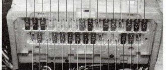
Relay block
Photo - example
Scheme
Description
| 1 | 10A H-LP HI LH - Left headlight (high beam) |
| 2 | 10A H-LP HI RH - Right headlight (high beam), instrument cluster |
| 3 | 15A H-LP LH - Left headlight (low beam) |
| 4 | 15A H-LP RH - Right headlight (low beam) |
| Relay | |
| R1 | HORN - Horn |
| R2 | F-HTR - Fuel heating |
| R3 | H-LP - Headlights |
| R4 | DIM - Dimmer |
| R5 | FAN NO.2 - Cooling fan |
If you have anything to add, write it in the comments.
Fuse diagrams for Toyota Avensis of three generations
The same safety blocks are used for the Toyota Avensis model range of the same generation. There are minor differences regarding power supply circuits, but this applies to vehicles manufactured since 2009. Now we are faced with the task of considering the safety blocks, where they are located, their circuits and installation for different generations of Avensis.