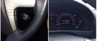
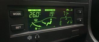
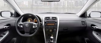
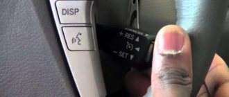
Japanese cars are distinguished not only by increased reliability, but also by comfort. And one of the proofs of this is climate control in Camry, automatically providing a comfortable temperature for the driver and passengers. The basis of a car’s climate system is a control unit, which also controls the temperature and direction of airflow. But it does not last forever, and may fail during operation.
Climate control Camry
Features of self-diagnosis of climate control in cars
If freon and oil leak out, this will require financial costs that cannot be called small. The reasons for system failure vary. Self-diagnosis of climate control allows you to determine the malfunction without the intervention of specialists and unnecessary expenses and try to solve the problem yourself.
How is diagnosis carried out?
Most often, sensors fail, which are quite vulnerable elements and therefore require regular checking. In addition, the fan or air conditioning compressor may break. Regardless of the reason, the result will be the same: discomfort due to too high/low temperature, lack of visibility due to fogged windows, polluted air entering the cabin. In order to identify the source of the problem, our technicians check it with a diagnostic scanner. The latter is connected after the car’s ignition is turned off and data reading is started.
In this case, the diagnosis of Toyota climate control is based on receiving error codes recorded by its electronic control module. Having decrypted them correctly, you can obtain the necessary data. In addition, you can start a mode in which the system independently checks the status of sensors, damper actuators, relays, and fans, displaying the data on the monitor. The price of the service depends on its complexity and volume.
Find out our basic tariffs in the price list or check the numbers with our information line operators: +7 (495) 308‑94‑57.
Troubleshooting
Self-diagnosis of climate control may be required if the device fails and the normal level of comfort in the car interior is disrupted.
The main sources of problems are:
- sensors;
- fan;
- compressor.
It is not always possible to visually determine the presence of faults. For a simple check, sometimes it is necessary to completely disassemble the system. If the breakdown is hidden in the wrong place, the driver will be seriously disappointed, because he had to do such work in vain.
In order not to needlessly disassemble the interior, modern systems on cars have provided a self-diagnosis function for climate control. Automakers install approximately identical devices on cars, which simplifies their installation during vehicle assembly, further repairs and maintenance.
There may be some differences between car climate control systems. But mostly it's about power and design. Their operating principle is the same.
Before checking the climate control in cars, be sure to read the operating manual for your particular car. The manufacturer provides recommendations for maintenance and repair, and instructions for enabling the self-diagnosis mode on specific climate control equipment.
Scanner check
Some people test climate control using a plug-in diagnostic scan tool. In this case, the work has the following sequence:
- turn off the car ignition;
- connect an external scanner to check;
- find the recirculation button and the opposite key (on the right or left in the corner);
- simultaneously press the key with the ignition settings without starting the engine.
After this, the scanner will begin reading data, and records about the start of diagnostics will appear on the screen. The device will automatically check it and display errors in the form of digital codes.
But external scanners do not always provide accurate information. Plus, modern climate systems allow you to launch a self-diagnosis mode without the participation of external testers and check everything in a matter of minutes.
Checking without a scanner
Self-test instructions may vary slightly. But usually there is no fundamental difference. Therefore, we suggest looking at the procedure for launching diagnostics using the example of climate controls installed on Toyota cars.
If you want to check the current status of the equipment, then proceed in the following sequence:
- turn off the ignition;
- hold down the Auto button and the button to select the air intake mode (internal or external) and turn on the engine;
- the panel indicators should light up 4 times, and the interval between them will be 1 second;
- To exit the diagnostic mode, press the Off button;
- when the indicators are checked, diagnostics of the condition of the climate control sensors will begin;
- to check the drives, hold down the air intake mode selection key;
- The drives should be checked when the engine is warm;
- to slow down the test mode, press the button to turn on the heated windshield;
- at one-second intervals, the damper drives, relays and system fan will start to turn on;
- to switch to diagnostic mode, press the Auto button;
- you will see the result of the test on the screen where the temperature is displayed;
- if the display shows 2 codes or more, the indication is carried out from the lower value;
- To complete the procedure, click on Off.
If you managed to eliminate all the faults reported by the system based on the results of the self-diagnosis, do not forget to clear the memory. To do this, you need to press the buttons to turn on the heated rear and front windows. This is done simultaneously.
Although many car owners advise doing otherwise. To turn on the mode for checking the climate control equipment for malfunctions, turn off the ignition, hold down the Auto button and the button for turning on the external circulation (the arrow is drawn outside the cabin). Without releasing these buttons, you need to start the car by turning the key in the ignition.
The screen will begin to flash, indicating diagnostics are in progress. When the test is completed, the corresponding digital values will appear on the screen. Errors are encrypted in these codes, with the help of which you can understand what kind of malfunctions we are talking about.
If you see two zeros on the screen, then there are no problems with the climate control.
Car scanners
It's easy to get lost among the variety of scanning devices.
To diagnose Rav 4 error codes, both hardware types of devices and scanners from the adapter are used.
Scan Tool Pro is one of them. This instrument is easy to operate and suitable for initial analysis. The scanner is universal. Connects to any type of device running on operating systems such as iOS, Android, Windows, via the standard OBDII protocol.
Pros of Scan Tool Pro:
- compactness,
- versatility,
- ability to save and print out error codes,
- Compatible with Rav 4.
Launch CReader V+ is already equipped with a bright LCD screen and does not require additional connection to devices. The test results are displayed on the screen in the form of text and graphic blocks reflecting the dependence of the values.
Advantages of Launch CReader V+:
- absolute autonomy;
- displaying indicators online;
- long service life;
- ease of operation.
Delphi DS150E is the leader among affordable automotive scanners. The device is universal and works using the Generic OBD or eOBD protocols, and also scans available car units. When performing dynamic scanning, data is transferred to a memory card, which is installed in a special slot.
The Delphi DS150E has many features for an affordable automotive scanner, often used in service stations. Some users consider the too large size of the device to be a disadvantage.
Self-diagnosis procedure
This function is available if the climate control on the Camry 40 is equipped with a unit with an LCD display. On older versions of units, diagnostics can only be carried out using a car scanner by connecting to the standard connector located near the steering column.
Self-diagnosis procedure
We are trying to carry out self-diagnosis of the climate systems in the car, you need to perform the following steps:
- Turn off the engine, turn off the ignition.
- Simultaneously press the Auto button on the climate control panel and the button that activates internal air circulation.
- While holding the buttons, turn on the ignition. At the same time, all indicators located on the remote control display will begin to blink, which indicates the start of the self-diagnosis process.
- After checking the display and diagnostics of the sensors, an error code will be displayed on the display in the place where the temperature is normally displayed.
- If 2 or more errors occur, they are displayed alternately, starting with the smallest code.
The climate control on the Toyota Camry is equipped with a considerable number of electric drives, the functionality of which can be checked by switching to self-diagnosis mode. To do this you need:
- Start the system self-diagnosis process as described above, then press the button that activates air circulation inside the cabin. Important: diagnostics must be performed on a fully warmed-up internal combustion engine.
- During the test, various fan operating modes will turn on alternately, with a delay of 1 second, and the dampers will open/close.
- You can increase the interval for changing modes by pressing the windshield defogger button.
- To exit the test mode for drives, relays and fans, press the AUTO button - in this case, the control unit will switch to the sensor test mode.
A little about compressor blocking
Blocking the compressor does not mean that it is jammed as a result of foreign objects getting inside.
Compressor blocking
The fact is that when the electromagnetic clutch is turned off, only the pulley rotates with the drive belt. And after pressing the AC key on the climate control unit, its signal activates the electromagnetic clutch, connecting the pulley and the rest of the compressor mechanism. Its rotation frequency is controlled by a special sensor, which transmits signals to the ECU. If a discrepancy between the compressor rotation speed and the engine speed is detected by more than 20%, the climate control unit will automatically turn off the electromagnetic clutch, thereby stopping the compressor. In this case, the AC indicator light on the climate panel will begin to flash once per second.
Therefore, if, when you turn on the air conditioner, warm air blows from the air ducts, and the climate control on the Toyota Camry 40 shows an AC error, then the first thing you should do is check the condition of the belt and its tension.
Decoding climate control self-diagnosis codes
Thanks to Alexey ( kalex
) for the information provided.
To access the error memory, simultaneously press the [Recycle]+[ECON] buttons and hold them for more than 3 seconds. A three-digit error code will appear on the left, and the number “00” on the right. After pressing [Temp. +] the following error code appears. If code 000 appears on the left, then there are no other errors in memory. Press [ECON] for about 3 seconds. erase the errors, code 444 will appear on the display. To return to normal display mode, press [ECON].
Error codes VAG code - Climate display - Error source 00281 —- 119 ——————— Travel speed sensor-G68 00532 —- 214 ——————— Power supply voltage 00538 —- 21A ——————— Reference voltage 01296 —- 510 ——————— Central vent temperature sensor-G191 01297 —- 511 ——————— Footwell vent temperature sensor-G192 00779 —- 30B ——————— Sensor outside air temperature-G17 00785 —- 311 ——————— Front panel temperature sensor-G56 00787 —- 313 ——————— Fresh air intake duct temperature sensor-G89 00792 —- 318 ————— —— Pressure sensor in the air conditioner circuit-F129 00796 —- 31C ——————— Temperature sensor fan-V42 00797 —- 31D ——————— Solar radiation intensity photo sensor-G107 00818 —- 332 ——— ———— Evaporator outlet temperature sensor-G263 00819 —- 333 ——————— High pressure sensor-G65 00898 —- 382 ——————— Control signal supply to air conditioning compressor 01271 —- 4F7 —— ————— Air temperature control damper control motor-V68 01272 —- 4F8 ——————— Central damper control motor-V70 01273 —- 4F9 ——————— Supply fan-V2 01274 —- 4FA — —————— Air intake flap control motor-V71 01206 —- 4B6 ——————— No signal for timing “ignition off” 00603 —- 25B ——————— Footwell flap control motor defrost flap-V85 01582 —- 62E ——————— Coolant temperature signal 01336 —- 538 ——————— Comfort data bus 01341 —- 53D ——————— Instrument cluster control unit on Comfort CAN bus-J285 01299 —- 513 ——————— Data bus diagnostic interface-J533 01198 —- 4AE ——————— Comfort data bus: incorrect software version 01044 —- 414 ———— ——— Control unit 01087 is incorrectly coded —- 43F ——————— Basic settings not completed no ——- 444 ——————— No errors detected
Climatronic - Service mode
We enter the service mode by simultaneously pressing [ECON] + + [Fan speed is lower] After pressing [ECON], we return to normal mode.
00 General level, 0 = max. cool, 255 = max. warm 01 Temperature control (on the climate control panel) 02 Solar irradiation index averaged 03 Solar irradiation index in mW/cm² 04 Bumper temperature averaged 05 Bumper temperature current value 06 Temperature in the fresh air intake duct 07 Foot air temperature 08 Center air temperature 09 Set voltage value fan 10 Actual fan voltage value in 10-1 Volt 11 Temp. damper, 0 = max. heating, 255 = max. cold) 12 Middle damper, 0 = feet-/defrost, 255 = middle 13 Air pressure damper, 0 = circulation, 255 = fresh air 14 Foot-/defrost damper, 0 = wind. glass, 255 = legs 15 Time after starting the engine in sec. 16 Speed in km/h 17 ? goes from a negative (cool) or positive value (heat) to 0 18 ? most often = 0, when it is very hot that the cooling fan also starts, then the value is in the range of approx. 68 19 Compressor cut-out condition, 0 = none, 5 = low speed, 6 = ECON, 7 = OFF, 11 = ?, 12 = ? 20 ? Adjustment parameter 0 to 100, 100 = max. cool or heat 21 ? starts around 0 22 ? Adjustment parameter, small values approx. 0 23 Actual value of the blowing temperature in the middle 24 Set value of the blowing temperature in the middle 25 Temperature damper - end position warm 26 Actual value of the temperature damper 27 Temperature damper - end position cold 28 Central damper - end position foot/defrost 29 Actual value of the central damper 30 Central damper end position middle 31 Blower flap end position circulation 32 Actual value of the blower flap 33 Blower damper end position fresh air 34 Foot flap/defrost end position defrost 35 Actual value of the foot flap/defrost 36 Foot flap/defrost end leg position 37 Downtime in minutes (ignition off) 0 to 240 min. 38? = 20 39 Time after switching on. ignition in steps of 4 seconds. 40 Adjustment deviation 41 ? = 0 42 ? = 8 43 ? = 0 44 ? = 0
The cost of diagnosing errors for Ford at service stations in Moscow and St. Petersburg
Approximate prices for computer diagnostics of faults:
| City | Company name | Address | Phone number | Price |
| Moscow | North Motors | St. Dubninskaya, 83 | +7 | 2500 rub. |
| Silver elephant | St. Pyalovskaya, 7 | +7 | 3500 rub. | |
| Saint Petersburg | Automagic | St. Uchitelskaya, 23 | +7 | 2000 rub. |
| ClinliCar | Bolshoy Sampsonievsky Ave., 61k2 | +7 | 3000 rub. |
If there is a message on the dashboard about a malfunction of the airbag system, you should definitely check which elements and sensors are faulty or there is no communication with them. The resistance of the airbag and belt pretensioner squib can be checked with a multimeter, it is about 2 ohms. Error codes with explanations are given in the table.
Error manifestation and engine “behavior”
If there is something wrong with the TPS sensor, the ECM will receive incorrect throttle position data or no throttle position data at all. The electronic control unit will be “misled” by this and, at best, will begin to control the operation of the engine, “focusing” on incorrect TPS readings, and at worst, it will eliminate the TPS readings and light up the “CHEK” light, i.e. error code 41. Both These operating options will adversely affect the dynamics of the car, which cannot but be noticed by the driver.
Vehicle malfunctions due to incorrect adjustment or breakdown of the TPS will manifest themselves in “sluggish” and unreliable engine starting, increased fuel consumption, increased idle speed, and “failures” when accelerating. And in a car with an automatic transmission, “jerking” will begin when switching “speeds”, will not engage or will be difficult to engage in an upshift.
Since Toyotas mostly have automatic transmissions, a malfunction or violation of the TPS adjustment will result in the most widespread and unpleasant defect. It will manifest itself in the absence or delay of gear shifting, which will become especially noticeable when moving from a standstill and picking up speed: the tachometer goes off scale at three thousand revolutions, and the car is still moving in first gear.
Faults associated with TPS (error 41 Toyota) include:
- noticeable increase in idle speed;
- deterioration in fuel efficiency;
- slow automatic transmission gear shifting;
- automatic transmission shifting with knocking and jerking noises
- inadequate response to a sharp press on the gas pedal, etc.
Why is it necessary to check the system status regularly?
Climate control is a complex consisting of devices that provide a comfortable microclimate in the cabin. It includes air conditioning, heating and air filtration systems, as well as sensors located in different parts of the body. Its “brain” is an electronic control module that processes data received from sensors and automatically adjusts the temperature.
Unlike a conventional car air conditioner, it is almost completely autonomous: the driver does not need to set the desired temperature and other parameters - he can completely concentrate on control. Diagnostics of “Toyota” climate control in “Toyota Taganka” is carried out according to plan within the framework of “Toyota” maintenance and provides complete information about its technical condition. It can be ordered urgently if there are malfunctions. In this case, it will allow you to accurately determine the cause of the malfunction.
A competent check of the system’s condition will allow the car owner to eliminate breakdowns in the future. Knowing the service life of its parts, he can plan their repair/replacement and his budget for them. Following the recommendations of our experts, he will optimize the cost of maintaining the machine and extend the service life of the most expensive mechanisms and components.
Self-diagnosis of climate control for Toyota Camry ACV40.
Process:
1. Stop the engine.
2. Simultaneously press and hold the “AUTO” and “Internal air circulation” buttons on the climate control. 3. Turn on the ignition. After checking the indicators, sensor diagnostics will automatically begin. 4. The result of the sensor diagnostics is displayed in the window displaying the set temperature. If there are 2 or more codes, the display starts with the smallest one. 5. To diagnose the drives, press the “Internal air circulation” button. Checking the drives should be carried out on a warm engine. To slow down the test, press the heated front window button. At intervals of 1 second. the damper actuators, fan and relay will operate. To enter the sensor diagnostic mode, press “AUTO”. 6. To complete the diagnostics, press the “OFF” button. Clearing the memory:
After troubleshooting, clear the memory: while diagnosing the sensors, press the “Heated front window” (FRONT) and “Heated rear window” (REAR) buttons simultaneously.
Here's what you need to click to diagnose!
Error codes:
00
- No errors
11
- Cabin temperature sensor
* 12
- Ambient temperature sensor
* 13
- Evaporator temperature sensor
* 14
- Coolant temperature sensor
* 21
- Sunlight sensor (passenger side)
* 22
- Lock sensor compressor
** 23
- Pressure sensor (refrigerant).
*** 24
- Sunlight Sensor (driver's side)
* 31
- Air Mixture Damper Position Sensor (passenger's side)
* 32
- Air Intake Damper Position Sensor
* 33
Outlet Damper Position Sensor Circuit
41
- Air Mixture Damper Servo Motor (with passenger side)
* 42
Damper
Control Servo Motor
46 -
Air Damper Control Servo (driver's side)
51
- Compressor Solenoid Circuit
62 -
Air Humidity Sensor (not on Camry)
71
- A/C Inverter High Voltage Power Resource System Malfunction
72
- A/C Inverter High Voltage Output System Malfunction
73
- A/C Inverter Start-up Signal System Malfunction
75
- A/C Inverter Cooling / Heating System Malfunction
76
- A/C Inverter Load System Malfunction
77
- A/C Inverter Low Voltage Power Resource System Malfunction
97
- BUS IC Communication Malfunction
98
- Communication Malfunction (A/C Inverter Local)
99
- Multiplex Communication Circuit
Note: *:
This sensor or climate control unit is faulty;
The wiring or connectors between this sensor and the climate control are damaged. **:
This sensor or climate control unit is faulty;
The wiring or connectors between this sensor and the climate control are damaged; The compressor drive belt is damaged or not adjusted; The compressor electromagnetic clutch sensor is faulty; The air conditioning compressor is faulty (or the compressor is blocked); The engine control module (ECM) is faulty. ***:
This sensor or climate control control unit is faulty; The wiring or connectors between this sensor and the climate control are damaged; The compressor is faulty (or the compressor is blocked); Leakage, lack of refrigerant or incorrect (lower or higher than normal) pressure in the system. Codes 21 and 24 can pop up if diagnostics are carried out in a dark room or at night. Due to loss of connection with the instrument panel, code 71 cannot be displayed on it. What is “compressor blocking”? Many people do not understand this point. The principle of correct operation is simple. When the compressor is OFF, the accessory drive belt rotates only the accessory drive belt pulley. If the compressor needs to be turned ON, the electromagnetic clutch is activated (the compressor is locked with the pulley and begins to rotate). The brain receives a signal from a sensor (similar to the ABS sensor) that the compressor is turned on and rotating. This sensor then transmits pulses to the ECM equal to the engine speed. If the ratio between the compressor and engine speeds deviates by 20% or more from normal operation, the ECM turns off the air conditioning compressor and the indicator begins to flash with period
From the manual
Self-diagnosis of climate control (hereinafter referred to as “CC”) must be launched immediately after turning on the ignition.
Checking the display indication
Checking the display indication To enter mode No. 1, a couple of seconds after turning on the ignition and automatically starting the CC system, press the “OFF” button and hold it until all the indications on the display light up (usually this happens within 5 seconds).
Checking the sensors
To enter mode No. 2, you must press the button to increase the air flow temperature (with a red arrow). The number “2” will light up on the display and a sensor test will begin, usually lasting about 25 seconds.
If all sensors are working normally, at the end of the test the number “20” will appear on the display. If there are errors, then instead of the zero after the two, another number (1-6) will be displayed, corresponding to the error code.
If several errors are detected at once, the numbers after the two will alternate (for example: 21…25…21)
Description of the error
When carrying out the self-diagnosis procedure indoors or in the shade, you can use a 60 W lamp to check the sensor, which should be shined on the windshield.
Checking air damper actuators
To enter mode No. 3, you must press the button to increase the air flow temperature. The number “3” will light up on the display and the test will begin, usually lasting about 50 seconds.
During the test, you will probably hear characteristic sounds of the damper servos operating.
If the dampers operate normally in all modes, at the end of the test the number “30” will appear on the display. If there are errors, the corresponding error code will be displayed after the three, similar to mode No. 2.
If several errors are detected at once, the numbers after the three will alternate.
Error codes in mode
Checking the operating modes of the QC system
To enter mode No. 4, you must press the button to increase the air flow temperature, after which the numbers “41” should appear on the display.
In the future, when you press the button for forced windshield blowing, the operating modes should switch, accompanied by a sequential change in the display in the range from 41 to 46.
Diagnostics in this mode is carried out by the user himself by monitoring extraneous noise in the operation of the fan, assessing the power and temperature of the discharge air flow in accordance with the table below.
Climate control panel does not work
Good day, forum users! Tell me who knows. For several months, the climate control control panel was periodically switched off. I was on a business trip for two weeks, returned, the climate control went silent and the panel did not turn on. The clock on top is shining, but the entire control panel for the stove and air conditioner is silent. Maybe you can point me where to look to fix it. Body zze-124, 2001
There are 10 replies to this topic
Look in the book, find out which fuse, look at it. If it periodically disappears, it means most likely a wire break. Ring the wires.
Power is supplied through three fuses. SIG, DOME and GAUGE. Look at them and call the wires from them to the connector in the control unit.
I have the same bullshit. We called everything possible, everything is in order, but the climate control didn’t work. Can someone send me a climate control diagram? I'd like to call her...
The diagram of the control unit itself is probably not publicly available. At least I didn't find it. It’s easier to find a car with the same control unit, which is known to work. Try to transfer it, if everything works, find the contract control unit.
I'm shocked. Today the car sat in the sun for half a day. After this the climate control started working. What was it, I don’t understand?
In this case, the most likely reason is a defect in the soldering or conductive path on the board. A very nasty malfunction, which, if the damage is not obvious, is very difficult to find. As an option, looking at their soldering under a magnifying glass, move the loose and most massive elements (electrolytes and the like) and connectors, those that are easily loosened by vibration and those that are subject to maximum physical stress. Well, as a last resort, blow out the entire board with a soldering hair dryer. But this is fraught with overheating of the elements and something can generally be blown away.
Yeah. After standing in the garage for half a day, everything disappeared again. Well, there’s nothing to do, I took it off, took it all apart, took a hairdryer from my wife and used it to heat the boards. I assembled it and oh miracle, it works again. Tomorrow morning I'll take a look now to see what it shows after the night. If so, then you will have to remove it and re-solder everything carefully.
A human or woman's hairdryer will not heat up properly, it will only help temporarily. You need a special soldering hair dryer.
Good afternoon. Did you manage to solve this problem in due time? I have exactly the same problem with the same symptoms.
online now
No car club members
based on activity data for the last 5 minutes.
