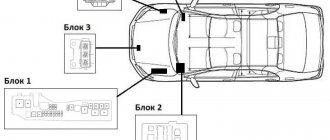
Toyota Camry 30 fuses, located in the passenger compartment and engine compartment, protect the electronics and wiring harnesses from damage due to short circuits. To replace elements, tweezers are required; the wiring diagram is shown on the covers of the junction boxes.
Purpose of the system
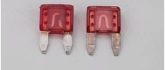
Blade-type fuses located in the wiring boxes of the Camry V30 provide protection for electrical circuits from increased current.
If the insulation is damaged or equipment with increased power is connected, the current passing through the metal jumper increases. The element heats up to the melting point and breaks the circuit, interrupting the power supply.
The fuses used in the machine are:
- knife type A;
- case type B;
- case type C, designed for increased current.
The nuances of using the cigarette lighter and sockets
Often a cigarette lighter is used to power gadgets, but to properly operate the device without damaging the car’s electrical network, a number of nuances must be taken into account.
If you wish to use outlets and power strips powered by the cigarette lighter, ensure that the maximum total load supported does not exceed the load capacity of the cigarette lighter circuit. The Camry XV40 cigarette lighter fuse is designed for a maximum current of 20A. This indicator must be taken into account when choosing a splitter.
If your cigarette lighter plug is constantly burning in your Toyota Camry 40 2006-2011, immediately contact a professional technician specializing in automotive electronics. This will allow you to detect the malfunction in time and eliminate it before the malfunction causes a fire.
look at the window regulators (buttons to lower and raise the windows), could this be why the central locking may not work?? because a couple of wires from the lock go to it.... No. 32 for 30 A
Fuse box diagram and location
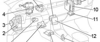
The vehicle design has several fuse blocks:
- in the engine compartment;
- in the instrument panel.
Salon compartment
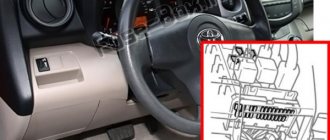
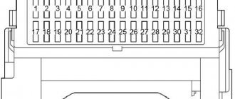
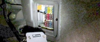
The mounting box is fixed at the bottom of the instrument panel on the driver's left foot side. To access the protective elements, you need to remove the rectangular plastic cover, which is held in place by elastic clips. On the inside of the plug there is a diagram of the fuses (the number of elements depends on the level of equipment of the car).
List, denomination and purpose of type A elements located inside the car (top to bottom and left to right):
- Electric lock drives, standard security system, interior lighting, rear fog lamp and air conditioning fan (10 A).
- Interior lighting and ignition lock cylinder, electronic clock and multifunction computer display (7.5 A).
- Cigarette lighter socket (15 A).
- Electric drives for rear-view mirrors and additional power circuits for the clock and display (5 A).
- Standard radio (10 A).
- Socket for additional equipment (15 A).
- Additional power supply for the radio (20 A).
- Instrument cluster, electromagnetic gearbox selector lock (10 A).
- ABS system and airbags, controls for electric window drives (10 A).
- Windshield cleaning system (25 A).
- Air conditioning (10 A).
- Heated mirrors (10 A).
- Fuel injection and engine starting system (5 A).
- Front fog lights (15 A).
- Rear electric sun shade (optional, 15 A).
- Interior mirror, cruise control unit and electric sunroof drive (optional, 10 A).
- Illumination system for the glove box and elements on the instrument panel (10 A).
- Side lighting (10 A).
- Electric window on the rear left side (20 A).
- Power window on the front passenger side (20 A).
- Diagnostic block (7.5 A).
- Heated front seats (20 A).
- Electric windshield washer pump (15 A).
- Electric cooling fan (10 A).
- Brake light lamps, ABS and cruise control units (15 A).
- Fuel Open lock for fuel tank flap (5 A).
- Body electrical equipment control controller (25 A).
- Sound amplifier (optional, 25 A).
- Electric window on the rear right side (20 A).
Purpose and rating of type B elements in the cabin:
- Driver's door power window and sunroof (30A).
- Electric seat adjustment drives for driver and passenger (30 A).
- Def, heated rear window (40 A).
Engine compartment
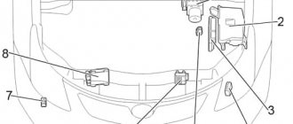
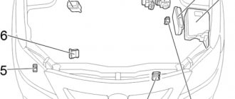
The main unit in the engine compartment is located in the gap between the front right pillar support and the battery. The top of the box is closed with a plastic casing with spring clips. The additional module is installed in the gap between the battery and the radiator block of the engine cooling and air conditioning systems in the cabin.
The location of the blocks under the hood does not depend on the number of engine cylinders and the type of transmission.
List and rating of type A elements installed in the main block (from top to bottom and from left to right):
- Low beam left headlight (15 A).
- Low beam of the right headlight and beam position corrector (15 A).
- Daytime running lights (optional, 5 A).
- ABS controller and course stabilization system (7.5 A).
- Reserve (10 A).
- Reserve (15 A).
- Reserve (5 A).
- Ignition system (30 A).
- High beam on the right (10 a).
- High beam on the left (10 A).
- Fuel injection system (5 A).
- Telephone (optional, 5 A).
- Charging the battery (5 A).
- Motor starting system (15 A).
- Fuel injection and security systems (10 A).
- Door locks (25 A).
- Fuel injection system (20 A).
- Klaxon (10 A).
- Engine and head unit controllers (Ecu B, Rad and Dome) (30 A).
- Manifold gasoline injection system controller (25 A).
- Additional circuits providing fuel supply (10 A).
- Hazard warning lights (15 A).
Purpose and rating of type B elements in the engine compartment:
- Protection for headlights and daytime running lights (40 A).
- Controllers for ABS, directional stability and traction control systems (40 A).
- Electric cooling fan motor (30 A).
- Auxiliary cooling fan motor (30 A).
- Air conditioning control (50 A).
- Headlight cleaning unit (30 A).
- Additional circuits for ABS, directional stability and traction control systems (30 A).
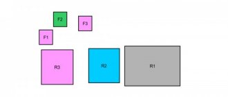
At the top of the unit there is a 120 A Type C power element, which provides general protection for the vehicle's electrical circuits. Nearby there is a 50 A type C insert that prevents failure of the ABS unit. A single 7.5 A Type A element is located in a separate, compact unit in front of the radiator. The part protects the anti-lock brake system (ABS) unit and maintains the functionality of the traction control system. The ABS auxiliary relays are located nearby.
Blocks under the hood
Main block
Under the hood, the main block with fuses and relays is located on the left side of the engine compartment.
Scheme
Purpose
| 1 | 100A ALT - 2AZ-FE (2002-2003): Fuses: “DEF”, “PWR NO.1”, “PWR NO.2”, “PWR NO.3”, “PWR NO.4”, “STOP”, “DOOR NO.2”, “OBD”, “PWR SEAT”, “FUEL OPEN”, “FOG”, “AMP”, “PANEL”, “TAIL”, “AM1”, “CIG”, “POWER POINT”, “RAD NO.2”, “ECU-ACC”, “GAUGE1”, “GAUGE2”, “ECU-IG”, “WIPER”, “WASHER”, “HTR (10 A)”, “SEAT HTR”, and “ SUN-SHADE" |
| 120A ALT - 1MZ-FE, 3MZ-FE, 2AZ-FE (2003-2006): Fuses: DEF”, “PWR NO.1”, “PWR NO.2”, “PWR NO.3”, “PWR NO. 4”, “STOP”, “DOOR NO.2”, “OBD”, “PWR SEAT”, “FUEL OPEN”, “FOG”, “AMP”, “PANEL”, “TAIL”, “AM1”, “CIG” ”, “POWER POINT”, “RAD NO.2”, “ECU-ACC”, “GAUGE1”, “GAUGE2”, “ECU-IG”, “WIPER”, “WASHER”, “HTR (10 A)”, "SEAT HTR" and "SUN-SHADE" | |
| 2 | 60A ABS NO.1 2002-2003: Anti-lock braking system, vehicle stabilization system, traction control, brake assist system |
| 50A ABS NO.1 - 2003-2006: Anti-lock braking system, vehicle stabilization system, traction control, brake assist system | |
| 3 | 15A HEAD LH LWR - Low left beam, instrument cluster, fog light, body electrical control unit |
| 4 | 15A HEAD RH LWR - Low right beam, headlight corrector, body electrical control unit |
| 5 | 5A DRL - Daytime running lights |
| 6 | 10A A/C - Air conditioning |
| 7 | Not used |
| 8 | Not used |
| 9 | Not used |
| 10 | 40A MAIN - Fuses: “HEAD LH LWR”, “HEAD RH LWR”, “HEAD LH UPR”, “HEAD LH UPR” and “DRL” |
| 11 | 40A ABS No.2 - Anti-lock braking system, vehicle stabilization system, traction control, brake assist system |
| 12 | 30A RDI - Engine cooling fan |
| 13 | 30A CDS - Air conditioning fan |
| 14 | 50A HTR – Air conditioning |
| 15 | 30A ADJ PDL - Electric gas pedal |
| 16 | 30A ABS No.3 - Anti-lock braking system, vehicle stabilization system, traction control, brake assist system |
| 17 | 30A AM2 - Starting system, fuses: “IGN” and “IG2” |
| 18 | 10A HEAD LH UPR - High left beam |
| 19 | 10A HEAD RH UPR - High right beam |
| 20 | 5A ST - Instrument cluster, starter, ignition |
| 21 | 5A TEL - Telephone |
| 22 | 5A ALT-S - Battery charging system |
| 23 | 15A IGN - Starting system |
| 24 | 10A IGN2 - Anti-lock braking system. battery charging system, instrument cluster, cruise control, transmission control unit, automatic transmission indicator, engine control unit, seat belt indicator, vehicle stability control, traction control |
| 25 | 25A DOOR1 - Body electrical equipment control unit, anti-theft system, central locking, central locking control unit |
| 26 | 20A EFI - Cruise control, transmission control unit, automatic transmission indicator, engine control unit |
| 27 | 10A HORN - Horn |
| 28 | 30A DCC - Fuses: “ECU-B”, “RAD NO.1” and “DOME” |
| 29 | 25A A/F - Engine control unit |
| 30 | Not used |
| 31 | 10A ETCS - Engine control unit, cruise control |
| 32 | 15A HAZ - Direction indicators, hazard warning lights |
| R1 | Not used |
| R2 | Not used |
| R3 | Daytime running lights (No.2) |
| R4 | Daytime running lights (No.3) |
| R5 | Cooling Fan (No.2) |
| R6 | Daytime running lights (No.4) |
| R7 | Electric gas pedal |
| R8 | Cooling Fan (No.3) |
| R9 | A/C compressor clutch |
| R10 | Air fuel ratio sensor |
| R11 | Air conditioner |
| R12 | Starter/ignition |
| R13 | Headlights |
| R14 | Cooling Fan (No.1) |
| R15 | Vacuum valve (VSV) |
| R16 | Sound signal |
| R17 | The engine control unit |
About replacing fuses
To remove the burnt protective element, tweezers are used, stored in a block under the hood. The manufacturer allows the use of fuses with the rating specified in the wiring diagram. If there is no spare element with the required parameter, temporary use of a part with a reduced rating is allowed. In this case, when the electrical equipment is turned on, the fuse may fail again, which is not a sign of a malfunction of the circuits or devices.
Repeated failure of a fuse with a rated operating parameter indicates a short circuit. It is necessary to check the power circuits in a service center. It is prohibited to use a jumper designed for increased current.
Toyota Camry XV50 - Unit D (Integrated relay)
It so happened that within a fairly short period of time, two new Toyota Camrys , with burnt out units called:
- Integration Relay (Engine Room Junction Block Assembly)
Both cars were after an accident, and one, after repairs, had already driven a certain number of kilometers, and suddenly, in the morning, smoke poured out from under the hood. The block and part of the wiring burned out.
Let's take a closer look at this “Integrated Relay”, which, among other things, performs the function of “protecting” electrical circuits by burning out first.
is labeled Unit D. As you can see, this relay does not have any fuses; its housing is not dismountable.
If you remove the “Integrated Relay” from the fuse block, it is held on by two latches on the sides, then we will see several connectors from below. Let's now understand the purpose of the contacts of these connectors and, in general, what this block is responsible for.
General rules
Before carrying out work to replace Camry 30 fuses, you will need to familiarize yourself with and adhere to the following precautions:
- When working on the Camry 30 electrical network, first remove the negative contact from the battery terminal;
- If you plan to perform control measurements or repair the battery, then initially the negative contact, which is directly fixed to the body, is reset;
- If repair work requires the use of welding, then in addition to disconnecting the battery, you will need to disconnect the power connector of the electronic control unit;
The protective cover of the ECU may only be opened if necessary. The fact is that it is equipped with an integrated circuit that is very sensitive. The circuit may be damaged by static electricity.
Correct replacement of fuse links
Changing the Camry 30 fuses is carried out with all electrical appliances and the ignition turned off. As a replacement, it is necessary to use fuse-links with a regulated rated current. The use of jumpers and similar elements is prohibited. This can cause more serious damage and even cause the Camry 30 to catch fire.
A special tool is used to remove and install Camry 30 fuses. The protective element must be removed and inserted in a straight direction, avoiding loosening and twisting. This helps to expand the contact socket, where the fuse will not be fixed in the future.
If, after changing the fuse link, repeated burnout is observed, then you will need to check the circuit for continuity and short circuit.
Toyota Camry VX 30 is the fifth generation Camry which was produced in 2001, 2002, 2003, 2004, 2005 and 2006. In this article we will show a description of the fuses and relays of the Toyota Camry in the 30 body with block diagrams, photo examples of execution and locations. Let's highlight the cigarette lighter fuse separately.
p, blockquote 1,0,0,0,0 —>
p, blockquote 2,0,0,0,0 —>
The number of elements in the blocks and their location may differ and depend on the configuration, year of manufacture and region of delivery (Japan, American, European). Consult your technical information or the diagrams on the unit cover.
Thermal fuses
Before checking or changing the thermal fuses of the Camry 30, you should de-energize the on-board network by disconnecting the contact from the negative terminal of the battery. Next, the following operations are performed:
- The thermal fuse is removed;
- To turn on the Camry 30 fuse, you will need to insert the needle into a special hole and press;
- Multimeter probes are attached to the fuse terminals to test continuity. Measurements are carried out in resistance measurement mode;
- The lack of conductivity indicates the need to change the protective element. If the thermal fuse still turns off after replacement, you will need to check the circuit for a short circuit.
