The VVT-I valve on the 1ZZ-FE engine can be of a collapsible or non-separable design. It is designed for smooth adjustment of valve timing, which contributes to stable operation of the engine in all modes. In this article we will look at the principle of operation of the sensor, possible malfunctions and ways to eliminate them.
General operating principle of the system
The main control device in this variable valve timing system is the VVTI clutch. By default, engine developers designed the valve opening phases to obtain good thrust at low engine speeds. As the speed increases, the oil pressure also increases, due to which the VVTI valve opens. Toyota Camry and its 2.4 liter engine operate on the same principle.
Once this valve opens, the camshaft will rotate to a specific position relative to the pulley. The cams on the shaft are specially shaped, and as the element rotates, the intake valves will open a little earlier. Accordingly, it will close later. This should have the best effect on the power and torque of the engine at high speeds.
Soft start or Fiat MultiAir, BMW Valvetronic, Nissan VVEL, Toyota Valvematic
If you want smoothness, please, and here the first company in development was (drum roll) – FIAT. Who would have thought, they were the first to create the MultiAir system, it is even more complex, but more accurate.
“Smooth operation” is applied here to the intake valves, and there is no camshaft at all. It is preserved only on the exhaust part, but it also has an effect on the intake (I’m probably confused, but I’ll try to explain).
This allows for smooth activation depending on engine speed. Now many manufacturers also have such developments, such as BMW (Valvetronic), Nissan (VVEL), Toyota (Valvematic). But these systems are not completely ideal, what’s wrong again? Actually, here again there is a timing drive (which takes up about 5% of the power), there is a camshaft and a throttle valve, this again takes a lot of energy, and accordingly steals efficiency, I wish I could give them up.
Sources
https://avtonov.com/vvt-i-%D1%87%D1%82%D0%BE-%D1%8D%D1%82%D0%BE-%D0%B7%D0%B0-%D1% 81%D0%B8%D1%81%D1%82%D0%B5%D0%BC%D0%B0-%D0%BD%D0%B0-toyota/ https://autodata.ru/article/all/sistema_toyota_vvt_i / https://auto-ru.ru/vvti-toyota-chto-eto.html https://bg-moskva.ru/printsip-raboty-mufty-vvti https://systemsauto.ru/vpusk/vvt.html https://car.ru/remont-auto-svoimi-rukami/dvigatel-i-ego-komponenty/28279-klapan-vvt-i-kak-ustroen-i-printsip-deystviya-datchika-faz/ https:// principraboty.ru/vvti-princip-raboty/ https://autodont.ru/grm/vvti https://toyota-camry-corolla.ru/dvigateli/klapan-vvt-i/ https://techautoport.ru/dvigatel /mehanicheskaya-chast/sistema-cvvt.html https://7gear.ru/tuning/vvti.html
Detailed job description
The main control mechanism of the system (this is the clutch) is installed on the engine camshaft pulley. Its body is connected to a sprocket or toothed pulley. The rotor is connected directly to the camshaft. Oil from the lubrication system is supplied from one or both sides to each rotor lobe on the clutch, thereby causing the camshaft to turn. When the engine is not running, the system automatically sets the maximum retard angles. They correspond to the latest opening and closing of the intake valves. When the engine starts, the oil pressure is not strong enough to open the VVTI valve. To avoid any shocks in the system, the rotor is connected to the coupling body with a pin, which, as the lubricant pressure increases, will be pressed out by the oil itself.
The operation of the system is controlled by a special valve. Upon a signal from the ECU, an electric magnet using a plunger will begin to move the spool, thereby passing oil in one direction or the other. When the motor is stopped, this spool moves due to the spring so as to set the maximum delay angle. To rotate the camshaft to a certain angle, high-pressure oil is supplied through a spool to one side of the lobes on the rotor. At the same time, a special cavity opens for drainage. It is located on the other side of the petal. Once the ECU understands that the camshaft has been rotated to the desired angle, the pulley channels overlap and it will continue to be held in this position.
Lifehack Blog VVT-i Diagnostics
How to check the solenoid valve of a gas boiler
This entry is a continuation of the topic about disassembling and troubleshooting the VVT-i controller (Nonsense Blog. VVT-i coupling). Or rather, this is most likely prehistory. Since you first need to diagnose a breakdown, and then defect something, disassemble and repair it. At one time, I quite often had to answer questions regarding the performance of VVTL or VVT, about errors P1349, P1693, etc.
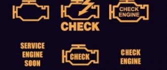
Suddenly, an error message came on telling you to throw out the engine (Check Engine), but nothing special happens, the car just drove and drove, only over time comes the realization that it has become more fuel-consuming and less responsive at medium speeds. Having considered the error, Let's say that you received one of the most common VVT errors, this is P1349 or P1346. If P1349 directly hints at a defect in the VVT mechanism, then P1346 signals an error associated with the camshaft position sensor, but one way or another, it may indicate irregularities in the operation of VVT, for example incorrect Timing phases.
Diagnostics. First of all, it is necessary to determine which node the brain makes for us. Consider the main 3 mechanical malfunctions1. VVT valve filter
A banal mesh, but it can be a little dirty)
and thereby lead to disruption of the VVT2 system. OCV VALVE, aka VVT Solenoid, aka VVT valve
A rather delicate device, which is a several-port solenoid that transfers oil into one channel or another (to advance or retard the shaft).
Many people assume that it works and is controlled according to an algorithm - “closed” - “held pressure” Not quite so. The VVT valve is controlled by the ECU via PWM, and this is done continuously. This is how the valve works in the engine
Although the valve design is commonplace, when working in an aggressive environment, weak points often suffer, for example, deformation of the sealing ring, which leads to sticking of the rod, or weakening of the return spring, which does not return the valve to its original position. And so... we diagnose. We take 2 wires, preferably with connectors
We connect to the valve and to the battery, do not connect the second pole yet
We close the second wire to positive (without fanaticism, short circuits can burn the winding) and listen
It clicks, goes back and forth... If it doesn’t click... then, in principle, everything is clear. However, a small correction. This valve may work fine when you remove it from the engine, but not work in the engine itself. This is due to the fact that the valve can only stick when warm. Therefore, before this test, warm up the engine to operating temperature...
3. VVT couplingAcceptable valve is working. The next Test is the activation of the VVT controller. This can also be done without a dealer scanner. Start the engine and apply voltage to the VVT valve
If there are no changes in the operation of the engine... Then the VVT controller is more likely dead than alive) What should have happened? By applying voltage, you open a channel that brings the VVT Clutch to the position corresponding to the maximum overlap of the intake and exhaust valves.
At idle, the engine cannot operate with such overlap, as the breakthrough of exhaust gases into the intake increases. And the engine stalls.
If the oil pressure in the system is sufficient... then mechanically there is simply nothing left to break.
Wiring, electronics, timing timing and camshaft position sensor. With P1346, you should check whether the timing marks are set correctly, as well as the functionality of the sensor, the integrity of the wiring, whether there is oxidation in the connectors... Well, the worst and most difficult to diagnose is the ECU...
Typical symptoms of VVTI system problems
So, the system must change the phases of operation of the gas distribution mechanism. If any problems arise with it, then the car will not be able to function normally in one or more operating modes. There are several symptoms that indicate a malfunction.
So, the car does not keep idle speed at the same level. This indicates that the VVTI valve is not working as it should. Also, the “braking” of the engine will indicate various problems in the system. Often, if there are problems with this phase change mechanism, the motor is not able to operate at low speeds. Error P1349 may also indicate problems with the valve. If the idle speed is high when the power unit is warm, the car does not move at all.
Recommendations
Comments 38
My experience with this problem is as follows. 1) Changed the tensioner of the attachment. Did not help! The rumble at 1450 rpm remains, there is a rattling noise during startup. 2) I drilled holes in the intake manifold in the right places with screws and supposedly screwed on this dangling bar. The situation has not changed. I installed the contract on the manifold, nothing has changed either 3) I changed the Chain, the hydraulic chain tensioner, the damper and tensioner shoes and the VVT-i coupling and the exhaust camshaft sprocket. Everything is Original. Nothing changed. There was only an additional clattering noise when the engine was not fully warmed up. After half an hour of driving, the clattering noise goes away. As if the clutch is cracking. 4) Replaced the VVT-I valve with a new, original one. Nothing changed. I checked the operation of the VVT-i valve, everything is fine, the car stalls. 5) Connecting three scanners did not show any errors. 6) Recapitalized the engine. Boring of cylinders, replacement of all liners. The situation has not changed. 7) We washed the VVT-I valve mesh, the situation did not change. Checked the oil pressure and pressure relief valve in the oil pump. Everything is in excellent condition. The oil pumps as it should, the pressure relief valve works as it should. 9) The pan and oil receiver were, of course, washed during capitalization. Nothing changed. 10) The valve clearances were checked and they were shuffled into the capital. Nothing changed. 11) The spark plugs were changed, the injectors were put under contract, nothing has changed. 12) Flushing the throttle and idle air valve did not give anything. Replacing the throttle didn't do anything either. 13) The generator has been restored. They replaced everything that was possible on it.
What am I doing wrong to solve the problem? I no longer see the point in putting in a contract, since about 60 thousand rubles have been invested in the engine. Almost everything in the engine has been replaced.
Before the capital, there was a problem with a rumble at speed and rattling during hot starting. + Also, when going up a hill, the engine makes an unpleasant sound, as if it is choking. After the engine was overhauled, all these problems were supplemented by a metallic clatter (the ratchet seemed to be out of lock and could not return) on a not fully warmed-up engine. Then it disappears over time when driving and can also accidentally return. The remaining symptoms are identical. Rumble at 1450 rpm, chain rattling when starting up hot and a wild decrease in traction, as if someone was holding it by the ass.
Damn, I don't even know. You seem to have gone through fire, water and copper pipes. I came to the conclusion that the rumble can be caused by the load at idle using steel test. One should take a stethoscope, the other sits in the car and accelerates, simultaneously pressing the gas and brake (but this must be done for a short time!) I think that your clutch is squealing or it was installed incorrectly or the pin in it is worn out. Another variant of the rumble: one of the airbags is tired, the engine sags under load and the exhaust begins to touch the protective clamp.
The pillows are all new and the original ones were installed. There was no rumble immediately after the capital. It has only now begun to appear, 3000 miles after the capitalization. As for the coupling, I have a suspicion that it was somehow installed incorrectly or that it is defective.
Possible causes of valve failure
There are not many main causes of valve failure. There are two that are particularly common. So, the VVTI valve may fail due to breaks in the coil. In this case, the element will not be able to respond correctly to voltage transfers. Diagnosis of the malfunction is easily carried out by checking the resistance measurement of the sensor coil winding.
The second reason why the VVTI (Toyota) valve does not work correctly or does not work at all is jamming in the stem. The cause of such jamming may be simple dirt that has accumulated in the channel over time. It is also possible that the sealing rubber inside the valve is deformed. In this case, restoring the mechanism is very simple - just clean the dirt from there. This can be done by soaking or soaking the element in special liquids.
How to clean the valve?
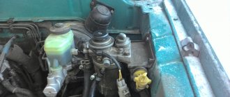
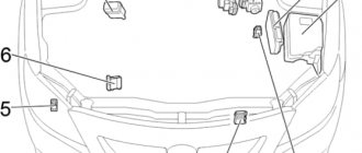
Many problems can be cured by cleaning the sensor. First you need to find the VVTI valve. Where this element is located can be seen in the photo below. It is circled in the picture.
To dismantle the sensor, remove the plastic cover of the power unit. Then remove the metal cover that secures the generator. The required valve will be visible under the cover. You need to disconnect the electrical connector from it and unscrew the bolt. It is very difficult to make a mistake here - this is the only bolt here. The VVTI 1NZ valve can then be removed. But you don't need to pull the connector to do this. It fits very tightly to the sensor. A rubber O-ring is also installed on it.
Cleaning can be done using carburetor cleaning fluids. To completely clean the system, remove the filter. This element is located under the valve - it is a plug in which there is a hole for a hexagon. The filter also needs to be cleaned with this liquid. After all the operations, all that remains is to assemble everything in the reverse order, and then install the generator belt without resting against the valve itself.
FreeValve
Many manufacturers are completely abandoning shafts, throttle and timing drive (chain or belt), but the Swedes were the first to do this in their Koenigsegg supercar, which, by the way, develops as much as 1,500 hp.
How does it work? Instead of shafts, there are special electromagnetic actuators with built-in pneumatic springs. The ECU controls each such valve and is capable of opening and closing it very quickly (up to 100 times per second) and at any distance required. This allows you to adjust the phases to any given value! AND THIS IS REALLY REALLY COOL.
Tests have shown that such a motor is up to 30% more powerful and efficient than analogues with a distribution system, and it is also economical by the same 30%. The ride quality is excellent here.
The downside so far is that such a motor is noisy, so many electromagnetic valves create a clicking sound when opening, and it increases with increasing speed. Also, the cost of the unit is still very high, but if it is put into production, the price could drop significantly.
Well, here we are, looking at the main types of phase shifters and simply gas distribution systems without them. For those who don’t really understand, watch the video version, where I’ll try to explain everything simply and in a simple manner.
Similar news
- Timing chain or belt. What is better, which mechanism drive to choose? ...
- Dirty air filter. What it affects, detailed symptoms and...
- Why is a diesel car more expensive than a gasoline car? More...
How to check the VVTI valve?
Checking whether the valve is working is very simple. To do this, a voltage of 12 V is applied to the sensor contacts. It must be remembered that it is impossible to keep the element under voltage for a long time, since it cannot operate in such modes for so long. When voltage is applied, the rod will retract inward. And when the circuit opens, he will come back.
If the stem moves easily, then the valve is fully operational. It only needs to be washed, lubricated and can be used. If it does not work as it should, then repairing or replacing the VVTI valve will help.
Replacing 1NZ-FE engine mounts on a Toyota Funcargo
The presented report with photographs shows the labor-intensive process of car repair - changing the engine support, which is also called the “pillow”. We will show the process using the example of a Toyota Funcargo.
To change a broken or torn support, you will need the following items for work:
- a set of heads, of which you will need for 10.2 by 14 one simple and long one, for seventeen;
- collar;
- extension cords;
- key for twenty-two;
- wood lining;
- jack;
- hammer;
- stand;
- two flat screwdrivers, 1 small narrow one and an elongated narrow one;
- chisel;
The image shows a torn engine mount.
Before changing the engine mounts, it was necessary to change the gaskets in the middle of the exhaust manifold and muffler. But our problem lies elsewhere - in bent and stuck bolts.
Therefore, we decided that before changing the rear support we need to loosen these bolts. To be brief, the bolts need to be wrapped in a cloth, filled with WD-40 and left to soak for a day. Afterwards, when the engine is cold, in the pit using a strong fourteen socket, an extension and a long 65 cm wrench, first slightly twisting it to the side, then vice versa.
The front of the car needs to be lifted and placed on supports (a log will do). You only need to remove the wheel on the left side.
Remove the lambda probe using a twenty-two key.
Disconnect the sensor from the muffler pipe and the electrical connector by pushing the lever on the connector with an elongated thin screwdriver.
Disconnect the electrical connector from the fastening element on the rear support.
Use a short, thin, flat screwdriver to pry off the lever.
Use a screwdriver to disconnect the latch with the wiring of the lambda probe sensor connector from the support at the rear.
Let's try to break the bolt that holds the engine bracket to the support. You will need a fourteen head, a couple of extensions and a knob. The threads of this bolt should be cleaned and dipped in a WD-40 solution. It is not necessary to hold the nut on the opposite side with a wrench; it has a sidewall “whisker” that keeps it from turning.
It is good to unscrew this bolt from the side of the wheel on the left side.
A key with a strong head that you can build yourself will help you do this job. The longer the better.
This bolt needs to be removed by turning it slightly, but not completely unscrewing it.
Then unscrew the 2 nuts that hold the support bolts using a fourteen socket and a wrench.
The thread of this bolt also needs to be treated with WD. Using a hammer, carefully knock out these bolts.
So why do we need to knock out these bolts? You can't remove the pillow with them; they get in the way because of their length. The bolts are attached to splines in the engine support.
If a problem arises with the bolts, use a chisel, placing its sharp edge in the middle of the bolt head and the steel base of the support mount.
Then we place a jack at the bottom of the rib where the engine connects and lift it slightly. The jack also remains, at this time put supports under the engine. Place it with the lifting handle on the side of the wheels at the back so that later, when you climb under the car, you can raise or lower the engine using a jack.
Then completely unscrew the bolt that holds the engine bracket to the support. Unscrew the remaining bolt holding the support using a 14mm socket and a wrench. The bolt will be a little tight, so play with a jack and level the holes in the engine bracket and support.
This is a bolt holding the engine bracket to the support, and a nut.
What will happen to her when she moves.
You will immediately see gaps in it.
Let's compare the old one and the new one. Knock out the bolts from the new one (pry them out using a chisel and a screwdriver by the heads so as not to damage the threads).
Install a new support. If the hole in the engine bracket and the new support do not meet, lift the engine, insert the bolt and tighten it by hand. After tightening the support at the bottom with a bolt and inserting the remaining bolts at the top, try to match the splines while turning and tighten the nuts. Tighten the nuts and bolt securing the supports and the bolt securing the engine bracket to the support using a torque of 80 Nm. Remove the jack.
Then replace the support on the right. Secure the part of the engine on the right with a jack.
The support on the right is secured with 3 bolts to the side member of the car, and 2 bolts and 1 nut to the bracket on the right of the engine.
It should be noted that the nut must be screwed onto a stud located on the support and on the opposite side of the engine support bracket. It should be unscrewed at the bottom.
For unscrewing, the longest head of fourteen and a pair of extensions with a knob are used. Unscrew the remaining bolts using a 14mm socket, a rod and a knob.
After unscrewing the nuts and bolts, look at the support.
Do-it-yourself valve repair
First, remove the generator control bar. Then remove the hood lock fasteners. This will give access to the generator axle bolt. Next, unscrew the bolt that holds the valve itself and remove it. Then remove the filter. If the last element and valve are dirty, then these parts are cleaned. Repair consists of inspection and lubrication. You can also replace the O-ring. More serious repairs are not possible. If a part doesn't work, it's easier and cheaper to replace it with a new one.
Do-it-yourself VVTI valve replacement
Often cleaning and lubrication do not provide the required result, and then the question arises of completely replacing the part. In addition, after replacement, many car owners claim that the car began to work much better and fuel consumption decreased.
First, remove the generator control bar. Then remove the hood lock fasteners and gain access to the generator bolt. Unscrew the bolt that holds the desired valve. The old element can be pulled out and thrown away, and a new one can be put in place of the old one. Then the bolt is tightened and the car can be driven.