Date: 12/23/2014
Toyota cars equipped with electronic control units (ECUs) of the engine, automatic transmission, ABS, etc., have the ability to perform self-diagnosis. The operating principle of this system is as follows:
- If a deviation from the normal operating mode occurs, the sensor recording it is turned off.
- A bypass program is activated in the ECU, allowing the vehicle to continue operating. When this program is turned on, the alarm light on the display lights up or the system operation lamp in which a breakdown is detected blinks.
- When the malfunction is eliminated (spontaneously or as a result of repair), the bypass program is disabled and the system continues to operate as normal.
- Information about a malfunction that occurs is stored in the form of a special code, which can later be read.
On modern Toyota Corolla cars, the ECU is able to distinguish faults according to the degree of importance for operation, and information about “light” deviations is not recorded. For example, if dirt gets on one of the ABS sensors while driving, and after washing it off, the sensor returns to normal operation, this deviation will not be recorded.
The diagnostic system is very convenient when repairing a car, thanks to it you can quickly identify the cause of problems.
Connectors for diagnostics of Toyota Corolla cars
For self-diagnosis of Toyota Corolla cars, special diagnostic connectors (DLS - DataLinkConnector) are provided, the type and location of which depend on the model and year of manufacture of the vehicle.
DLS 1 is a rectangular plastic box located under the hood of the car on the left. This connector has a corresponding designation on the housing - “DIAGNOSTIC”. Self-diagnosis is carried out using the “CHECK” light located on the instrument panel, the corresponding control lights for vehicle systems or other signaling devices.
The DLS 2 diagnostic connector is located in the passenger compartment: under the front panel on the driver's side. It has a different configuration from DLS 1, as it involves connecting special diagnostic equipment. This connector is convenient because it allows self-diagnosis of a running vehicle.
DLS 3 is also located in the cabin under the dashboard. This type of diagnostic connector is mainly found in cars with a robotic transmission.
Location and types of diagnostic connectors
Cars of the Japanese manufacturer Toyota were equipped with two types of connectors that allow diagnostics - DLC1 and DLC2. More modern models use a DLC3 connector (standard OBD-II).
DLC1 is made in the form of a rectangle located on the left side of the engine compartment (in most cars of this brand). The plastic cover of this connector is marked Diagnostic.
Toyota errors can manifest themselves as follows:
- If a malfunction is detected in the engine, the Check Engine indicator on the instrument panel will light up.
- But if a breakdown occurs in the automatic transmission, the OD OFF indicator will light up on the panel.
- The SRS light indicates a malfunction in the passive safety system (airbags, seat belt pretensioners).
- The ABS indicator lights up if there are errors in the operation of the anti-lock braking system.
- If the traction control system fails, the TRC lamp on the instrument panel will light up.
The DLC2 diagnostic connector in almost all cars of this manufacturer is located under the dashboard on the driver's side. Outwardly it differs from the first one. One of the features of this connector is the ability to diagnose a car on the go.
In earlier Toyota models, the diagnostic connector is located in the engine compartment. Typically, it is round in shape and yellow in color. It can often be found near the battery.
Methods for reading information during car self-diagnosis
There are two main ways to read error codes: using improvised means or using special equipment for car diagnostics.
- In the first case, self-diagnosis is performed by shorting the corresponding terminals of the DLC connectors with a wire or using a regular straightened paper clip. To do this, find the connector marked DIAGNOSTIC and open its cover. On the back of the cover there is a pin marking diagram. Using a wire, we close the terminals “E1” and “TE1” on DLC 1, or the terminals “TC” and “CG” on DLC 3. After this, turn on the car’s ignition and observe the blinking of the corresponding lights on the instrument panel.
- For diagnostics, special diagnostic devices can also be used: scanners or testers. Some service stations have special diagnostic computers. These devices are expensive, but in addition to full diagnostics, they allow programming of various systems and reading signals coming from various nodes in real time.
Types of two-digit codes
For self-diagnosis of cars, two types of two-digit codes are most often used: the first is type 09; the second is type 10.
You can determine what type your car supports and whether there are any recorded errors in its operation as follows:
Frequent and continuous flashing of the warning light, when the flash and pause last for 0.5 seconds each, indicates that the vehicle is using type code 09. If when using this code the light flashes more than 11 times, then no fault records were detected.
When using codes of the second type, the light blinks at intervals of varying durations. The absence of faults during self-diagnosis is indicated by continuous flashing at intervals of 4.5 seconds. An example of reading codes of this type: flash - pause - flash - long pause - flash - this is code 21.
Possible faults
Briefly about device malfunctions:
- Indicator burnout. The simplest solution to the problem is the malfunction. A burnt-out indicator must be replaced with a working one.
- The device displays incorrect data. For example, about fuel consumption, engine temperature, etc. In this case, most likely the reason lies in the sensors - for example, coolant temperature, etc. If the sensors are working, then there is a possibility that the data is being sent incorrectly by the control unit.
- No backlight. This problem is usually caused by a malfunction of the power cord responsible for the backlight.
OBD standard codes
Some Toyota Corolla cars support the OBD standard, which provides for error indication using 5-digit codes: one alphabetic character and four numeric ones.
The first character of this code is called the Alpha pointer and indicates the system in which the fault occurred:
The following numbers indicate the exact location and classification of the problem.
To diagnose problems in cars that support this protocol, it is recommended to use special scanners, testers, or connect to a PC using special programs.
What program is used to diagnose Toyota?
There are a great variety of Toyota diagnostic programs for working with the ELM327 scanner; you just need to open the application stores in our smartphones and enter “Toyota diagnostic program” in the search. Your eyes will run wild from the variety of all kinds of programs.
But almost every one will have some kind of “jamb”. They will all want money from you, the functionality of their free versions will be reduced, they will stuff you with pop-up advertising windows and do nothing else. But among all these, so to speak, useless applications, there are also truly high-quality diagnostic programs that work quickly and have great diagnostic functionality, in addition, they are also in Russian.
The Torque program is suitable for diagnosing Toyota Corolla, Camry, Avensis, Rav4, Land Cruiser, LC Prado, Yaris and other models with OBD2
Torque is probably the most popular and perhaps the best program for diagnosing Toyota, as well as cars of other brands. Its main advantage is the fast and uninterrupted connection with the car’s ECU via a scanner. It works especially quickly through ELM327 version 1.5.
The program quickly reads the logs and displays the results on the screen. It also cleans errors quickly and well. In addition, it is full of other useful functions, it supports the ability to install add-ons for in-depth diagnostics of specific types and models of machines, which makes it a professional diagnostic program.
Torque diagnostic program interface
The Torque program has Lite and Pro versions, both of which work very well with the ELM327 scanner or a similar OBD2 scanner when diagnosing Toyota cars. In order for you to see how the Torque program works, below is a video of diagnosing a Toyota Corolla car with an ELM327 scanner using the Torque program
It is also worth mentioning separately the program for ELM327 for diagnosing Toyota cars - ELMScan Toyota, this is a special program for diagnosing engines and ECUs of Toyota and Lexus cars. It is also easy to use and has a Russian-language interface.
ELMScan Toyota diagnostic program interface
How to reset error data after diagnostics?
After carrying out diagnostics and reading the necessary information about vehicle breakdowns, it is recommended to erase the error data for correct operation of the system. To do this, some models provide a method for removing fuses (for different models this may be “HAZ-HORN”, “STOP” or “EFI”). The 30-second method of disconnecting the negative terminal of the battery is suitable for all cars. This method is not recommended for cars that have systems for adjusting to driving style.
Top
Why can the idle speed fluctuate?
The effect of floating speed occurs most often in cars with electronic fuel injection and is associated with excessive air supply.
Here the whole problem rests on the system control unit or the computer, which regulates the air supply to the overall system. The computer must provide a sufficient amount of air entering the cylinders, while taking into account the readings of a number of sensors. After processing and reading information from the latter, the computer opens the injector solenoid valves at one time or another.
When a failure occurs and excess air enters, the throttle sensor indicates that there has been an oversaturation of air and it should not be there, and the temperature sensor dictates its rules to the control unit and indicates that the engine has already left the warm-up and air-saturated mode Less fuel needs to be poured.
As a result of a sensor conflict, the computer has a problem - it does not understand where to put the excess air. This whole situation, as a rule, leads to the fact that engine speeds begin to fluctuate from 800 rpm, then 1200 rpm, and so a periodicity of 3-5 seconds occurs.
If such a situation arises, we will try to correct the situation ourselves. First, let's tighten the speed control screw - by doing so we will close the hole through which the air enters and we will be able to stabilize the air supply. By tightening the bolt, the excess rich mixture should be compensated.
If this operation does not give the effect we need and does not restore the speed, we can try to squeeze the rubber tubes; if, by squeezing one of the tubes, the engine speed levels out and becomes quite stable, we need to remove it from the pipe and determine where the excess air is coming from. The most common causes of excess air are devices such as:
- Starting device for Toyota Corolla;
- Device for maintaining speed;
- Any valve;
- Or, as practice shows, the crankcase ventilation valve of a Toyota Corolla engine.
If, after all the tubes were clamped one by one, a solution to the problem was not found, you can safely remove the air duct in front of the throttle valve. Having removed it, in front of the throttle valve you can find a hole with a diameter of about 1 centimeter - through this hole air flows bypassing the throttle valve.
It’s worth checking all the sensors - we check for contamination and external damage; for a more detailed inspection, you will need a specialist who can test the car’s sensors; if the specialist finds nothing, we check the throttle cable. It should be reasonably tensioned, but should not initially open the throttle assembly.
Why perform engine self-diagnosis?
When buying a used car you need to be very careful. Often, unscrupulous sellers hide from you problems in the engine, which will later have to be fixed, sometimes spending a lot of money on it. An excellent solution when inspecting such a car would be to diagnose the engine yourself, so as not to buy a “pig in a poke.”
Self-diagnosis must also be carried out for vehicle prevention. With some errors, the Check Engine light may not light up, although the fault will be present. This may result in increased gas mileage or other problems.
What needs to be done before diagnosis
Before performing an engine self-diagnosis, you must ensure that all indicators on the instrument panel are working correctly. The light bulbs may not light up or be powered by others, which creates the appearance of their operation. To save yourself from unnecessary steps and not have to disassemble anything, you can perform a visual inspection.
Fasten your seat belt, close the doors (to avoid unnecessary lights), insert the key into the lock and turn on the ignition (DO NOT start the engine). The “Check Engine”, “ABS”, “AirBag”, “battery charge”, “oil pressure”, “O/D Off” indicators will light up (If the button on the automatic transmission selector is depressed).
- The “ABS” lamp lights up when the ignition is turned on and should go out after 3 seconds;
- The “AirBag” lamp lights up when the ignition is turned on and goes out after self-diagnosis of the security system, after about 5 seconds.
Important: if you turn the ignition off and on without removing the key from the lock, the “AirBag” lamp will not light up again! Re-diagnosis of the system will occur only if the key is removed and reinserted.
- if the “O/D Off” lamp does not light up, press the button on the automatic transmission selector, the indicator should light up. And vice versa.
Next, start the engine:
- The “Check Engine” lamp should be constantly on when the ignition is turned on and go out immediately after starting the engine;
- The battery charge lamp behaves similarly;
- The oil pressure lamp lights up when the ignition is turned on and goes out 1-2 seconds after the engine starts.
If all of the indicated indicators behave as described above, then the instrument panel is in perfect order and you can perform engine self-diagnosis. Otherwise, you will need to fix any problems with the indicators first.
Reading diagnostic codes for Toyota Corolla
| Code | Name of signal, circuit or system | Reason for writing the code | Faulty object |
| 1 | No refusals | If no failures are detected, the control lamp periodically quickly flashes and goes out. | |
| 12 | Engine speed signal | There is no engine speed signal to the electronic control unit a few seconds after starting the engine | Ignition distributor or circuit, crank angle sensor or circuit, electronic control unit or circuit |
| 13 | There is no engine speed signal to the electronic control unit at a rotation speed of 1500 rpm | Ignition distributor or circuit, crank angle sensor or circuit, electronic control unit or circuit | |
| 14 | Ignition signal | The electronic control unit does not receive an ignition signal | Electronic ignition unit or circuit, ignition coil, ignition key or circuit, electronic control unit |
| 16 | Electronic Control Module (ECM) Control Signal | Malfunction inside the control unit, signals are not transmitted to the engine sensors | Electronic control unit |
| 21 | Main oxygen sensor | The main oxygen sensor circuit is faulty | Main oxygen concentration sensor or circuit, electronic control unit |
| 22 | Coolant temperature | Open or short circuit in the coolant temperature sensor circuit | Coolant Temperature Sensor or Circuit, Electronic Control Module |
| 24 | Air temperature sensor on the suction manifold | Open or short circuit in the air temperature sensor circuit on the suction manifold | Intake manifold air temperature sensor or circuit, electronic control unit |
| 25 | Oxygen concentration sensor or circuit | Oxygen sensor circuit indicates excessively lean fuel mixture | Injector or circuit, O2 sensor or circuit, ECM, fuel pressure regulator, coolant temperature sensor or circuit, MAP sensor or circuit, vacuum or exhaust leak, fuel contamination, ignition system |
| 26 | Oxygen concentration sensor or circuit | The oxygen sensor circuit indicates that the fuel mixture is over-rich | Injector or circuit, coolant temperature sensor or circuit |
| 27 | Auxiliary oxygen sensor | Open or short circuit in the auxiliary oxygen sensor circuit | Oxygen concentration sensor or circuit, coolant temperature sensor or circuit, fuel pressure regulator, evaporative emission system, recirculation system, absolute pressure sensor or circuit, control unit, air intake system, electronic control unit |
| 31 | Manifold absolute pressure sensor (MAP sensor) | Open or short circuit in the absolute pressure sensor circuit on the suction manifold | Auxiliary oxygen concentration sensor or circuit, electronic control unit |
| 41 | Throttle Angle Sensor | Open or short circuit in the throttle angle sensor circuit | Manifold absolute pressure sensor or circuit, electronic control unit |
| 42 | Vehicle speed sensor | There is no speed signal for 8 seconds when the gear is engaged and when the engine speed is from 3000 to 5000 rpm | Throttle angle sensor or circuit, electronic control unit, vehicle speed sensor or circuit, electronic control unit, speedometer |
| 43 | Trigger signal | The starter signal to the electronic control unit appears when the vehicle is at rest only when the engine speed reaches 800 rpm | Starter Signal Circuit, Ignition Switch, Electronic Control Module |
| 51 | Switch status signal | The electronic control unit does not receive signals from the throttle valve, from the gear selector or from the air conditioner | Air Conditioning Switch or Circuit, Air Conditioning Amplifier, Neutral/Start Switch, Throttle Angle Sensor, Electronic Control Module |
| 52 | Knock sensor signal | Open or short circuit in the knock sensor circuit | Knock sensor, electronic control unit |
| 71 | Recirculation system | The temperature signal in the recirculation system is too weak | EGR system (hoses, valves, etc.), temperature sensor or sensor circuit, EGR valve, electronic control unit |
How to perform a self-test
To carry out simple self-diagnosis of a Toyota engine, you only need an ordinary paper clip to bridge the necessary contacts.
Connector DLC1 Connector DLC3 The self-diagnosis mode can be activated by closing contacts “TE1” - “E1” in connector DLC1, which is located under the hood on the left in the direction of travel of the car, or by closing contacts “TC (13)” - “CG (4)” in connector DLC3, under the dashboard.
Location of diagnostic connector DLC1 in the car.
Location of the DLC1 connector Contacts that need to be shorted in the DLC1 connector
Location of the DLC3 diagnostic connector in the vehicle.
Location of the DLC3 connector Contacts that need to be closed in the DLC3 connector
Errors in the 4WS system
To read errors, you need to count the number of flashes of the 4WS lamp. In this case, the ignition must be turned on, and contacts TC and E1 in connector DLC1 must be closed.
Decoding the main errors:
- 11 – failure of the 4WS ECU;
- 12 – breakdown of the main electric motor of the rear steering mechanism;
- 13 – failure of the steering gear control drive;
- 21 – short circuit in the main electric motor circuit;
- 22 – open circuit in the power supply system of the main electric motor;
- 23 – malfunction of the main electric motor blocking;
- 24 – breakdown of the main electric motor;
- 31 – damage to the reverse electric motor system;
- 32 – breakdown in the operation of the reverse electric motor;
- 41 – failure of the front left wheel speed sensor;
- 42 – 4WS system sensor failure;
- 43 – incorrect signal from the 4WS system sensor.
What's the result?
You can decipher the received error codes using the table of Toyota engine fault codes. Once you find out which sensors are faulty, you can make a further decision: either eliminate the cause of the breakdown yourself, or contact a specialized car service.
If there are some malfunctions or “braking” in the operation of the car, you should find the problem as quickly as possible and fix it. Otherwise, breakdowns, like a snowball, will increase and entail more complex and expensive repairs. Of course, you can take your car to a service station and entrust the care of it to a professional. If you want to dig around in the garage, then diagnosing a Toyota Corolla with your own hands is within the power of anyone.
Modern scanners
Reading Corolla fault codes with scanners not only simplifies self-monitoring, but also makes it more informative. Today, manufacturers of diagnostic car scanners supply the market with a wide range of them, differing both in functionality and price.
On the one hand, such a market is capable of satisfying the needs of various segments of consumers, but on the other hand, it creates certain difficulties, since it requires some special knowledge when purchasing. Here we will only indicate the main types of diagnostic equipment, as well as its purpose.
Corolla robot error codes
Dealer scanners are produced by automakers or their contractors, usually for a specific car brand. They have a wide range of functionality and are intended for professional use, and the price can reach several thousand dollars.
The group of brand scanners is also intended for professional use. They have functionality similar to that of the dealer, but more modest. The price of branded scanners ranges from several hundred to a thousand dollars.
Fault codes for automatic transmission and ABS Corolla
Multi-brand scanners are most widespread among motorists. They are easy to use and provide sufficient information for most situations. Scanners of this group are unified for several car brands. Therefore, when purchasing, you need to check their ability to read Corolla error codes.
Error codes for Corolla with VSC system
Diagnostic cable for Toyota Corolla
Diagnostic cable for Toyota Corolla
Regarding the diagnostic cable, the choice here is the same as for repairs - either buy a ready-made one or make it yourself. The purchase is complicated not even by the cost, but by the fact that such a product is not available in every car store. Most often, the cable must be ordered from foreign trading platforms - and you have to wait quite a long time. Therefore, it is really easier and faster to do it yourself.
To make the cable you will need:
- USB cable. You need a long one, ideally 2 meters, minimum one and a half meters;
- a laptop with a com port (although the computer will be useful during the diagnostics itself, in the meantime you can look at the manufacturing instructions on it);
- capacitor;
- soldering iron
DIY diagnostic cable
The finished cable consists of a pair of wires, a com port plug and a capacitor. The first wire is used to connect the contacts and output the com port. The second is for connecting the diagnostic connector to the port pin. The capacitor is soldered between the wires.
That's it, in just 30 minutes you can get a full-fledged diagnostic cable.
Toyota Corolla - diagnostic connector, where is it located?
Most often, the Toyota Corolla diagnostic connector is located on the rear wall of the engine compartment. It is quite easy to find - a rectangular black box with the inscription “Diagnostic” is clearly visible. To find the device you are looking for, simply open the hood and look at the far right corner.
Diagnostic connector
The connector cover is secured with a special “petal” - just pull it, and the cover will immediately move to the side, revealing the required connectors. And there are exactly 20 connectors - each of them has its own direct purpose.
“+V” - you can check the voltage in the on-board network. In normal condition, it averages 14.7 V.
“Fp” - diagnostics of voltage specifically in the fuel pump. Ideally - within 12-14 V.
“E1”, “Te1” and “Te2” are sockets for independent computer diagnostics of the car.
“Ox1” - to check the lambda probe.
“Ts” - controls the state of the speed sensor.
“W” - used to read codes for self-diagnosis.
"IG" - used when searching for problems in the ignition system.
This concludes the descriptions of connector codes. To use the remaining ports you will definitely need special equipment. Yes, and diagnostics are performed using all ports extremely rarely, even if it is performed in a specialized service.
Toyota car models produced in 1988-1996
These vehicles are starting to install multi-pin connectors. You can see their varieties below in the table.
Toyota car connectors
In our article we will talk about the third type of connector, perhaps the most common connector, in Toyota cars of the late 90s - early 2000s. Although the information below on reading self-diagnosis codes and decoding them is also suitable for other types of connectors.
2.1 Toyota 22-pin diagnostic connector
2.2 Connector pinout
- pin – [ FP ] Voltage control at the fuel pump. Or a terminal for supplying voltage to the fuel pump when checking the pressure in the fuel system
- pin – [ W ] Used to read engine self-diagnosis codes (Check Engine Lamp circuit)
- pin – [ E1 ] Ground. Used to read self-diagnosis codes
- pin – [ OX1 ] Monitoring the output voltage of the first lambda probe
- pin – [ AB ] Clearing SRS fault codes
- pin – [ OP1 ] Optional contact. On different car models, its purpose may vary (for example, to read immobilizer self-diagnosis codes)
- pin – [ CC0 ] Used to diagnose the first lambda probe. On some vehicles this contact is used to monitor the output voltage of the exhaust gas temperature sensor
- pin – [ TE1 ] Output for reading EFI system fault codes. Diagnostics: “Normal Mode”. Used to read engine self-diagnosis codes (to read self-diagnosis codes, close contact E1)
- pin – [ TE2 ] Diagnostics: “Test mode”. Used to read engine self-diagnosis codes (to read self-diagnosis codes, close contact E1)
- pin – [ CC2 ] Used to diagnose the second lambda probe
- pin – [ TC ] Used to read self-diagnosis codes of additional systems - ABS, Cruise Control, Traction Control System, Active Height Control, 4WS, SRS and others (to read self-diagnosis codes, short to pin E1)
- pin – [ +B ] Power. +12V appears when the ignition is turned on (ignition switch “ON” position)
- pin – [ VF1 ] Contact, the voltage on which is the result of a computer analysis of the state and performance of the first lambda probe, as well as to indicate the mode in which the injection system is located. Sometimes the output voltage is output to pin CC0 – 7 pin
- pin – [ VF2 ] Contact, the voltage on which is the result of a computer analysis of the state and performance of the second lambda probe, as well as to indicate the mode in which the injection system is located.
- pin – [ OX2 ] Monitoring the output voltage of the second lambda probe
- pin – [ TS ] Used to read self-diagnosis codes of ABS and Traction Control System speed sensors (to read self-diagnosis codes, short to pin E1)
- pin – [ TT ] Used to read automatic transmission self-diagnosis codes (to read self-diagnosis codes, short to pin E1)
- pin – [ OP4 ] Optional contact. On different car models, its purpose may vary
- pin – [ IG- ] Switch output. Tachometer signal
- pin – [ OP2 ] Optional contact. On different car models, its purpose may vary (for example, K-line diagnostics)
- pin – [ OP3 ] Optional contact. On different car models, its purpose may vary (for example, L-line diagnostics)
- pin – [ WA ]
- pin – [ WB ]
Self-diagnosis Toyota Corolla 120
We perform an “inspection” of your car using a cable that you made yourself. Before starting diagnostics, install a special program that will record the results and provide you with a report upon completion of the work. There are an infinite number of programs now; you can even use good “cuts”. But it’s better to buy a license and be sure that it works really well and its results correspond to the actual condition of the car.
- Turn off absolutely all energy consumers in the car. Set the gear selector to neutral position.
- Start the engine - warm it up to a temperature of 85-90 C. Turn off the engine.
- In the program, activate the “record” function - you need to record both a non-started engine and a working one. Leave the “record” active.
- We start the engine again and wait for the moment when the starting enrichment turns off.
- Now start the engine at 2500-3000 rpm and record for 3 minutes.
- Quickly activate XX mode and continue recording. The duration is the same.
- Press the brake pedal, set the lever to position d and record the results for 3 minutes.
- Turn off the engine.
- Stop and save the recording.
Why is recording at all stages for 3 minutes - this time is enough to stabilize the engine. Therefore, the data obtained will be more accurate.
You can also perform self-diagnosis using the ELM327 adapter. Advantages - you don’t need to have a computer at hand; you can limit yourself to a smartphone with Android OS. You can establish a connection without a USB cable, but via Bluetooth. In principle, there is a special connector inside the car for this adapter, but it is only available on the newest cars. If it is not there, use the diagnostic connector you already know.
https://
The presence of problems in the Toyota Corolla is indicated by the lighting of the “check engine” indicator. Since with the advent of an on-board computer on such cars, this signal can indicate many problems, the owner of the vehicle should be sufficiently aware of the signals that the car gives him.
So what should you do if the light comes on?
Content
What to do if the check engine light is on
- Low-quality fuel: get rid of such fuel and fill your Toyota Corolla with gasoline with a higher octane rating.
- Coil failure, no spark, faulty spark plugs: the damaged element must be replaced.
- Dirty injectors: clean.
- Working with intermittent lambda probe, catalyst: replacement.
- The need to check the mesh on the gasoline pump: check the gasoline supply pressure, it should not be lower than 3 atmospheres. If lower, carry out repair work.
- Inadequate oil level: Listen to the engine when it is warm. If there are extraneous noises, it's time for repairs.
The indicator indicators will help you carry out self-diagnosis of your Toyota Corolla, and special error codes will indicate a specific problem and then you can decide where and how to fix it. If the manipulations to find out the reason for the indicator light are not clear to you, you can always contact the service center.
Self-diagnosis in the garage
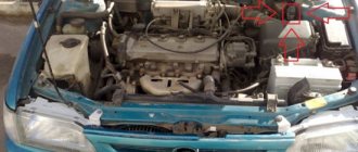
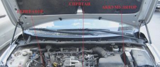
The connector for diagnosing the engine is located near the battery or on the left, along the direction of the car. Often this is a plastic box with the inscription “diagnostics” in English.
The Toyota Corolla diagnostic instrument panel is located in the driver's cab. The indicator itself on the display can be in the form of an engine, a spiral or a “check” icon. It depends on the year of manufacture and brand of engine, the icon itself is not so important, what matters is the fault codes.
If the automatic transmission is faulty, this will be known using “Power”, “AT Check”, “OD”. Faults in other units will be displayed through their corresponding light diodes.
Socket No. 2 for diagnosing engine malfunctions is located in the cabin, at the bottom of the panel, and this facilitates trouble-free determination of malfunctions while the Toyota Corolla is in motion.
READ MORE: Features of replacing the fuel filter of different modifications of Toyota Corolla
Most Common Error Codes
Toyota uses the following codes: single-digit and two-digit. Their decoding is presented in the following collection of information:
Fault detection algorithm:
- Under the hood in the “Diagnostic” box, bridge the two chips “E1” and “TE1”.
- Start the Toyota Corolla, turn on the air conditioner and heater and watch the indicators on the display.
- Frequent blinking (pause less than half a second) more than ten times is evidence of the absence of a recorded malfunction of this type in the memory. The engine will be safe to use. Open the contacts in the fault tester and you can carry out your planned trips.
- If the indicator blinks with long pauses (four and a half seconds), there is no need to worry too much: you are in for a minor maintenance-type repair.
- The following two types of signal: flashing - pause - flashing - long pause - flashing (fault code 21) or flashing - interval - flashing - long interval - flashing (code 12) indicate the presence of data of this kind in the computer memory and, most likely, you awaiting major renovations.
Here is a detailed video about self-diagnosis:
In order to make sure that the Toyota Corolla malfunctions are correctly diagnosed, double-check the results on the console inside the car, under the driver's seat. If the result is the same, check the table to see what type of malfunction your car has and decide on the method and place to fix the problem.