Designation of fuses and relays Funcargo 1999-2007.
Definition and purpose of fuses and relays for Toyota Funcargo from 1999 to 2007. Location and designation of fuses, relays in electronic systems of Toyota Funcargo cars manufactured from 1999 to 2007 with engines 1NZ-FE; 2NZ-FE. Which is very helpful in detecting faulty fuses and relays that are responsible for the electrical equipment of the car.
Blocks under the hood
Location
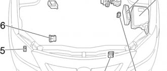
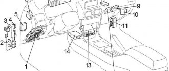
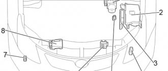
General layout of electrical control units under the hood
Left hand drive
Right hand drive
Designation
- Fuse and relay box
- without daytime running lights: relay box
- with daytime running lights: relay block No. 2
- Engine ECU
- Fuse block
- Glow plug relay
- Anti-skid control unit with drive
Fuse and relay box
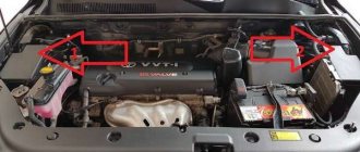
Located on the left side of the engine compartment.
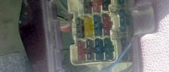
Photo - example
Example of a circuit from a block cover
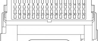
Scheme
Description
| 1 | — |
| 2 | 15A AM2 - Starting system, multiport fuel injection system / sequential multiport fuel injection system |
| 3 | 20A EFI - Multiport Fuel Injection System/Sequential Multiport Fuel Injection System |
| 10A HORN - 1NZ-FE, 2NZ-FE, 2SZ-FE, 2ZR-FE, 1KR-FE: Horn | |
| 30A ECD - 1ND-TV: Multiport fuel injection system/sequential multiport fuel injection system | |
| 4 | 10A HORN - 1KR-FE, 1ND-TV: Horn |
| 20A EFI - 1NZ-FE, 2NZ-FE, 2SZ-FE, 2ZR-FE, 1KR-FE: Multiport fuel injection system/sequential multiport fuel injection system | |
| 30A ECD - Diesel: Multiport fuel injection system/sequential multiport fuel injection system (TMMF, production since November 2008) | |
| 5 | Spare fuse |
| 6 | Spare fuse |
| 7 | Spare fuse |
| 8 | |
| 9 | |
| 10 | |
| 11 | 20A FR DEF — Heated front glass |
| 12 | 30A ABS2/VSC2 - Anti-lock braking system, vehicle stability control system |
| 13 | 30A H-LP MAIN - with DRL: “H – LP LH / H – LP LO LH”, “H – LP LH / H – LP LO LH”, “H – LP HI LH”, “H – LP HI RH” |
| 14 | 30A ST - Starting system |
| 15 | 20A S-LOCK - Steering Lock System |
| 16 | 15A DOME - Interior lighting, personal lighting, anti-theft system, audio system, wireless remote control system |
| 17 | 7.5A ECU-B - Engine Immobilizer System, Daytime Running Light System, Front Seat Occupant Classification System, Power Windows, Door Lock System, Anti-Theft System, Meter and Sensor |
| 18 | 7.5A ALT-S - Charging system |
| 19 | 10A ETCS - Multiport Fuel Injection System/Sequential Multiport Fuel Injection System, Electronic Throttle Control System |
| 20 | 10A HAZ - Direction indicators, hazard flashers |
| 21 | 50A AMT - Multi-Mode Manual Transmission |
| 40A BBC - Stop and Start System | |
| 22 | 10A H-LP RH - Right headlight |
| 23 | 10A H-LP LH - Left headlight |
| 24 | 10A EFI2 - Gasoline: Multiport fuel injection system/sequential multiport fuel injection system |
| 10A ECD2 - Diesel: Multiport fuel injection system / Sequential multiport fuel injection system | |
| 25 | 7.5A ECD3 - Diesel: Multiport fuel injection system/sequential multiport fuel injection system |
| 26 | 40A HTR SUB2 - 435W Type: PTC Heater |
| 50A HTR SUB1 - 600W Type: PTC Heater | |
| 27 | 50A EPS - Electric power steering |
| 28 | 50A ABS1/VSC1 - Anti-lock braking system, vehicle stability control system |
| 29 | 40A HTR - Air conditioning system |
| 30 | 30A RDI - Electric Cooling Fan |
| 31 | 30A HTR SUB1 - 435W Type: PTC Heater |
| 30A HTR SUB2 - 600W Type: PTC Heater | |
| 32 | 30A H-LP CLN //PWR HTR - Electric heater, headlight cleaner |
| 30A HTR SUB3 - 600W Type: PTC Heater | |
| Relay | |
| R1 | Starter (ST) - Starter |
| R2 | Electric cooling fan (FAN NO.2) - Cooling fan |
| R3 | PTC heater (HTR SUB1) – Heater |
Relay block
Scheme
Decoding
| 1 | — |
| 2 | — |
| 3 | 10A H-LP HI RH - Front right headlight |
| 4 | 10A H-LP HI LH - Front left headlight |
| Relay | |
| R1 | Dimmer (DIM) |
| R2 | Vehicle Stability Control / Anti-lock Braking System / Multi-Mode Manual Transmission (VSC1 / ABS1 / AMT) |
| R3 | — |
| R4 | Headlight (H-LP) |
| R5 | PTC heater (HTR SUB3) |
| R6 | PTC heater (HTR SUB2) |
| R7 | PTC heater (HTR SUB1) |
| R8 | Vehicle Stability Control/Anti-Lock Braking System (VSC2/ABS2) |
Additional relay block
Option 1
- R1 Vehicle Stability Control (VSC1)
- R2 Vehicle Stability Control (FR DEF / VSC2)
Electrical diagram of Toyota Funcargo:
Engine compartment fuse and relay box.
Location of the fuse and relay box in the engine compartment of the Funcargo.
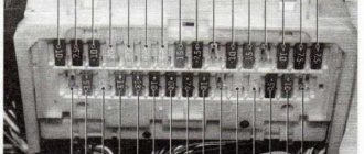
External view of the relay and fuse box of the engine compartment.
Relay and fuse diagram.
Relays and protect Funcargo are located in the engine compartment.
Fuse designation table.
Designation.
Rated current, A.
Purpose.
Warning system for keeping the ignition key in the lock and turning on the headlights when the engine is off.
Panel instrument cluster.
Headlights.
Interior lighting lamp.
Auxiliary system for rear view (on 2 wd models released from 08.2002).
Stability control system. Available on models from 08.2003 onwards.
Fuse block.
Designation.
Rated current, A.
Purpose.
Stability control system. Available on models from 08.2003 onwards.
Engine starting system.
Combination of instrument systems (Produced on models from 08.2002).
Headlights. (Models equipped with xenon headlights from 08.2002).
The relay block is located in the engine compartment.
Fuse designation table.
Designation.
Rated current, A.
Purpose.
Headlights (models equipped with xenon headlights produced from 08.2002).
About half a year ago I had to drain gasoline through the fuel pump. Gasoline barely flowed, and snorting and grunting could be heard in the area of the absorber. I opened the gas tank cap and gasoline poured out like a fountain. I didn’t attach much importance to this; I thought it was how it should be. Since this spring, when you start the engine, there has been a strong smell of gasoline, after a while the smell went away. Having crawled around and sniffed the car, I did not find any obvious gasoline leaks.
After reading articles on the Internet, I came to the conclusion that this problem is in the absorber.
But the conditions for checking the functionality of the absorber (fuel vapor accumulator), according to the manual, were observed:
A little theory.
Why do you need an adsorber in a car? The adsorber is the main element of the fuel vapor recovery system. The fuel vapor recovery system together with the adsorber prevents the emission of harmful substances into the atmosphere. The adsorber is filled with carbon, which absorbs gasoline vapors.
The overall diagram is valid for a car of any brand (in funcargo it’s a little different). The canister is usually located next to the fuel tank (under the hood in the funcargo) and is connected by pipelines to fuel vapor separators (there are no such in the funcargo) and to the canister purge valve located in the engine compartment. The solenoid valve for purge the adsorber is controlled by an electronic control unit (ECU). Fuel vapor from the tanks is partially condensed in the separator, the condensate is drained back into the tank through a pipeline (there is no such thing in funcargo). The remaining vapors pass through the pipeline into the adsorber through a gravity valve installed in the separator. The second fitting of the adsorber is connected by a hose to the adsorber purge valve, and the third is connected to the atmosphere. When the engine is not running, the second fitting is closed by a solenoid valve. When the engine starts, the engine control unit begins to send control pulses to the valve. The valve communicates the adsorber cavity with the atmosphere, and the sorbent is purged: gasoline vapors are discharged through the hose and throttle assembly into the intake module. Malfunctions of the fuel vapor recovery system lead to unstable idling, engine stalling, increased toxicity of exhaust gases and deterioration of the vehicle's driving performance. The components of the fuel vapor recovery system are removed for inspection or replacement when a persistent smell of gasoline appears due to a violation of the tightness of the components and pipelines, as well as as a result of a failure of the canister purge valve. In addition, failure of the adsorber seal and failure of the purge valve can cause unstable engine idling until it stops.
Or like this:
This system is designed to capture gasoline vapors in the fuel tank, throttle body and intake manifold, thereby preventing them from escaping into the atmosphere as hydrocarbons. The system consists of a tank with an absorber (activated carbon), pipelines connecting the absorber to the fuel tank, a thermal pneumatic valve and a control valve. When the engine is not running, gasoline vapors enter the absorber from the tank and throttle chamber, where they are absorbed. When the engine starts, the tank with the absorber is purged with a flow of air sucked in by the engine, the vapors are carried away by this flow and are burned in the combustion chamber. The tank is equipped with three ball valves assembled in a single housing. Depending on the operating mode of the engine and the pressure in the fuel tank, ball valves connect or disconnect the tank with a thermopneumatic valve (which is connected in series with the throttle valve chamber).
Normal operation of this device:
When the engine is turned off, this valve is closed, air with fuel vapor passes through the carbon filter and enters the atmosphere, while gasoline vapor accumulates in the coal. Then the engine starts. After some time (or upon reaching a certain speed - depending on the control program), this valve opens, and the engine begins to suck air through the absorber, ventilating it, taking gasoline vapors from the activated carbon, as well as remaining vapors from the fuel tank.
Abnormal operation of this device may occur as follows:
1st reason. The valve is not sealed, and the tube connecting the absorber to the atmosphere is clogged (a frequent phenomenon, given that the absorber itself is located in the wheel arch) (in a funcargo under the hood). Then, in the heat, gasoline vapors (and a lot of them can form in a half-empty tank) are poisoned through the valve into the intake manifold, clogging it and re-enriching the mixture in the first seconds of startup (until the entire intake manifold is pumped). This explains the failure to start the first or second time, the increasing number of cases of failure to start with an incomplete tank, the increasing number of cases of failure to start with gasoline that has a low boiling point.
Abnormal operation of this device can also manifest itself as follows:
2nd reason. The valve is sealed, and the tube connecting the absorber to the atmosphere is clogged. Then, after standing in the heat, gasoline vapors will accumulate in the fuel tank, increasing the pressure in it (when you unscrew the gas tank cap after parking in the heat, in this case you will hear pshshshh) (in funcargo there is a valve in the fuel tank cap that relieves excess pressure, so when unscrewing from this cap, air should not escape (basically, if the absorber is faulty, it is sucked into the gas tank), and if air escapes, it means that the valve in the gas tank cap is not working). When starting, as long as the valve is closed, everything happens normally. The car starts and runs for some time until the electronics think that the engine is already running quite steadily and it’s time to open the absorber valve. And at the moment the absorber valve opens, vapors under pressure rush from the gas tank into the air channel, clogging it and over-enriching the mixture. The engine stalls, but once started, it starts again as if nothing had happened (the pressure in the gas tank has been released, everything has returned to normal).
On more modern machines, error P0441 may be displayed. Well, then it brings along P0130, P1123, P0300, P0301, P0302, P0303, P0304, and all sorts of other errors regarding the operation of oxygen systems. The car jerks and stalls. Fuel consumption has increased.
Or it may be that due to a faulty absorber, a vacuum is created in the gas tank and under certain circumstances the gas tank may “collapse” (shrink), there are descriptions of such cases.
What to do if the absorber is faulty?
Buy a new one, expensive from 3500 to 7000 rubles. Delivery from 21 days and it’s not a fact that they will deliver. According to the catalog, it gives the number 77740-52041, but there is nothing for the original number 77704-52040.
Put it under contract, but the point is, it practically worked out what it was supposed to.
Try to disassemble the non-separable absorber and replace the insides.
I decided to try to take it apart. The danger of the event is that if you don’t “give some sense” to the disassembled absorber (that is, you don’t reassemble it later), the car won’t move. No, well, in principle, you can cut off the top cover where the valves are, connect it and drive like that. I haven’t tried to do this myself, but it should work :-).
To begin with (as usual) I “prepared”. I asked for advice, but no one really knows. I asked in the forum for silence, maybe they didn’t notice, or no one bothered, or “but the car drives, what else is needed”... I wanted to know in advance that it was funcargo inside the absorber. Maybe someone has one, it was broken, so they would know what material to prepare for replacement. This means no one has... I read it on the Internet, there are several notes that are similar to reports on the repair of the absorber.
Repair of the gasoline vapor accumulator absorber.
The absorber itself is in its place.
This is what it looks like.
With the top cover removed.
To disassemble it, you need to saw off the bottom of the absorber. But inside there are two springs, which on one side rest against the bottom of the absorber, and on the other against metal plates. Metal plates hold (compact) the coal inside. To prevent the coal from spilling, we first make cuts on the wide side, then secure these places with tape.
Then we file the remaining parts. We only saw along the edge with a depth of about 10 mm. There should be no through sawing, because the springs may be damaged.
They sawed it off. Turn it upside down and remove the tape.
We remove springs, plates, filters.
Pour out the coal.
Having read reports of “repairs” of such absorbers in other car brands, I expected that there would be foam intermediate filters.
As it turned out, the white gaskets in the photo, from now on I will call them intermediate filters, both upper and lower, between the coals are not foam rubber.
My opinion is that this is certainly the best option, because... Over time, the foam rubber turns into dust and clogs the absorber valves with this dust and coal; perhaps, in this case, this dirt can go further through the tubes.
We had to figure out what to make intermediate filters from. But more on that later.
Intermediate filters located in the upper part of the absorber are pressed into the absorber body. I had to cut them out and clean up the remains with a sharp chisel (nothing else could get around).
Fuses and relay blocks for Toyota Aygo (AB10) (2005-2014) with diagrams and descriptions
Fuse box diagram (fuse location), location and assignment of fuses and relays Toyota Aygo (AB10) (2005, 2006, 2007, 2008, 2009, 2010, 2011, 2012, 2013, 2014).
Checking and replacing fuses
The fuses operate before the entire wiring harness is damaged. If any of the electrical components do not work, a fuse may have blown. In this case, check and replace the fuses if necessary.
- Turn off the engine (using the smart key system - turn off the "ENGINE START STOP" switch) and turn off all electrical accessories.
- Open the fuse box cover.
- See the diagrams below to see which fuse to check.
- Remove the fuse.
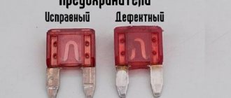
- Check to see if the fuse is blown - if the thin wire inside is broken, the fuse is blown.
- Replace the blown fuse with a new fuse of the correct rating.
Notification
- Never use a fuse with a higher amperage than specified, and do not use anything other than a fuse, even as a temporary measure. This may cause serious damage or even fire.
- Always use genuine Toyota fuses or equivalent.
- Do not modify fuses or fuse blocks.
- If the replaced fuse blows again, have it inspected by an authorized Toyota dealer or repair facility or other qualified and equipped person.
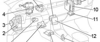
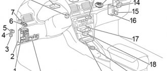
Passenger compartment
- Power steering ECU
- Central connector
- Multi-mode manual transmission ECU
- Power window relay
- LHD: Before February 2012: Tail light relay. From February 2012: rear fog lamp relay.
- Door control unit with receiver
- Relay block No. 1
- Air conditioner amplifier
- LHD: Fog light relay
- LHD: Running light relay
- Fuse box
- Airbag Sensor Assembly Center
- RHD: Relay block #2
- RHD: Before February 2012: Ignition Relay (IG) From February 2012: Power Window Relay
- RHD: Before February 2012: Power window relay From February 2012: Rear fog lamp relay
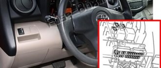
Interior fuse box diagram
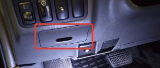
The fuses are located behind a cover on the instrument panel.
Remove the meter cover screws using a Phillips Head screwdriver. If the steering lock is on, please turn it off.
About fuses in funcargo – funcargo | diaries.ykt.ru
1. Relay block in the engine compartment
1. Location.
2. Top view. The fuses are numbered.
Explanation: 1. Main relay of the injection system 2. Relay of the electromagnetic clutch of the air conditioning compressor 3. Relay of the sound signal 4. Relay No. 1 of the fan motor 5. Relay No. 2 of the fan motor 6. Starter relay 7. Connector for connecting additional equipment (15A) 8 . H-LP RH/H-LP LO RH Headlights (halogen/xenon) (10A or 15A) 9. H-LP LH/H-LP LO LH Headlights (halogen/xenon) (10A or 15A) 10. ST (30A ) Starting system 11. AM2 (15A) Starting and ignition system 12. Horn (15A) Sound signal 13. EFI (15A) Engine management system Automatic transmission electronic control system (until 08.2002) Immobilizer system (from 08.2002) 14. Dome (15A) Central locking Warning system for the key left in the ignition and the lights not turned off Instrument cluster Audio system Clock Headlights (halogen) Interior lamps Rear view system (2WD models from 08.2003) 15. ABS No.1 (40A) Anti-lock braking system, traction control and system directional stability (models produced from 08.2003) 16. RDI (30A) Electric fan drive 17. Relay connector for connecting additional equipment.
3. Relay block back cover.
Mounting block under the instrument panel
1. Location.
2. Top view. The fuses are numbered.
Explanation: 1. Heater relay. 2. Main power relay. 3. Turn signal breaker relay. 4. Fuel pump relay. 5. AM1 (50A) I didn’t find a description, but I think it’s the Ignition and Starting Systems. 6. Power (30A) Electric windows, sunroof. 7. Heather (40A) Air conditioning with manual, automatic control. 8. Gauge (10A) Charging system (models produced before 08.2002). Engine control system. Automatic transmission electronic control system. Anti-lock braking system. Automatic transmission indicators. Electric windows. Central locking. Warning system for the key left in the ignition and the lighting not turned off. Seat belt warning system. Electric sunroof. Instrument cluster. Watch. Turn signals and hazard lights. Reversing lights. Air conditioning with manual and automatic control. Airbags (models produced from 08.2002). Anti-lock braking system, traction control and stability control (models released from 08.2003). 9. Def (20A) Rear window heater. 10. Door (25A) Central locking. 11. Tail (7.5A) Warning system for the key left in the ignition switch and the lighting not turned off. Instrument cluster. Watch. Headlights (halogen). Dimensions and lighting. Rear fog lights. Fog lights (until 08.2002). Air conditioning with manual control (until 08.2002). Headlights (xenon). 12. Wiper (20A) Cleaner and washer for windshield and rear windows. 13. Electronic B (7.5A) Engine control system. Automatic transmission electronic control system. Rear fog lights. Air conditioning with manual control (until 08.2002). Immobilizer system (from 08.2002). Anti-lock braking system, traction control and stability control (models released from 08.2003). Rear view system (2WD models from 08.2003). 14. Fog (15A) Fog lights. 15. Accessory (15A) Electric mirrors. Audio system. Cigarette lighter. Connector for connecting additional equipment. Rear view system (2WD models from 08.2003). 16. Electronic Ig (7.5A) Electric fan drive (until 08.2002). Anti-lock braking system. Interior lighting lamps. Air conditioning with manual and automatic control. Electric fan drive (since 08.2002). Rear window heater (from 08.2002). Anti-lock braking system, traction control and stability control (models released from 08.2003). Rear view system (2WD models from 08.2003). 17. Haz (10A) Turn signals and hazard lights. 18. A/C (7.5A) Air conditioning with manual and automatic control. 19. Invertor (15A) Connector for connecting additional equipment. 20. Stop (10A) Engine control system. Automatic transmission electronic control system. Anti-lock braking system. Stop lights. Anti-lock braking system, traction control and stability control (models released from 08.2003).
3. Relay block back cover.
