Installing the 1ZZ-FE cylinder head
Note:
— Before installation, thoroughly clean all parts.
— Before installation, lubricate all rubbing surfaces of the parts with new engine oil.
— Replace all gaskets and seals with new ones.
1. Install the cylinder head onto the cylinder block.
a) Install a new cylinder head gasket with the mark facing up.
b) Lower the cylinder head onto the gasket.
2. Tighten the head bolts
— The cylinder head bolts are tightened in two stages (b) and (d).
— If one of the bolts is damaged or not tightened to the specified torque, replace it.
a) Before installation, apply a thin layer of engine oil to the threads and under the bolt heads.
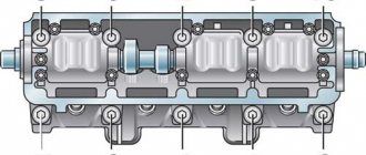
b) Using a 10mm hex wrench, install and evenly tighten the 10 cylinder head bolts with washers in stages in the sequence shown in the figure.
Tightening torque…………… 49 Nm
If one of the bolts does not tighten to the specified torque, replace it.
c) Mark the edge of the bolt facing the front of the engine (opposite power take-off side) as shown.
d) Tighten all bolts in the previous sequence by turning them 90°.
e) Make sure that all bolt marks are rotated 90° from their original position.
3. Connect the bypass refrigerant hose.
Torque …………………. 9 Nm
4. Install the camshafts a) Install the camshafts so that the valve cams of the first cylinder are as shown.
b) Install the camshaft bearing caps onto the corresponding main journals according to the numbers marked on them, as shown in the figure, with the arrows on the bearing caps facing the front of the engine (in the direction opposite the PTO - off).
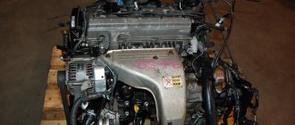
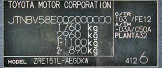
Technical characteristics of the Japanese engine
A new generation of engines replaced the “A” series in 1998.
In terms of technical characteristics, the Japanese engine is not particularly different; an important role was given to efficiency and environmental friendliness. Advantages of the 1zz engine: they installed a timing chain drive, thereby reducing the service life of the motor. The VVT-i system has improved low-end performance, increased specific power and torque, and reduced the actual weight of the engine.
Disadvantages of the 1zz engine:
- Repair of the 1zz engine is not carried out on many components, such as VVT-i and the chain with hydraulic tensioner;
- The chain is noisier than the belt;
- They increased the compression ratio to 10-10.5 or more, now you can’t fill a gasoline engine with “80”;
- Increased oil consumption due to waste, which is caused by design features;
- Maintainability. This is a disposable “motor”, because it is made of aluminum, with original repair pistons and you can forget about boring anything.
Description
Disconnect the negative terminal of the battery. We remove the ignition modules, the air filter with the housing. Drain the antifreeze and oil. Disconnect the fuel line.
Disconnect the injector connectors and remove the fuel rail. The O-rings will have to be replaced.
We disconnect all the pipes coming from the throttle assembly, unscrew the two nuts and three bolts for number 12 of the intake manifold.
We remove the manifold along with the throttle. We disconnect all electrics from the generator and starter, as well as from the air conditioning compressor and motor.
Good day to you! If you are reading this article, then you, like me, have been tormented by oil guzzling and chain rattle on the 1ZZ-FE.The compiler takes the liberty of adding the words Eugenio,77 if the oil decreases, it means either it is leaking or the engine is “eating” it. Oil burn is possible: a) through the crankcase ventilation system into the air filter or into the manifold - excess pressure in the crankcase - see piston, then see crankcase ventilation, in principle they are closely interconnected b) through oil seals (or a worn valve sleeve) - determined in the following way: warm up the engine, spin it smoothly (at least 4 thousand), sharply drop the gas and look into the exhaust pipe; if after these manipulations the smoke intensifies for a while, the caps are finished (the increased vacuum sucked the oil through them). the same thing - “traffic light test”: drive a warm engine, stop for a minute, then move off (more or less intensively) - if a gray cloud flies out at the start, and then everything is normal - it’s time for the caps to rest. c) through the rings - if it eats too much, if it starts to smoke when the speed increases, if the compression has dropped (and when pouring oil into the cylinder through the spark plug hole it increases - just don’t forget about possible “oil compression.” d) a crack in the block - without comments.
Let me make a reservation right away: I had no intention of doing a major overhaul of the engine, so I only changed the rings. I didn’t measure anything, didn’t look at the gaps, didn’t change the caps. I was just interested in checking the opinion that replacing the rings solves the oil problem. It was for this purpose that I got into the engine. Most likely, I will definitely miss something in my story, make a mistake somewhere, or call something differently from what it’s actually called. Don’t judge strictly, the material is large, and I’m not a professional, you can’t keep track of everything... Well, , let's get started?
Jack up the right front and remove the wheel. Then we unscrew everything from below that prevents us from getting to the engine crankcase (protection, plastic mudguards, etc.). The compiler had to order 2 pistons 90189-06013 because he still did not understand how they were removed. Neither and clips 90467-07164
Unscrew the drain plug and drain the oil. We drain the antifreeze from the block (there is a faucet on the back side, pictured below) and from the radiator (drain plug at the bottom left).
I wrapped 3 turns of electrical tape around the tube and poured it into a clean container. About 2.5 liters drained.
Unscrew the 2 screws and 2 plastic plugs securing the decorative cover and remove it.
Disconnect the 4 connectors from the spark plug coils.
Unscrew the 2 nuts securing the strip with wiring.
We unscrew the 4 bolts securing the coils and remove them. We turn out the candles.
Disconnect the ventilation hoses from the valve cover.
We unscrew the screws and nuts securing the valve cover, see if anything else is screwed on that is in the way - unscrew it. Remove ... Note from the compiler: in order to reduce the likelihood of any debris getting into the engine, it is advisable to remove the cover immediately before disassembling the engine.
I advise you to unscrew the PCV valve, wash it and evaluate the condition...
You can read about its operating system here
It's time to unscrew the bolt on the crankshaft pulley. Tighten it to your heart's content, prepare a good socket head and a long knob... Direction - counterclockwise. According to the book, a special device is used to unscrew it, which locks the pulley (pictured below).
Of course, there was nowhere to take it, so, remembering the experience of the same bolt on the G8, I simply stopped the flywheel at the junction of the engine and gearbox. Look below, there is a plastic cover there, remove it and insert something powerful between the teeth of the flywheel, like a large screwdriver. Make sure that it won’t jump out when rotating, get out from under the car and go try to unscrew the pulley. The first time it is unlikely that you will be able to secure the screwdriver so that it does not fall out... It is optimal, of course, to have an assistant...
Unscrew the bolt and remove the pulley. A key remains on the shaft, do not lose it. However, it sat firmly on me and clearly had no intention of falling out. We look around, assess the condition of the oil seal, whether oil is leaking from under it. If yes, well, you’ll have to change it. It's not difficult, the main thing is accuracy. When you put the pulley in place, wipe it from sand and dirt and lubricate the seat in contact with the oil seal in a circle with engine oil.
Now let's take care of the fuel rail, it also needs to be removed. Disconnect the connectors from the injectors...
Next, remove the black plastic part from the fuel line.
We pull it up, it snaps off. This will make it possible to rotate the fuel pipes relative to each other and move the ramp away from the work area. You can completely disconnect this connection and remove the ramp completely - I didn’t succeed, even with the help of a smart book...
We unscrew the fastening bolts, pull the ramp upward and remove it. (Again, in order to prevent dirt from entering the combustion chambers, it is advisable to clean the surface of the head near the injectors from dirt (with compressed air or a brush). It is impossible to predict where the injectors will remain, in the rail or in the head, but, most likely, in the ramp. It is quite likely that there is pressure in the ramp and splashing around gasoline cannot be avoided, prepare a rag or oilcloth and cover it when removing the ramp, at least you will protect yourself and the surrounding area from abundant spraying of gasoline
Don't forget to remove the 2 plastic bushings on which the ramp was attached
The injectors on the ramp will look like this
Pay attention to the rubber o-ring at the bottom of the injector. If it is not there, it is likely that it remains in the block head. There are 4 such rings, one per injector. The manual strictly states that all o-rings (and indeed almost all the rubber bands that are in the engine) should not be reused. I don’t know, I don’t know, all my rings turned out to be soft and, in my opinion, quite suitable for further use. Look at your own situation...
Immediately brief recommendations for assembly. The places under the lower sealing rings in the block head will most likely be covered in dust and dirt; everything needs to be carefully cleaned. Remove the rings from the injectors and carefully clean them of dirt/sand. We wipe the injectors themselves. Those who wish can wash them; there is material on this topic. Next, I would advise lubricating the lower rings with regular engine oil and immediately installing them in the cylinder head. We also lubricate the upper O-rings, put them on the injectors, lubricate them again on top and install the injectors in the ramp, as in the figure below. Then you will put the ramp assembled with the injectors in place, in the head, at the same time checking whether the injectors fall into the O-rings and adjusting the direction as necessary.
Next, remove the intake manifold. We unscrew the fasteners. Next, rely on your intuition, because... The throttle body is attached to the manifold on the right, and it is almost impossible to describe in detail every wire and hose that fits there. Just see what bothers you and disconnect.
The connectors are made according to the mind; you won’t be able to insert them into the wrong sockets. There is a gasket under the manifold; it cannot be reused (again according to the book). I installed a new one, fortunately it’s inexpensive.
Let's continue...
A good spanner wrench (breaking the edges is like nothing to do...) with an extension cord (because it’s hard...) slowly! squeeze the tensioner and remove the belt.
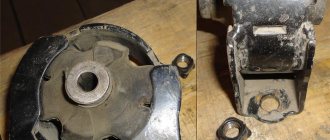
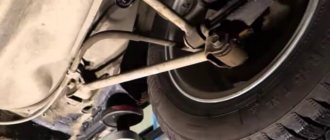
Unscrew and remove the right engine mount. Before this procedure, the engine from below must be slightly jacked up to avoid sagging due to removal of the support. I advise you to choose the location for installing the jack responsibly, so that the jack does not interfere with the removal of the oil pan, and there is an opportunity to further lift the engine to remove the screw securing the belt tensioner. More on this below...
We unscrew the nut (upper arrow) securing the tensioner and the bolt (lower arrow) on which the entire tensioner structure is attached to the block. Here you will need to jack up the engine, because the bolt is long and it will not be possible to remove it without jacking it up. Remove the tensioner assembly. We assess the condition of the bearing. There was almost no lubricant in mine, I had to correct this deficiency. Now it’s like new. We look carefully at the tensioner bushings; they may also need to be brought into perfect condition. More on this towards the end...
We unscrew the 3 bolts and remove what the right engine mount was attached to. In order to reduce the load on the remaining engine mounts when the chain cover was removed, I later returned this unit to its place, simulating the thickness of the cover with nuts of a suitable width.
Unscrew the 2 nuts and remove the hydraulic chain tensioner
We unscrew the 2 bolts and move the sensor to the side so that it does not interfere
Minus 6 bolts - and the pump is in our hands. Don't lose the o-ring. Think for yourself about the prospects for its further use. If anything - sealant is a good thing I don’t remember exactly, but 2 or 3 bolts are short
, compared to the others!
Be sure to note where they were and when assembling, put them only in their places! I don’t recommend screwing long bolts into short holes at all; you won’t tighten them completely and there is a very real chance of damaging the cover. Well, or the bolt will break, as happened to me... Pulling out the fragment is a different story... The compiler was too lazy to drain the antifreeze from the lower hole of the radiator, so when removing the pump, about 0.5 liters of antifreeze spilled onto the floor.
We unscrew the bolt securing the power steering pump pulley (we lock the pulley with a screwdriver in place) and two nuts securing the pump itself. There is no need to remove it at all, just leave it on the bolts.
We unscrew the 2 bolts securing the generator, pull it out of place and move it aside... In fact, it’s easier to remove the generator altogether. To do this, you need to unscrew the common wire and disconnect the connector that goes to it.
We unscrew the 3 bolts securing the compressor and, without connecting the hose, carefully attach it to the lower radiator hose.
We unscrew the remaining screws/nuts/studs around the perimeter of the cover and, using a screwdriver, pry it off and remove it. Pry gently, without scratching the surface too much
Remove the star at the bottom. During subsequent installation, be careful that the letter “F” on it should face you.
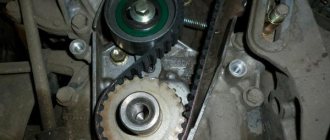
Unscrew the bolt and remove the left chain guide.
Using screwdrivers (or just your hands), we pull the lower gear towards ourselves. It is not necessary to remove it at all, the main thing is to pull it out to such a state that you can remove the chain. Pull it out and remove the chain.
Unscrew the 2 bolts and remove the right damper.
We unscrew the bolt and remove the valve that controls the oil supply to the VVT clutch. We assess the condition, wash and clean. I would like to note that it is very difficult to remove (at least for me), so be careful. Do not try to pull on the connector, it will easily break.
A little lower, under the valve, you can unscrew the bolt and remove the filter through which the oil enters the clutch. The recommendations are the same, wash, clean, depending on the situation...
We unscrew the bolts of the camshaft covers in the indicated order and remove the covers and shafts.
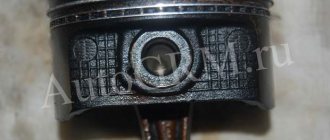
Treat this procedure carefully; each cover will subsequently need to be placed in the place where it was and oriented in a certain direction. It is best to place them somewhere to the side in the exact order in which they were on the engine. Under the shafts you will find valve adjusting cups, 16 in total. We take it out and lay it out so that later we don’t confuse which valve is which cup.
The compiler, having measuring probes, determined the gaps between the pushers and valves. With a mileage of 105,000 km, the clearances were normal: Intake 0.2 0.2 0.2 0.2 0.2 0.2 0.15 0.2 (normal 0.15-0.25) Exhaust all 0.3 (norm 0.25-0.35).
We unscrew the 10 bolts securing the block head in the indicated sequence. Here you will need a good tool, because... The bolts are tightly tightened. Since these bolts will have to be tightened “well”, I purchased a large torque wrench. Its lever is enough to unscrew the bolts.
If according to science, then you need the so-called “10 mm bi-hexagon wrench”, in reality it turned out to be an ordinary internal sprocket, in the photo there is a bolt head and a wrench for it:
Since I didn’t have this key in stock, there was nowhere to look/buy, and the importance of the tightening operation was beyond doubt, a knight’s move was made, and along with other junk required during this operation, a special one was ordered and purchased Toyota key is just for this purpose. Here it is:
Did you unscrew the screws? Wonderful, there’s just a little bit left. Just a little bit left until the disassembly operation is over...
Now is the time to work under the car. You need to unscrew the 2 bolts securing the exhaust pipe to the exhaust manifold.
and 3 bolts securing the exhaust manifold bracket. You can remove the cylinder head with it, but installing it without it is much easier.
Then you need to unscrew the fasteners around the perimeter of the engine pan and remove it. It is difficult to do this procedure without a razor or knife. Immediately remove the oil filter, change it anyway...
Unscrew the 2 nuts and bolt from below and remove the oil intake. There is a gasket underneath, don't lose it. We assess the cloggedness of the mesh, wash...
Well, actually, based on disassembly, that’s all. You can try to pull off the block head... Let's look carefully again to see if everything is disconnected from it and if nothing is in the way; if we find something, turn it off. The head is relatively not heavy, I removed it alone and did not experience any particular inconvenience in terms of its weight. If you doubt yourself, call an assistant...