Background
A long time ago, in a distant galaxy, one of our regular clients decided to buy an SUV, but since he had a limited budget, he hesitated between an almost new Chevrolet Niva and an older RAV4.
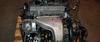
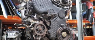
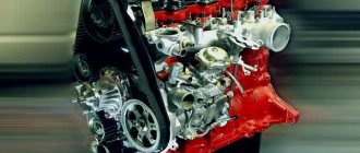
And then, finally, it happened. A 2001 RAV4 came to us with a 1ZZ-FE 1.8 liter engine and a heart-warming story about the happy new owner. Since the car was bought in a neighboring region, at a local service station they lifted it up on a lift, measured the compression, which turned out to be 11 in all pots, and after giving an excellent rating, they let us go on our way. But it was not there! On the way home, it turned out that the car was eating oil in buckets. The reason lies in a factory defect. On 1ZZ-FE engines until 2004, there were only two drainage holes in the groove of the piston oil scraper ring; after a mileage of 140,000, they coked and the rings stuck. Later, four holes were made in the piston on each side, which solved the problem. Therefore, there is only one way out: we replace the old pistons with new-style pistons, as well as rings and connecting rod bearings. Piston kit 13101-22180. There is a good write-up on the selection of spare parts in this article. By the way, the previous owner aggravated this situation by pouring the birthmark oil L... (well, you get the idea) - you have to dislike the Japanese so much.
Description
Disconnect the negative terminal of the battery. We remove the ignition modules, the air filter with the housing. Drain the antifreeze and oil. Disconnect the fuel line.
Disconnect the injector connectors and remove the fuel rail. The O-rings will have to be replaced.
We disconnect all the pipes coming from the throttle assembly, unscrew the two nuts and three bolts for number 12 of the intake manifold.
We remove the manifold along with the throttle. We disconnect all electrics from the generator and starter, as well as from the air conditioning compressor and motor.
We also remove everything from the side of the box and remove the wiring harness so that it does not interfere.
We remove the generator, pump, front timing chain cover and the chain itself with stars. Read more in the article about replacing the chain on the 1ZZ-FE engine.
Disconnect the exhaust pipe from the exhaust manifold.
In several passes, we first loosen and then unscrew the 19 bolts of the camshaft bearing caps, always in the specified sequence.
Remove the bearing caps and carefully place them in the same way as they were removed.
We remove the camshafts. The intake valve shaft is longer.
In the same way, in several passes we loosen and unscrew the 10 bolts securing the cylinder head. Must be in the specified order. By neglecting the last rule, you risk at least taking the head for grinding, and at most purchasing another one.
We remove the bolts and washers, and also mark and remove the valve tappets. We remove the cylinder head.
And an old gasket.
We unscrew a lot of bolts and two nuts of the oil pan and remove it. It's on sealant, so you'll have to tinker.
We unscrew two bolts of each connecting rod cover and carefully remove it by loosening it. The insert should remain in the lid. If not, remove them from the crankshaft and put them back into the cover. We mark which cylinder each cap comes from. Don't get confused. The front of the bearing cap is marked with ebb.
We push the pistons with connecting rods up.
We see stuck oil scraper rings.
The rings were so coked that I had to pick them out with a knife; the drainage holes were clogged tightly.
While we are dealing with the piston, in the next box, specialist Seryoga is working magic on the head. Having measured the plane, we are pleased with the fact that there is no need to give it for grinding.
But what happened to the valves and channels. No comments here.
Release.
Inlet.
valves.
Well, how can I, the youngest person, clean all this, but they say we have a democracy. I cleaned it, Seryoga changed the valve seals. It was getting dark.
Having received the assembled cylinder head, I went to assemble the engine. Well, everything here is like in the book.
If the connecting rod bearings are scuffed, replace them.
We will not grind the crankshaft, since the client is already over budget. For the money that a full capital costs, you can bring in a 2005 contract truck. There is a marking on the liners on the reverse side, which is why we order new ones.
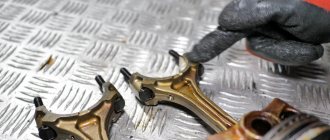
We knock out the finger from the old piston, having first picked out the retaining ring. We mark the front of the connecting rod, as well as the cylinder number.
We are collecting a new one.
We install a retaining ring on one side of the piston.
Align the front marks on the piston and connecting rod. Lubricate the new piston pin with engine oil and, using the thumb of your right hand, press the piston pin into place.
We install the second retaining ring. In the same way, all four.
We check the gaps in the new piston rings. We insert the rings one by one into the cylinder where they will subsequently work.
We push the piston to a depth of 110 mm.
We measure the gap.
The minimum clearance for the first compression valve is 0.25 mm, for the second one - 0.35 and for oil scraper valves - 0.15 mm. If you have less you will have to sharpen it. Maximum 1.05 1.2 and 1.05 mm respectively.
Some rings have marks, they should face up. We put everything in its place, the first compression, the second, two oil scrapers and an expander.
Degrease the adjacent surfaces of the connecting rod and liner. We put new liners into the connecting rod and the cover. We do not lubricate with oil and make sure that nothing gets under the liners.
We unfold the rings with locks as shown schematically in the photo.
1 – lock of the first compression ring
2 – lock of the lower scraper of the oil scraper ring
3 — lock of the second compression ring
4 - lock of the upper scraper of the oil scraper ring
Lubricate the ring mandrel with clean oil, compress the rings and place the piston in the cylinder. Don't forget about the "before" mark.
Use the wooden handle of a hammer to push the piston. Lubricate the crankshaft journals and bearings with clean oil. Replace the connecting rod bearing caps. Don't confuse numbers and directions. Tighten the bolts by hand. We tighten all the bolts to a torque of 20 N*m, after which we turn it another 90 degrees. We turn the crankshaft; it should rotate easily without jamming. We put the oil pan and a new head gasket in place.
We clean all the head bolts, as well as the holes in the block from oil and dirt. We put the cylinder head in place. We tighten the bolts in several passes, in a certain sequence with a torque of 49 N*m and turn them 90 degrees.
We put the valve pushers in place. Lubricate everything with oil.
Camshafts, the key on the front side should face up.
We install the camshaft bearing caps in accordance with the direction and number. Inlet I2 I3 I4 I5 and exhaust E2 E3 E4 E5. The arrow indicates the "front" direction.
Tighten the bolts evenly in the specified sequence. After preliminary tightening of bolts No. 9, we tighten all the others in several passes. The tightening torque of bolts No. 9 is 23 N*m, the rest – 13 N*m.
Next, we install the timing drive, as described in the previous article. Fill with good new oil and antifreeze. To remove the air lock, you can remove the heater hoses one by one, they are right at the very top. After final assembly, without connecting the injector connectors, crank the engine with the starter, several approaches for about five seconds. We connect the injectors and, pressing the clutch, start it. Before I started, the spark plugs flooded twice. After it starts, let it idle, turn it off, check the antifreeze, and top it up. And so on several times. After the air lock has been eliminated, warm it up until the cooling fan comes on and turn it off. Let it cool, check the antifreeze and repeat two or three more times. After that you can drive, but only for the first 200 - 300 km we take care of the engine, we try not to let it exceed 3000 revolutions and the main thing is not to overheat. Further is optional, but it’s better to roll out the first thousand calmly.
Cylinder head tightening torque on ZMZ engines.
ZMZ engines are represented by modifications ZMZ-402.5, ZMZ-402.6, ZMZ-4061, ZMZ-4063, ZMZ-40522, ZMZ-40524. The cylinder head tightening torques for these engine models have different values.
Tightening torque of the cylinder head (cylinder head) on 402 engines (GAZELLE), modifications of ZMZ-4025,4026 engines.
| Detail | Thread | Tightening torque, Nm (kgf*m) |
| Cylinder head nut | — | 85-90 (8,5-9) |
| Rear cylinder head cover bolt | — | 11-16 (1,1-1,6) |
| Cylinder head cover bolt | — | 4,5-8 (0,45-0,8) |
Table No. 10. Tightening torque of the cylinder head (cylinder head) of ZMZ 4025 and ZMZ-4026. Tightening torque of the cylinder head (cylinder head) on 406 engines, modifications ZMZ-4061, ZMZ-4063, ZMZ-40522.
| Detail | Thread | Tightening torque, Nm (kgf*m) |
| Cylinder head bolt | — | 1) Pre-tightening: 69-82(6.9-8.2); 2) Hold for at least 1 minute 15 seconds - and final tightening - Turn to an angle of 70-75 degrees. |
Table No. 11. Tightening torque of the cylinder head (cylinder head) ZMZ-4061, ZMZ-4063, ZMZ-40522. Tightening torque of the cylinder head (cylinder head) on 405 and 405 Euro3 engines, modification ZMZ-40524.
| Detail | Thread | Tightening torque, Nm (kgf*m) |
| Cylinder head bolt | — | 1) Pre-tightening: 40-50(4.0-5.0); 2) Hold for at least 1 minute 15 seconds - and final tightening - Turn to an angle of 90 degrees. |
Table No. 12. Tightening torque of the cylinder head (cylinder head) ZMZ-40524. Tightening torque of the cylinder head (cylinder head) on ZMZ-409 engines.
| Detail | Thread | Tightening torque, Nm (kgf*m) |
| Cylinder head bolt | — | 1) Pre-tightening: 40-60(4.0-6.0); 2) final tightening: 130-145 (13.0-14.5) |
Table No. 13. Tightening torque of the cylinder head (cylinder head) ZMZ-409.
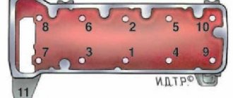
The sequence of tightening the cylinder head bolts is shown in the figure.
Tightening torque for GAZ-53 cylinder head.
| Detail | Thread | Tightening torque, Nm (kgf*m) |
| Cylinder head nuts | — | 77-82 |
Table No. 14.
Tightening torque of the cylinder head (cylinder head) of GAZ-53. Tightening torque of the KAMAZ-740 cylinder head The tightening torque on the KAMAZ-740.10, KAMAZ-7403.10 or KAMAZ-740.11-240 engines is the same and is shown in table No. 15.
| Detail | Thread | Tightening torque, Nm (kgf*m) |
| Cylinder head bolts | M16 | 157 — 176 (16 — 18) |
Table No. 15.
Tightening torque of the cylinder head (cylinder head) of KAMAZ-740. There are no similar entries.