The fuses installed in the Toyota Camry 40 serve to protect the vehicle’s on-board network from short circuits and long-term overloads. Burnout of the jumper leads to disconnection of the circuit. The consequences of this may vary depending on which equipment is de-energized.
The failure of a fuse can make further driving of the car impossible, but in most cases the systems that provide the comfort of using the car, for example, heated seats or power to the cigarette lighter, are de-energized.
Frequently blown fuses can be a warning sign for a car owner. For example, damage to the insulation and breakdown on the body is possible. It is prohibited to thoughtlessly change jumpers without identifying the cause of their damage, as this may subsequently lead to a car fire.
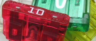
Burnt and good fuse
Fuse box locations
In the Toyota Camry 40 there are two places where the fuses are located:
- inside the car;
- in the engine compartment.
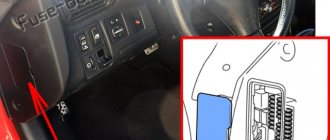
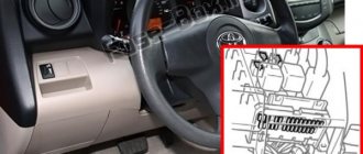
In the cabin, the fuse box is located to the left of the steering rack. Not far from it is the hood release lever. The images below show the location of the interior unit in the 2007 Camry 40.
Location of the interior fuse box
Interior fuse box with cover
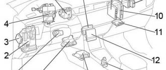
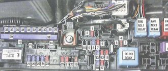
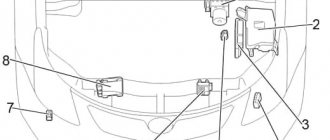
In the engine compartment, the mounting block is located next to the air filter, battery and brake fluid reservoir. In the figure below, the fuse and relay block is indicated by number 7.
Location of the mounting block in the engine compartment
The fuses are located inside the plastic housing. To gain access to them you need to remove the cover.
Mounting block housing
Blocks in the interior of Toyota Camry 40
Layout diagram
Designation
- Fuse box
- Body electrical control unit
- Turn signal relay (hazard warning lights)
- Distribution block No. 3
- ID unit (vehicles with Smart System) Key transponder (vehicles without Smart System)
- Distribution block (CAN)
- Distribution block No. 4
- Air conditioner amplifier
- Certification block
- Tire pressure monitoring unit
- Airbag central unit
- Audio amplifier
- Gearbox selector lock block
- Key signal amplifier
- Steering lock block
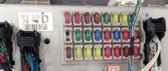
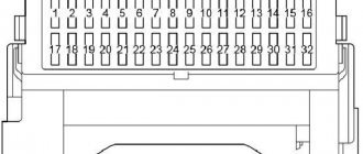
Fuse box
Installed on the left under the instrument panel. To gain access, you must remove the protective cover.
Scheme from the block cover
Scheme
Description
| 1 | 25A RR DOOR RH Rear right window lift |
| 2 | 25A RR DOOR LH Rear left window lift |
| 3 | 7.5A FUEL OPN Fuel filler flap |
| 4 | 15A FR FOG Front fog light |
| 5 | 7.5A OBD Diagnostic Connector |
| 6 | 7.5A ECU−B NO.2 Glass lifts |
| 7 | 10A STOP Brake lamps, auxiliary brake lamp, shift lock, fuel injection system, body control module, ABS, vehicle stability control, traction control, brake assist, throttle control |
| 8 | 30A TI&TE Tilt and Telescopic Steering |
| Reserve | |
| 9 | 7.5A AM1 Fuel injection system |
| 10 | 7.5A A/C Air Conditioning |
| 11 | 25A PWR Glass Lifters |
| 12 | 25A DOOR NO.2 Body electrical control unit |
| 13 | 30A S/ROOF Hatch |
| 14 | 15A TAIL Side lights, license plate lights, reversing lights, front turn signals, body control unit |
| 15 | 7.5A PANEL Navigation, heated seats, hazard lights, air conditioning, audio system, clock, glove box lights, vehicle stability control, traction control, instrument panel lights, steering wheel switches |
| 16 | 10A ECU IG NO.1 Body Electrical Control Unit, Wiper & Washer, Sunroof, Tire Pressure Monitoring System, Cooling Fan, Navigation, Auto Dimming Interior Mirror |
| 17 | 7.5A ECU IG NO.2 ABS, Vehicle Stability Control, Traction Control, Brake Assist, Shift Lock, Automatic Transmission, Cruise Control |
| 18 | 10A A/C NO.2 Air conditioning, heated rear window |
| 19 | 10A WASH Windshield wiper and washer |
| 20 | 20A S-HTR Heated seats |
| 21 | 10A GAUGE NO.1 Hazard warning lights, reversing lamps, fuel injection system, battery charging system |
| 22 | 25A WIP Wiper and washer |
| 23 | 7.5A H−LP LVL Electric headlight range control |
| 24 | 15A INJ Fuel injection system, starting system |
| 25 | 10A IGN Fuel Injection System, Anti-Theft System, Airbags, Steering Lock System, Front Passenger Classification System, Throttle Control System, Keyless Entry System |
| 26 | 7.5A GAUGE NO.2 Instrument cluster, clock, multi-information display |
| 27 | 7.5A ECU-ACC Clock, Shift Lock, Body Electrical Control Module, Power Mirrors, Keyless Entry System |
| 28 | 20A CIG Cigarette Lighter |
| 29 | 20A PWR OUTLET |
| 30 | 7.5A RADIO NO.2 Audio system, navigation |
| 31 | 10A MIR HTR Heated mirrors |
The cigarette lighter and rear socket are protected by fuses 28 and 29 at 20A.
Fuses 32 for 30A POWER Window regulators and 33 for 30A P/SEAT Electric seats are located separately on the top of the unit.
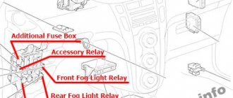
Relay
Several relay elements are attached to the back of the block.
Scheme
Purpose
- R1 Fog light
- R2 Side light
- R3 Auxiliary relay
- R4 Window lifters
- R5 Ignition (IG1)
The purpose of the fuses of the Toyota Camry 40 car and the diagram of their placement in the blocks
The location of fuses in the interior mounting block is shown in the figure below.
Interior mounting block
The assignment of fuses in accordance with the numbers shown in the figure above is shown in the table below.
Table - Purpose, color and rated current of interior unit fuses
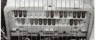
The mounting block, located in the engine compartment, contains a relay in addition to fuses.
Relays and fuses in the mounting block located in the engine compartment
A description of the purpose of the fuses located in the engine compartment of the Toyota Camry 40 is given in the table below.
Table - Purpose, rated current and color of elements of the mounting block located in the engine compartment
Fuses and relays Toyota Camry XV50, 55 in the engine compartment
Take a look at the photo. It is on the left side as the vehicle moves that the fuse box is located. Right next to the left wing.
The blog is protected from dust and moisture by a cover that can be easily removed by pressing the latch on the front.
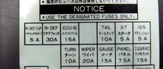
On the back of the cover you can find clues as to which fuse is responsible for what. If you are not strong in English or for some reason you cannot understand or look at this cover, then the following is about the location of the fuses in this block and their decoding.
| Melting fuse | Denomination | Chain | |
| 1 | METER-IG2 | 5 A | Measuring instruments |
| 2 | FAN*1 | 50 A | Electric cooling fans |
| 3 | H-LP CLN | 30 A | Headlight cleaner |
| 4 | HTR | 50 A | Air conditioning system |
| 5 | ALT | 120 A*2 | Battery charging system |
| 140 A*3 | |||
| 6 | ABS No.2 | 30 A | Vehicle stability control system |
| 7 | ST/AM2 | 30 A | Starter system. ECU-IG2 N0.1, A/B. ECU-IG2 N0.2 |
| 8 | H-LP-MAIN | 30 A | H-LP LH-LO. H-LP RH-LO. headlights (low beam) |
| 9 | ABS N0.1 | 50 A | Vehicle stability control system |
| 10 | EPS | 80 A | Electric steering |
| 11 | S-HORN | 7.5 A | S-HORN |
| 12 | HORN | 10 A | Sound signal |
| 13 | EFI #2 | 15 A | Multiport fuel injection system/sequential multiport fuel injection system, electronically controlled transmission |
| 14 | EFI #3 | 10A*1 | Multiport fuel injection system/sequential multiport fuel injection system |
| 7.5A*4 | |||
| 15 | INJ | 7.5 A | Multiport fuel injection system/sequential multiport fuel injection system |
| 16 | ECU-IG2 No. 3 | 7.5 A | Multiport fuel injection system/sequential multiport fuel injection system, steering column lock system, electronically controlled transmission |
| 17 | IGN | 15 A | Starter system |
| 18 | D/L-AM2 | 20 A | All door locking system |
| 19 | IG2-MAIN | 25 A | IGN. INJ,METER-IG2. ECU-IG2 N0.3, A/B, ECU-IG2 N0.2. ECU-IG2 N0.1 |
| 20 | ALT-S | 7.5 A | Battery charging system |
| 21 | MAYDAY | 5 A | No scheme |
| 22 | TURN&HAZ | 15 A | Direction indicators, hazard warning lights, measuring instruments |
| 23 | STRGLOCK | 10 A | Steering Column Lock System |
| 24 | AMP | 15 A | Audio system |
| 25 | H-LP LH-LO | 15A*5 | Left headlight (low beam), system |
| 20 A*6 | manual headlight level adjustment | ||
| 26 | H-LP RH-LO | 15A*5 | Right headlight (low beam). |
| 20 A*6 | manual headlight leveling system | ||
| 27 | MNL H-LP LVL*7 | 7.5 A | No scheme |
| 28 | EFI-MAIN N0.1 | 30 A | Multiport fuel injection system/sequential multiport fuel injection system. EFI N0.2, EFI N0.3, A/F sensor |
| 29 | SMART | 5 A | Intelligent keyless entry system |
| 30 | ETCS | 10 A | Electronic throttle control |
| 31 | TOWING | 20 A | No scheme |
| 32 | EFI N0.1 | 7.5 A | Multiport fuel injection system/sequential multiport fuel injection system, electronically controlled transmission |
| A/F*1 | A/F Sensor, Multiport Fuel Injection System/Sequential Multiport Fuel Injection System | ||
| 33 | EFI-MAIN No.2*4 | 20 A | |
| 34 | AM2 | 7.5 A | Intelligent keyless entry system |
| 35 | RADIO-B | 20 A | Audio system, navigation system |
| 36 | DOME | 7.5 A | Clock, mirror lights, interior lights, reading lights, trunk lights, door step lights |
| 37 | ECU-B N0.1 | 10 A | Multiplex communication system, intelligent keyless entry system, instrumentation, steering column tilt and height adjustment system, steering wheel sensor, remote control |
It remains to be said that depending on the configuration (engine, etc.) there may be different fuse ratings.
*1 — 2GR-FE engine;*2 — Vehicles without rear seat heater;*3 — Vehicles with rear seat heating;*4 — 2AR-FE engines;*5 — Vehicles with halogen headlights;*6 — Vehicles with HID headlights; *7 - not available in all trim levels;
Now about the fuses in the car interior.
Replacing the steering cable
This breakdown is the most difficult. Restoring the loop is physically impossible. To buy a new one, you will have to pay from a thousand rubles for a non-original, and up to 4.5 thousand for a licensed version. Professionals advise saving money and installing a cheaper cable. The fact is that in this rather rare case, both samples of the cable are not an important part, they break extremely rarely and are practically no different from each other. And if there is no difference, why pay more?
First of all, do not forget to remove the terminals from the battery. Otherwise, smart electronics will consider that it is time for the airbag to deploy.
Unscrew the airbag and then the nut that secures the steering wheel to the shaft. After you remove the steering wheel, you will be able to see the cable, which needs to be replaced with a new one. Everything is going the other way around. First, the nut that holds the steering wheel to the shaft is screwed on, and then the airbag is screwed on. When assembling, please note that when replacing the cable, you need to put the wheels straight so that the cable does not break again in the future.
Purpose of fuses
Fuses are designed to protect electrical and electronic components from short circuits and overloads. If the insulation is damaged or elements fail, the current in the circuit increases.
This leads to heating of the parts. The protective insert has a jumper made of low-melting metal, which breaks if the current increases. To determine the fuse rating, plastic housings of different colors are used. The operating parameters are painted on the end part of the casing.
Fuse replacement process
Voltage drops occur in any electrical circuit, including automotive networks. The main function of a fuse is to disconnect the circuit when a short circuit occurs. This disconnection occurs due to the burnout of the conductor. A blown fuse must be replaced. How to do this, read on.
Fuse replacement pliers
Before starting the replacement process, it is necessary to find out the reason why the jumper failed. To do this, contact a qualified automotive electrician. You should not neglect this advice, since we are talking about the electrical network - and this is already a matter of safe operation of the vehicle.
After identifying the causes of the breakdown, proceed directly to replacing the fuse link. Initially, turn off all electrical devices and the ignition. Then open the engine compartment, remove the terminal with the “-” sign from the battery. Determine which Toyota Camry XV40 fuse box you need (to do this, use the diagrams and decodings). In the cover of the engine compartment block you will find spare fusible links and a special tool for working with them - tongs (use of needle-nose pliers is allowed).
Spare fuses and replacement pliers on the inside of the block cover
Next, you need to use pliers to remove the safety element corresponding to the diagram. When removing the fuse, try not to wobble, twist or unscrew it, as such actions will cause the socket to fail, where the fuse element will not be firmly fixed. This causes sparking and causes instability in current transmission.
After the electrical fuse is removed from the socket, check it: the conductor in the faulty element is broken. Install the new jumper, making sure you are using the correct rated insert.
Important nuances
Spare elements and tweezers are stored on the inside of the covers of the mounting boxes. It is recommended to carry a set of protective fuses with the ratings used in the electrical system of the Toyota Camry XV40. If the kit does not contain a part with the required parameters, then a temporary installation of a fuse designed for a lower current is allowed (for example, instead of 25 A - a 20 A element).
Manipulations related to the vehicle's electrical system are carried out with the ignition off.
The key must be in the driver's pocket, since the door locks may be blocked. If the installed fuse burns out when you try to turn on the circuit, you should take the car to a service center to diagnose the power systems and control units.
The nuances of using the cigarette lighter and sockets
Often a cigarette lighter is used to power gadgets, but to properly operate the device without damaging the car’s electrical network, a number of nuances must be taken into account.
If you wish to use outlets and power strips powered by the cigarette lighter, ensure that the maximum total load supported does not exceed the load capacity of the cigarette lighter circuit. The Camry XV40 cigarette lighter fuse is designed for a maximum current of 20A. This indicator must be taken into account when choosing a splitter.
The fuse is intact
If your cigarette lighter plug is constantly burning in your Toyota Camry 40 2006-2011, urgently contact a professional technician specializing in automotive electronics. This will allow you to detect the malfunction in time and eliminate it before the malfunction causes a fire.