Draw your attention to! The prices given in the table below are for informational purposes only and may change in one direction or another, depending on the complexity of repairing each specific steering rack, and are determined based on diagnostic results.
| car brand | Steering rack repair*, rub. | Removal/installation, rub. | Camber adjustment**, rub. | Toe adjustment price, rub. |
| Toyota 4 Runner 2002 | 6500 | 7200 | 2100 | 1700 |
| Toyota Auris | 4500 | 5700 | 1700 | 1500 |
| Toyota Avensis (T25) manual | 5500 | 5700 | 2100 | 1500 |
| Toyota Avensis (T25) hydraulic | 7000 | 6200 | 2100 | 1500 |
| Toyota Avensis (ZRT27b ADT27) | 6000 | 6200 | 2100 | 1500 |
| Toyota Avensis Verso (AC) | 6000 | 6200 | 2100 | 1500 |
| Toyota Aygo | 4500 | 5700 | 2100 | 1500 |
| Toyota Camry IV | 6500 | 6200 | 2100 | 1500 |
| Toyota Camry V (ACV40,GSV40) | 7000 | 6200 | 2100 | 1500 |
| Toyota Camry VI (ACV51,GSV50) | 7000 | 6200 | 2100 | 1500 |
| Toyota Carina E (T19) | 5800 | 5700 | 2100 | 1500 |
| Toyota Celica (ZZT23) | 6000 | 5700 | 2100 | 1500 |
| Toyota Corolla III (E11) | 5500 | 5700 | 2100 | 1500 |
| Toyota Corolla IV (120) | 6000 | 5700 | 2100 | 1500 |
| Toyota Corolla V (150) | 4500 | 5700 | 2100 | 1500 |
| Toyota Corolla Verso (ZER_,ZZE_) | 4500 | 5700 | 2100 | 1500 |
| Toyota HI ACE (H1, H2) | 7000 | 6700 | 2100 | 1700 |
| Toyota Highlander (MCU2, ACU2) | 7500 | 6700 | 2400 | 1700 |
| Toyota Highlander II | 7500 | 6700 | 2400 | 1700 |
| Toyota Hilux | 7500 | 6700 | 2100 | 1700 |
| Toyota Land Cruiser 100(J10) | 8500 | 7700 | 2100 | 1700 |
| Toyota Land Cruiser 150(J15)/Prado (J15) | 9000 | 7700 | 2100 | 1700 |
| Toyota Land Cruiser 200(J20) | 10500 | 12200 | 2100 | 1700 |
| Toyota Land Cruiser 90(J9)/ Prado(J9) | 8000 | 7200 | 2100 | 1700 |
| Toyota Picnic II | 5800 | 6200 | 1700 | 1500 |
| Toyota RAV 4 I(SXA1) 1994-… | 7000 | 8200 | 2800 | 1700 |
| Toyota RAV 4 II(XA2) 2001-… | 6500 | 8200 | 2800 | 1700 |
| Toyota RAV 4 III(ACA,ACE) 2005-… | 5000 | 8200 | 2800 | 1700 |
| Toyota Sequoia | 6500 | 8200 | 2900 | 1700 |
| Toyota Sienna II | 6000 | 6200 | 2100 | 1700 |
| Toyota Tacoma | 6000 | 6200 | 2100 | 1700 |
| Toyota Tundra | 7000 | 7700 | 2900 | 1700 |
| Toyota Venza | 4500 | 5700 | 2100 | 1500 |
| Toyota Verso | 4500 | 5700 | 1700 | 1500 |
| Toyota Yaris (CP10,NC /LP2) manual | 4500 | 5200 | 1700 | 1500 |
| Toyota Yaris (CP10,NC /LP2) hydraulic | 6000 | 5700 | 1700 | 1500 |
| Toyota Yaris 2006-… | 5000 | 5700 | 1700 | 1500 |
| Toyota Yaris 2011-… | 5000 | 5700 | 1700 | 1500 |
*The cost of steering rack repair includes:
- primary diagnosis
- fault detection
- replacing all seals
- repressing the piston on the main shaft (if required by the design feature)
- replacing teflon rings
- replacing rubber seals
- grinding (if there are fragments of corrosion on the shafts)
- final check on a hydraulic stand
In case of non-repairability of the main shaft (unremovable corrosion, missing teeth), distributor gear (unremovable corrosion, missing teeth), deterioration inside the steering rack housing, damage to the hydraulic lines, the cost of repairing the steering rack is negotiated additionally.
**the price is indicated with a 20% discount when repairing the steering rack.
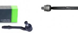
Repair request
Standard problems
The most common malfunction of the device on Toyota Corolla is the occurrence of knocking and crunching noises. In this case, there may not be any problems with the steering control. Extraneous sounds may go away after the tightening.
In most cases, the cause of knocking is backlash. Many car owners think that the place where play occurs is the EUR. To fix it, get a repair kit designed for this and rebuild the unit.
Simpler, but even more expensive: what breaks in steering racks with electric power steering, and how they are repaired
Features of work
Before we start talking about the types of electric amplifiers and their characteristic problems, let's say a few words about the algorithm of their operation.
Immediately after starting the engine, a self-diagnosis of the system is performed to confirm its functionality. In the neutral position, the electric motor does not work: the entire system is waiting for active action. As soon as you start turning the steering wheel, the signal from the steering angle and torque sensor goes to the ECU, which in turn gives a command to the electric motor, which makes your life easier. Moreover, the nature of the operation of the electric booster will be different depending on the speed of the car: in this way, progressive operation of the electric power steering is achieved. After going through a turn and gradually removing force from the steering wheel, the system will return the wheels to the neutral position.
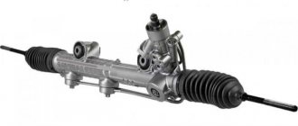
Articles / Practice Expensive and difficult: what breaks in steering racks with power steering, and how they are repaired A rack and pinion steering mechanism with an integrated power steering system, or, more simply, a power steering rack, is something that the owner of any vehicle hopes to avoid repairing… 38271 0 5 01/25/2017
Surely, owners of front-wheel drive cars with a transverse engine have noticed how the car pulls a little to the side during an active start. This is due to the different lengths of the drive shafts on the right and left sides. So, models with electric power steering can also steer the wheels a little, thereby compensating for the slip. In general, the force on the steering wheel is completely under the control of the EUR - and therefore it is on its conscience that the “emptiness of the steering wheel” and the “artificial force” that is so often talked about and about which numerous journalists complain.
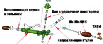
What are electric amplifiers?
These systems are divided primarily according to the location of the power unit (electric motor): on the steering column (almost under the steering wheel) or on the steering rack. In the first case, the steering mechanism will be the most common, for example, as in a V8 or Nissan Micra, and in the second, an electric motor or drive is integrated into the design. Today, in practice, we will look at a more interesting option with a rail-mounted amplifier.
On the steering mechanism itself, the electric motor can be installed in different ways - either separately, or as part of the body of this steering mechanism. There is also a distinction between the type of rack rod drive: an additional gear or a movable screw-nut connection.
1 / 3
2 / 3
3 / 3
In the latter case, the electric motor can transmit rotation through a belt drive, or the drive can be direct (as in Lexus GS racks).
To understand when and how much it is necessary to “help” the driver turn the steering wheel, the system uses data from several sensors - a torque sensor on the steering gear shaft, a steering wheel position sensor, a crankshaft speed sensor and wheel speed sensors. The only sensor that relates directly to the power steering system is the torque sensor.
More about the device
Now let's look at three different designs: rack-and-pinion steering, parallel-drive racks, and direct-drive racks. Each of them has its pros and cons – now we will outline which ones.
Racks with an additional gear incorporate an electric motor that rotates a gear through a worm gear, very similar to the one we rotate through the steering shaft. In this case, on the rack itself there are two notches of teeth. Everything about this design is not bad, but the friction losses are high: after all, it is a worm gear. With this design, the electric motor often has its own housing.
Parallel drive racks are the name given to a mechanism in which rotation from an electric motor is transmitted through a belt to a nut, or, more precisely, to a “screw-nut” pair.
The screw here is a rod with a thread on one side and a serration of teeth on the other.
Between the nut and the screw there are balls through which rotation is transmitted - they also act as a bearing. It works like this: when you start turning the steering wheel, an electric motor comes into action, rotating the nut in one direction or another, helping you turn the steering wheel.
Direct drive racks are a third option in which the steering rack housing is partly an electric motor housing, and the rack rod runs inside it. The rotation from the electric motor is transmitted through the already familiar “screw-nut” pair.
So, these are the main types of structures. Communication with the service technician allowed us to find out another important feature: there is a fundamental difference between Japanese and European slats. The Japanese “hide” the electric power steering control unit away from the steering mechanism itself - as a result, a long trail of wires stretches to the electric motor for control, communication and diagnostics. Europeans mount the control unit next to the electric motor or directly on it.
It’s hard to say which approach is correct. In the case of the “Japanese”, in order to remove the entire system, you need to pull out several meters of wiring and find the control unit itself - but in this case the unit is safe. With a European rail there will be no problems in terms of dismantling: disconnect two or three connectors, unscrew a couple of fastening bolts - and that’s it. However, the control unit in such a scheme is subject to various external influences.
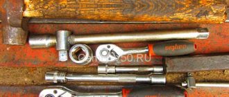
Primary diagnosis
The initial diagnosis of a car arriving at the service area is based on data received from the car owner: for example, a constant knocking noise or only when turning, a biting steering wheel, uneven force on the steering wheel or its absence. Based on this, the rail is dismantled and connected to a special stand (ours is MSG MS561) and errors are read. Using the stand, they simulate the operation of the engine in various modes and study the operation of the steering mechanism in more detail. This is done to localize the fault and understand whether the problem lies in the hardware or in the electrics.
1 / 5
2 / 5
3 / 5
4 / 5
5 / 5
In order about the problems
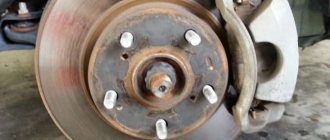
First, let's talk about the mechanical part of the system. Everything here is the same as with other slats: almost any problem is associated with the rupture of the slats’ boots and the ingress of water and dirt into it. Water means inevitable corrosion, and dirt means excessive wear of rubbing surfaces.
Wear of the side bushing is perhaps the most harmless thing that can happen to the rack rod. Washing out the lubricant from the screw-nut pair can lead to the pair biting or even jamming of the steering mechanism in one position.
In parallel drive mechanisms, moisture entering the belt leads to a sharp increase in its wear and, ultimately, rupture. A sharply increased force on the steering wheel is what the driver feels in this case.
It is rare, but it happens that due to moisture, the bearing of the electric motor is corroded - then you will hear the frantic howling of the latter during operation.
Wear in the gearing of the pinion shaft and rack rod is also a potential cause of boot rupture. But here you can try to cure the disease by tightening the rod stop.
When inquiring from the mechanic about the effect of water on the electric motor, if the drive is direct, we learned that there cannot be any special problems with the motor itself - good insulation of the wires does its job.
Having dealt with the mechanics, we move on to the “source of power” - the electrical part. There are not many potential problems here, but almost all of them are associated with significant costs.
For example, if the electronic system control unit is installed on a rail, it is often not protected in any way, so a pebble flying from somewhere can break the unit cover. And even if you notice this right away (which is unlikely), the unit will still have to be sent for replacement. At the same time, when we say “block,” we mean the entire rail, because blocks are not supplied separately, and at the moment only modest attempts are being made to repair this element. But all attempts are broken against the impregnable wall of the lack of software for programming ECU processors.
Failure of the torque sensor is another unpleasant situation on the road. In this case, the EUR “does not understand” with what frequency and force to help you turn the steering wheel and in which direction.
The amplifier will not turn off completely, since it will “take” the data from the speed sensor and steering wheel angle, but the EUR malfunction indicator will start to light on the dashboard. Moreover, it may happen that you need to turn the steering wheel to the right, but the electric motor will “turn” it to the left.
The sensors themselves can be analog or digital, which is why they have corresponding problems. Analog ones “suffer” from wear: this manifests itself in different forces on the steering wheel or the movement of the mechanism from the central position.
Digital ones, however, also suffer from wear and tear, but not of the sensor itself, but of the cable, which can simply fray.
We treat the rail
Mechanical problems with the rack rod cannot be treated in any way. Corrosion, excessive wear of threads or teeth will send you to purchase a new rod - no grinding or any other treatment is provided here. If everything is in order with the rod, and the cause of the knocking is wear of the side bushing or an increased gap in the gearing, then the bushing can be replaced without problems, and the gap can be adjusted by tightening the rod stop (the same as in the case of hydraulic boosters). Actually, there are simply no other solutions to hardware problems.
Articles / Practice Steering wheels and listen: how to diagnose problems with the steering rack, and what they entail The steering mechanism in the hierarchy of importance, undoubtedly, is on the same level as the brakes - that’s why attention to its technical condition should be appropriate, and “listen” to the car... 22702 2 6 11/16/2016
But with electrics, as mentioned above, everywhere you look there are problems everywhere. If the errors being read are related to improper operation, then you can try to remove them - but if these are breakdowns... Then the solutions are simple, but expensive. Judge for yourself: the slightest crack in the block cover means, in most cases, replacing the entire steering rack. Corrosion of an electric motor bearing means two ways to solve the problem: replacing the electric motor with the control unit or, again, replacing the entire rack assembly. By the way, replacing the assembly is the verdict of any official dealer: the manufacturer usually simply does not provide the possibility of repairing and restoring the steering mechanism with an electric steering gear.
And if the drive is direct, and water gets inside, then what will happen to the electric motor? Fortunately, nothing: it will be washed with gasoline, dried and sent back to service. Regarding this element of the EUR, the master generally noted that he had never encountered problems associated with the failure of the system’s motor.
A broken torque sensor can be treated by replacing the sensor. The only consolation for a design with an analog sensor may be the possibility of a slight adjustment (±1°) of the EUR. But if the sensor socket is significantly broken, then the adjustment will no longer help.
One of the most common reasons for sensor failure is damage to the boot that is installed above it. It begins to rot due to constant moisture and eventually collapses, sending the sensor for replacement - if such a possibility exists. If it is not there, then... You probably already guessed it: replacing the rack assembly. But the most annoying thing that can happen is a banal breakdown of the connector on the rail, because in this case, nothing other than replacing the rail assembly will help.
If you are lucky and the rack was repaired
Upon completion of the work, the rack is assembled and installed on the car.
After installation, it is necessary to initialize or adapt the EUR. This action is extremely important, since it allows you to “teach” the rack to see all the sensors and extreme positions. If this is not done, then the electric motor will spin “until victory”, as a result of which at the end of the stroke the rod will hit the stop with considerable force. After adaptation, the system will sharply reduce the force 5 degrees before the extreme position, protecting the rod from impact.
By the way, there is another small plus associated with adaptation and the very principle of operation of the electric amplifier. If you remember, in systems with hydraulic booster, you cannot hold the steering wheel in the extreme position for a long time - this can lead to overload and damage to the pump. But with a properly adapted electric power steering, everything will be fine in any position.
In conclusion
Despite the apparent simplicity of the electric power steering system and the virtual absence of the need to maintain it, it is worth remembering that it is still one of the most important systems in the car. After all, the EUR helps control the direction of movement - in other words, it makes movement subject to your will. Using the readings of the wheel, engine, and steering wheel sensors, the EUR requires double attention - therefore, if the slightest oddity appears in its operation, do not wait for a “revolt of the machines,” but go for diagnostics.
Special thanks for the preparation of the material and consultations to the company Master Service (MSG), contact details +7 (800) 350-99-23 (Moscow), +380 (57) 738-33-08 (Kharkov).
Survey
Have you encountered problems with the EUR?
Your voice
Total votes:
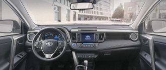
Steering column
Components
- Multifunction steering column switch assembly with slip ring
- Side cover No. 1 of the service hole of the steering column assembly
- Steering column assembly
- Telescopic part of the steering column assembled with the hinge fork
- Shift fork 6. Steering column intermediate shaft assembly
Steering column assembly
Removal and installation, disassembly and assembly
Removal
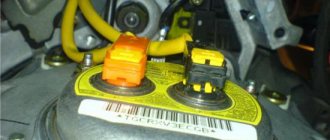
1. Study the warnings associated with working with elements of the passive safety system.
2. Set the front wheels to the straight-ahead position.
3. Disconnect the negative terminal from the battery and wait at least 90 seconds before starting any work.
4. Remove the steering wheel assembly (for more details, see the corresponding section in this chapter).
- Remove the steering wheel lower cover assembly (models without airbag).
- Insert a screwdriver into the groove on the bottom of the steering wheel cover and, using a lever movement, remove the cover from the grips.
- Press down on the spring to disengage the horn button pin assembly.
Note
Use a TORX screwdriver or similar tool to compress the spring.
- Press down on the two springs to disengage the horn button pin assembly.
Note
Use a TORX screwdriver or similar tool to compress the spring.
- Disconnect the horn wiring harness and remove the button from the steering wheel.
Attention
: Do not connect electrified measuring instruments to the airbag terminals. The squib may spontaneously fire and, as a result, receive serious injuries.
Attention
: To prevent the airbags from inflating spontaneously, do not use any memory devices. Failure to comply with this instruction may result in serious injury or death.
Attention
: Before starting any work, turn off the ignition and disconnect the negative terminal from the battery, then wait at least 3 minutes.
Attention
: Always work from the side of the airbag module, avoid working against the module.
- Remove the lower cover No. 3 of the steering wheel assembly.
- Using a screwdriver pre-wrapped with protective tape, pry and remove the steering wheel cover, placing the screwdriver in a small recess on the cover.
- Using a screwdriver pre-wrapped with protective tape, pry and remove the steering wheel cover, placing the screwdriver in a small recess on the cover.
Attention
: When removing the airbag module, guide it with the cover facing upwards.
- Check and make sure the ignition is turned off.
- Check and make sure that the negative terminal is disconnected from the battery.
- Using a T25H TORX wrench, press down on the retaining spring to disengage the pin, and then remove the front airbag module.
Note
— Be careful not to drop the airbag module. — Do not pull the wires or apply force to them when removing the airbag module.
Note
The key must be installed through the service holes of the steering wheel.
- Tilt the driver's front airbag module towards the driver's seat and hold it in this position with one hand.
- Disconnect the horn wiring harness connector.
- Using a screwdriver, unlock the wiring harness connector, and then disconnect the airbag module connector.
Note
When disconnecting the wiring harness connector, be extremely careful not to damage the wiring.
Attention
: After removal, the driver's airbag module must always be placed with the housing facing down and the decorative cover facing up. Never place the airbag module with the cover facing down. Failure to follow this instruction may result in serious injury.
Note
Repair of elements of the passive safety system is not provided. If it fails, the damaged element is replaced as an assembly.
Attention
: - Do not expose the airbag module to temperatures exceeding 90 degrees Celsius. — Prevent oil products, solvents and/or water from coming into contact with the airbag module.
Attention
: Always replace the airbag module mounting bolts after disassembling and reassembling.
Attention
: - Be extremely careful during installation to avoid damaging the airbag module wiring harness. — Before installing and tightening the mounting bolts, you must check and ensure that the holes in the module and the steering wheel are aligned, otherwise the airbag module may be damaged.
- Remove the ornament (facing panel) of the steering wheel assembly (models without remote control switches). Unscrew the two fastening screws. Disconnect the six guides and two claws to remove the trim panel from the steering wheel.
- Remove the remote control switch for the vehicle's electrical systems.
- Remove the main cruise control switch.
- Unscrew the steering wheel mounting nut.
- Place alignment marks (a) on the steering wheel and steering column main shaft.
- Using a special tool, remove the steering wheel from the steering column shaft assembly.
Note
Use special tools: 09950-50013 (09951-05010, 09952-05010, 09953-05020, 09954-05021).
Note
Apply a little lubricant to the threaded part and edge of the special tool (09953-05020) before using it.
- Remove the main lower steering wheel cover assembly.
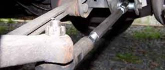
5. Remove the lower cover of the steering column assembly.
- Remove the three mounting bolts shown in the figure below.
- Disconnect the two clamps and six guides, and then remove the lower steering column cover assembly as shown in the figure below.
6. Remove the upper cover of the steering column assembly.
- Disconnect the two claws and release the two guides, then remove the upper steering column cover assembly as shown in the figure below.
7. Remove the steering column switch assembly with the slip ring.
- Disconnect three clamps. Remove the steering column switch assembly and slip ring from the steering column assembly as shown in the figure below.