A modern car is equipped with a large number of electronic sensors that monitor the correct operation of various systems. If a malfunction is detected, they send relevant information to the electronic engine control unit. It stores a specific error or fault code, which can be read during diagnostics. If the breakdown is serious, the Check Engine indicator lights up on the instrument panel. Thanks to this, the driver can correct the problem in a timely manner. In this article we will look at the most common error codes for Toyota cars. You will also learn how to perform diagnostics yourself.
Engine self-diagnosis
When operating Toyota cars in Russia in difficult climatic conditions, various engine problems often arise. These could be either serious breakdowns, which will be quite difficult to fix and it will be easier to install a contract engine, or failure of any sensors. If your “Check Engine” light comes on, don’t rush to get upset right away. First you need to carry out a simple self-diagnosis of the Toyota engine. This procedure will not take much time and will help you identify problems in the engine.
Resetting the computer Mazda Familia, Mazda 626, Mazda 323, Mazda Protege
- The engine is stopped. Remove the negative terminal from the battery.
- We get into the car and press the brake pedal. Hold for at least 20 seconds.
- We put the battery terminal in place.
- After resetting the computer, it is recommended to carry out training, especially if the car has an automatic transmission.
How to train a car with automatic transmission?
Before starting training, it is recommended to drive onto a straight road; it will take about 800 meters without interfering with traffic.
- Start the car, warm up the engine to operating temperature. Make sure that all additional equipment is turned off (lights, air conditioning, heater, etc.). If the engine is hot, you can immediately proceed to step 2.
- Secure the car with the parking brake, let it idle with the automatic transmission lever in position P or N for at least one minute.
- Move the automatic transmission selector to position D, do not start driving, let the car run for at least one minute. Use the brake pedal or parking brake to secure the vehicle in place.
- Release the brake and start driving. The movement should begin smoothly without abruptly pressing into the “floor” for a maximum of half the pedal stroke. It is necessary that all gears be switched, which corresponds to smooth acceleration to 60-70 km/h. Then slowly slow down the car until it comes to a complete stop.
- The training procedure for a car with an automatic transmission is completed; it will learn everything else on its own. It is worth noting that many automatic transmissions are adaptive and remember up to several dozen driving habits of the driver and turn them on themselves depending on how he presses on the gas.
How to train a car with a manual transmission?
To train a car with a manual transmission, no conditions are required. It is enough to let the warmed-up car idle for at least one minute. Before training, make sure that all additional equipment is turned off (headlights, air conditioning, heater, etc.).
Why perform engine self-diagnosis?
ATTENTION!
A completely simple way to reduce fuel consumption has been found! Don't believe me? An auto mechanic with 15 years of experience also didn’t believe it until he tried it. And now he saves 35,000 rubles a year on gasoline! Read more» When buying a used car you need to be very careful. Often, unscrupulous sellers hide from you problems in the engine, which will later have to be fixed, sometimes spending a lot of money on it. An excellent solution when inspecting such a car would be to diagnose the engine yourself, so as not to buy a “pig in a poke.”
Self-diagnosis must also be carried out for vehicle prevention. With some errors, the Check Engine light may not light up, although the fault will be present. This may result in increased gas mileage or other problems.
Rebooting the "brains" of the Audi 80
I would like to immediately note that this method is suitable for any “Mono-Jetronic” / “Mono-Motronic” control units manufactured by Bosch, regardless of the car it is installed on - VW, Audi, Renault or Fiat and others.
- Start and warm up the engine until the cooling fan turns on twice or until the oil temperature reaches +80 C.
- Stop the engine and turn off the ignition.
- Disconnect the connector from the Mono-Jetronic/Motronic control unit. Wait at least 10 minutes. This is necessary so that the contents of the control unit’s RAM are guaranteed to be erased (lost).
- Connect the connector back to the control unit.
Note. Theoretically, it is possible to replace steps 3 and 4 by disconnecting the negative terminal of the battery for the same time, and in most cases this simplification is acceptable. However, in some cases, due to the implementation features of the vehicle's electrical circuit, this solution does not work.
What needs to be done before diagnosis
Before performing an engine self-diagnosis, you must ensure that all indicators on the instrument panel are working correctly. The light bulbs may not light up or be powered by others, which creates the appearance of their operation. To save yourself from unnecessary steps and not have to disassemble anything, you can perform a visual inspection.
Fasten your seat belt, close the doors (to avoid unnecessary lights), insert the key into the lock and turn on the ignition (DO NOT start the engine). The “Check Engine”, “ABS”, “AirBag”, “battery charge”, “oil pressure”, “O/D Off” indicators will light up (If the button on the automatic transmission selector is depressed).
- The “ABS” lamp lights up when the ignition is turned on and should go out after 3 seconds;
- The “AirBag” lamp lights up when the ignition is turned on and goes out after self-diagnosis of the security system, after about 5 seconds.
Important: if you turn the ignition off and on without removing the key from the lock, the “AirBag” lamp will not light up again! Re-diagnosis of the system will occur only if the key is removed and reinserted.
- if the “O/D Off” lamp does not light up, press the button on the automatic transmission selector, the indicator should light up. And vice versa.
Next, start the engine:
- The “Check Engine” lamp should be constantly on when the ignition is turned on and go out immediately after starting the engine;
- The battery charge lamp behaves similarly;
- The oil pressure lamp lights up when the ignition is turned on and goes out 1-2 seconds after the engine starts.
If all of the indicated indicators behave as described above, then the instrument panel is in perfect order and you can perform engine self-diagnosis. Otherwise, you will need to fix any problems with the indicators first.
Battery disconnect method
Step 2: Discharge the remaining electricity. The next thing you should do is press and hold the car horn for about 30 seconds. This action will help drain the car battery.
Step 3: Wait and reconnect the battery. After disconnecting the battery cables and draining the remaining electricity, all you have to do is wait about 15 minutes and then plug the battery back in. Error codes will be cleared. (Note: This method may not work on some vehicles.) If after this procedure the “check” lights up again, this may mean that the problem is still much more serious.
How to read error codes
After closing the indicated contacts, get into the car and turn on the ignition (you DO NOT need to start the engine). Error codes can be read by counting the number of times the Check Engine light flashes.
If there are no errors in the memory, the indicator will blink at intervals of 0.25 seconds. If there are any problems with the engine, the light will blink differently.
- Every 0.5 seconds the indicator will first display tens, then, after a pause of 1.5 seconds, units after 0.5 seconds.
- If the memory contains more than one error, then the pause between them will be 2.5 seconds.
- After the system displays all errors, they will begin repeating after 4.5 seconds.
Legend:
Modern scanners
There are now many scanners available for reading car error codes that completely decipher error codes. These programs are translated into Russian, are easy to use and allow you to configure vehicle parameters. For example, the time when the headlights go out after turning off the ignition, after how many seconds the lights in the cabin go out when boarding, disembarking, and more.
The car owner should think about purchasing diagnostic equipment. Not bad manufacturers of diagnostic devices: Launch, ELM, Autel, Autocom, Carman.
Toyota self-diagnosis.
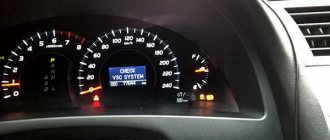
Modern Toyota cars, and other brands as well, are quite progressive mechanisms that have the ability to automatically control their own systems and sensors. If errors are found in operation, they signal the driver about the presence of a malfunction on the dashboard with a warning indicator lamp. Models with a digital display may even display an error code or the name of the faulty unit.
Toyota self-diagnosis begins with the fact that you first need to locate the corresponding diagnostic connector. This connector may be located under the hood, in the engine compartment and/or under the driver's instrument panel. In cars of this brand, three different types of self-diagnosis connectors were used:
Connector type DLC1 is located in the engine compartment, and connectors DLC2, DLC3 are located under the driver’s dashboard.
Errors during self-diagnosis are read by the blinking of the indicator lamp of the corresponding readable unit. For example, engine malfunctions must be read by the flashing of the “Check engine” lamp (engine image).
We dump our brains on Mitsubishi Karizma
According to the display, if there is no standard radio with a “Disp” button (it remains in a text file on the computer, I can’t check it now, but I think I tried it before, everything worked on the first Kara with a non-original radio).
Press and hold the left button, turn on the ignition (do not start the engine), while holding the left button pressed - the SET button - you can switch the computer readings
To see the consumption when the engine is on and the “power reserve” display is set, press M (with the left button pressed). The display proceeds to set the consumption readings: liters per kilometer or kilometers per liter, and at the same time displays the current consumption. Pressing Set returns everything to its place. Tested on cars with and without standard radio. The readings are reset with the same long press of the left button.
To switch modes, you need to simultaneously press the left and set. Doesn't have to be long. This all works when you turn on the ignition with set pressed. If you just turn on the ignition, the mode cannot be changed.
Hold the “A” button longer, the one closest to the steering wheel. And the reading that was selected will be reset to zero.
How to enter the display service mode
We press and hold the nameless button, turn on ACC, hold the button all the time, press H twice, then SET and enter the service, switching SET.
The reset is done this way: on the BC display, press and hold for 6 seconds (or until reset) the leftmost button.
We train our brains on Mitsubishi Karisma after resetting
- Warm up the engine to operating temperature, turn it off, remove the battery terminal for 10-20 seconds, and put it on.
- With consumers turned off, turn on the ignition for 10 s, turn off for 20 s, start the engine and let it idle for 10 minutes (all consumers should be turned off!).
- Turn off for 20 seconds, start again, turning on all possible loads (headlights, air conditioning, radio, heated seats, windows, interior lights, etc.), let it run for 10 minutes.
- Turn off the ignition for 10-20 s.
For everyone whose idle speed floats after they removed the terminals from the battery for some reason or reset their brains. After this, you need to train the computer XX again and this is described in detail in the instructions. For those who don’t have them, I’ll explain. Under the hood is a fuse and relay box. — Open the lid, find the air conditioning relay and its 25A fuse, after warming up the internal combustion engine to operating temperature, take out the whole thing. — Start the car and let it idle for 10 minutes, it may float a little but be patient. — After 10 minutes, turn off the car, put the relay and fuse in place, close the lid and hood, start it and enjoy smooth speed. PS This procedure perfectly regulates the idle speed, but only if the engine is OK.
How to do a Toyota self-diagnosis?
In order to start engine self-diagnosis, you need to close the “TE1” and “E1” contacts in the DLC1, DLC2 connectors in the diagnostic connector with a paper clip, and if self-diagnosis is carried out using the DLC3 connector, then close the “TC” and “CG” contacts.
The location of the contacts, by the way, is usually located under the protective cover of the connector. After this, turn on the ignition and observe the warning lamp. If there are no faults, the lamp blinks constantly at a frequency of a quarter of a second. If there are problems, the blinking of the lamp displays the fault code in digital form. First of all, the number of tens is displayed by long moments of lamp burning, after (after 1.5 seconds) units are displayed by more frequent blinking of the lamp. For example, three long and two short lamp beeps indicate code “32”. If there is more than one fault in the memory, then the next code is displayed after an interval of about 2.5 seconds. All codes are repeated in a cyclic circle, the pause between rows of codes in a circle is 4.5 seconds.
You can decipher the code using the table of fault codes for your car. This table is very often published in service books for repairing a specific car. In addition, the World Wide Web contains special sites with databases of fault codes for most modern cars and their decoding; application stores of modern smartphones, by the way, can also contain programs of this kind, which is very convenient.
In the same way, you can diagnose other systems:
To do this, you need to close or open the necessary connectors in the diagnostic block. Which connectors need to be closed to diagnose the corresponding mode in brief:
- The automatic transmission is read by the “O/D OFF” lamp (connector DLC1: “TE” – “E1”; connector DLC3: “TC” – “E1”);
- SRS by the corresponding “SRS” warning lamp, sometimes it is found in the form of a pictogram of a deployed airbag (connector DLC1: “TE” – “E1”; connector DLC3: “TC” – “E1”);
- 4WS system also by the corresponding indicator (DLC1 connector: “TC” - “E1”);
- ABS system (the connectors in DLC1 are closed: “TC” – “E1”, and the jumper from “WA” – “WB” is removed; after reading is completed, the jumper must be returned to its place).
In conclusion, I would like to note that the Toyota self-diagnosis system is the first direction of movement towards a malfunction. And we cannot immediately talk about a specific failure of any sensor, because a simple interruption in the power supply to the circuit or its contamination is possible. So, having decided on the direction, it is necessary to test a specific node for performance.
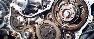
Sensors
One of the main links in a car's electrical system are sensors. They are the first to respond to detected problems. Malfunctions of the sensors lead to the fact that the sensor itself switches to an emergency mode of operation or to a complete stop of a particular component of the car.
Therefore, it is important to know where the sensors are located on Toyota Auris, how to determine their malfunction and replace them. The table shows some types of Toyota Auris sensors
The table shows some types of Toyota Auris sensors
| Sensor type | Where is |
| Crankshaft | Front of the engine |
| Camshaft | Front of the engine |
| Air flow | Near the air pipe |
| Reverse | checkpoint |
| Automatic transmission | Automatic transmission |
| Speeds | checkpoint |
| Collisions | Inner side of the bumper |
| Rain | Windshield |
| Brake pad wear | Brake pads |
Toyota diagnostics with a paper clip
Let’s say your check light comes on while you’re on the road, but you don’t have a diagnostic adapter at hand. To independently read an error without the help of additional equipment, you can use an ordinary paper clip. Such diagnostics can be carried out on almost every machine. We will talk about this method using Toyota cars as an example.
Preparatory stage
1) To read codes on older models with a diagnostic connector DLC1, which is located under the hood, you need to jumper outputs TE1-E1. The connector diagram is shown in the picture:
2) To read codes on cars with a DLC3 (OBD2) connector, which is usually located inside the car, you need to jumper the TC-CG outputs:
Reading codes
– Turn on the ignition – After 4 seconds, read the code by the number of flashes of the “Check” light – Remove the jumper from the outputs
Reset errors
– Turn on the ignition – Press the brake pedal eight or more times within an interval of three seconds. The indicator should display the normal code (blink 2 times per second). – Remove the jumper from the outputs
Engine error codes 12 - Crankshaft position sensor (P0335) 13 - Crankshaft position sensor (P0335, P1335) 14 - Ignition system, coil No. 1 (P1300) and No. 4 (P1315) 15 - Ignition system, coil No. 2 (P1305) ) and No. 3 (P1310) 16 — Automatic transmission control system 18 — VVT-i system — phases (P1346) 19 — Accelerator pedal position sensor (P1120) 19 — Accelerator pedal position sensor (P1121) 21 — Oxygen sensor (P0135) 22 — Coolant temperature sensor (P0115) 24 - Intake air temperature sensor (P0110) 25 - Oxygen sensor - lean signal (P0171) 27 - Oxygen sensor No. 2 31 - Absolute pressure sensor (P0105, P0106) 34 - Turbocharging system 35 - Turbo Pressure Sensor 36 - CPS Sensor (P1105) 39 - VVT-i System (P1656) 41 - Throttle Position Sensor (P0120, P0121) 42 - Vehicle Speed Sensor (P0500) 43 - Starter Signal 47 - Auxiliary Throttle Position Sensor 49 — Fuel pressure sensor (D-4) (P0190, P0191) 51 — Switch status 52 — Knock sensor (P0325) 53 — Knock signal 55 — Knock sensor No. 2 58 — SCV drive (D-4) (P1415, P1416, P1653 ) 59 - VVT-i signal (P1349) 71 - EGR system (P0401, P0403) 78 - Injection pump (D-4) 89 - ETCS drive (P1125, P1126, P1127, P1128, P1129, P1633) 92 - Cold start injector ( D-4) (P1210) 97 - Injectors (D-4) (P1215) 98 - Brake booster vacuum sensor (C1200)
ABS error codes 11 Open circuit in the solenoid valve relay 12 Short circuit in the solenoid valve relay circuit 13 Open circuit in the electric pump relay circuit 14 Short circuit in the electric pump relay circuit 21 Open or short circuit in the front right wheel solenoid valve 22 Open or short circuit in the front left wheel e/m valve 23 Open circuit or short circuit in the rear right (left) wheel e/m valve 24 Open or short circuit in the rear left (right) wheel e/m valve 31 Malfunction of the front right wheel speed sensor 32 Malfunction front left wheel speed sensor 33 Malfunction of rear right wheel speed sensor 34 Malfunction of rear left wheel speed sensor 41 Battery voltage too high or too low 43 Malfunction in deceleration sensor circuit 44 Open or short circuit in deceleration sensor circuit 49 Open circuit brake light switch 51 Short circuit or open circuit in the electric pump power supply 71 Low signal level from the front right wheel speed sensor 72 Low signal level from the front left wheel speed sensor 73 Low signal level from the rear right wheel speed sensor 74 Low signal level from the rear left wheel speed sensor 75 Incorrect signal change from the front right wheel speed sensor 76 Incorrect signal change from the front left wheel speed sensor 77 Incorrect signal change from the rear right wheel speed sensor 78 Incorrect signal change from the rear left wheel speed sensor 79 Deceleration sensor fault
Decoding combinations
Gasoline internal combustion engines
First, let's look at deciphering the combinations of self-diagnosis faults inherent to Toyota gasoline engines.
| Combination | Decoding |
| 12, 14 | The control unit informs the car owner about the incorrect operation of the crankshaft position control sensor. |
| 14,15 | A breakdown of one of the four ignition coils has been reported. |
| 16 | Incorrect operation of the transmission has been registered. It is recommended to carry out a more thorough check of the gearbox. |
| 19 | Incorrect accelerator pedal position. It could also be a problem with the pedal position sensor. |
| 21 | The oxygen sensor has failed. For correct operation, it is recommended to replace the device. |
| 22 | The refrigerant temperature control device in the refrigeration system sends an incorrect signal to the BC. The sensor needs to be replaced. |
| 24 | The intake air temperature control sensor is broken. |
| 25 | The oxygen sensor sends an incorrect signal to the on-board computer. In particular, the BC recorded a signal that the mixture in the injection system was too lean. |
| 31 | The control unit reports incorrect operation of the absolute pressure control device in the internal combustion engine system. |
| 34 | Malfunctions in the functioning of the turbocharging system have been reported. |
| 36 | The CPS sensor has failed. |
| 41 | The on-board computer reports an incorrect signal coming from the throttle position control device. |
| 42 | The driver is notified of a breakdown of the vehicle speed sensor. |
| 43 | The on-board computer receives an incorrect signal from the starter. A thorough check of the mechanism should be carried out. |
| 49 | Incorrect operation of the fuel pressure monitoring device. It is necessary to replace the sensor and check again. |
| 52, 53, 55 | Incorrect operation of one of the knock sensors. The device should be replaced. |
| 92 | Incorrect operation of the cold start injector. The element must be replaced. |
| 98 | A breakdown of the vacuum control device in the vacuum brake booster was registered. |
Diesel internal combustion engines
Next, let's look at deciphering the errors that occur when diagnosing Toyota cars with diesel engines.
| Combination | Decoding |
| 12 | A broken crankshaft sensor has been reported. |
| 13 | The control unit has detected a breakdown in the operation of the shaft speed control device. |
| 14 | A breakdown in the operation of the injection timing adjustment valve was detected. |
| 15 | Indicates that the throttle servo is not operating properly. |
| 17 | There are problems with the control unit. It is necessary to make a more accurate diagnosis of the block. |
| 18 | Problems have been detected in the operation of the electromagnetic bypass valve. The device should be replaced and diagnostics performed again. |
| 19 | The clutch pedal position control device does not work correctly. Replace the sensor. |
| 22 | The antifreeze temperature control mechanism in the cooling system has failed. |
| 24 | The intake air temperature sensor has failed. |
| 32 | The on-board computer registered a malfunction in the functioning of the correction resistors. |
| 35 | Malfunction of the boost pressure control device. Replace the sensor and re-diagnose the vehicle. |
| 39 | Incorrect operation of the fuel temperature sensor. |
| 42 | The vehicle speed sensor has stopped working. The device must be replaced. |
| 96 | There is a malfunction in the EGR valve position sensor. |
Automatic transmission
| Combination | Decoding |
| 11 | This combination means that no malfunctions have been identified in the operation of the automatic transmission system. |
| 37 | A malfunction of the unit input shaft speed control device has been reported. |
| 38 | Indicates a failure of the transmission fluid temperature sensor. To prevent damage to the unit, you should replace the sensor, and then do the diagnostics again. |
| 42, 44 | There has been a malfunction in the output shaft speed sensor. It is recommended to replace the device for correct operation of the unit. |
| 46 | The hydraulic accumulator pressure control solenoid has failed. |
| 61 | There is a malfunction in the speed sensor. The device should be replaced. |
| 62, 63 | The first or second solenoid has failed. |
| 64 | The control unit informs the car owner about the incorrect operation of the torque converter lock-up clutch solenoid. |
| 73 | The on-board computer detected incorrect operation of the center differential lock clutch solenoid. |
Other codes
Next, let's look at the error codes that appear when diagnosing a Toyota using special equipment. The list of errors is far from complete, but the most common malfunctions are considered.
| Combination | Decoding |
| c1201 | This combination indicates that the motor is not operating correctly. in practice, such an error occurs if the engine speed drops below 500. |
| p0171 | The combination indicates that the fuel mixture level in the engine is too lean. |
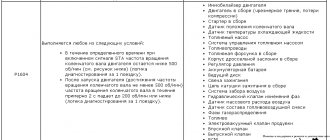
| p1604 | The car's on-board computer reports a breakdown of the intake system. A detailed check of the system should be carried out. |
| p1656 | An open or short circuit has been reported in the VVT system. Also, the on-board computer could record a breakdown in the operation of the VVT valve or electronic control unit. |
| b1801 | This code indicates an open circuit in the squib circuit on the driver's seat side. The wiring should be checked for shorts and breaks. |
| p1349 | Indicates incorrect operation of the VVT-i valve. The device must be replaced. |
| c1241 | The on-board computer reports that the pressure limit switch in the ABS unit is closed. The circuit should be checked for breaks and short circuits. |
| p0352 | Malfunctions were detected in the operation of the ignition system circuit. To ensure proper operation of the transport, check the circuit more accurately. |
| p0051 | The oxygen sensor heating device has failed. |
| b0101 | The control unit reports incorrect operation of the security system, in particular the airbags. |
Toyota self-diagnosis.
Modern Toyota cars, and other brands as well, are quite progressive mechanisms that have the ability to automatically control their own systems and sensors. If errors are found in operation, they signal the driver about the presence of a malfunction on the dashboard with a warning indicator lamp. Models with a digital display may even display an error code or the name of the faulty unit.
Toyota self-diagnosis begins with the fact that you first need to locate the corresponding diagnostic connector. This connector may be located under the hood, in the engine compartment and/or under the driver's instrument panel. In cars of this brand, three different types of self-diagnosis connectors were used:
Connector type DLC1 is located in the engine compartment, and connectors DLC2, DLC3 are located under the driver’s dashboard.
Errors during self-diagnosis are read by the blinking of the indicator lamp of the corresponding readable unit. For example, engine malfunctions must be read by the flashing of the “Check engine” lamp (engine image).
Resetting the brains of VAZ
In order to “reset the brain” or reboot the computer of the VAZ car, press the daily mileage reset button, without releasing it, turn the key to start. The instrument combination goes into self-test mode. There is a threefold deviation of all needles (tachometer, speedometer, engine temp., fuel). If at this time you press the engine daily mileage button again on the mileage panel, the firmware version will appear, if you press it again it will show errors. If there are no errors, it shows ZERO. If there are errors, remember them, press the daily mileage key for 2-3 seconds and reset the error (ZERO appears).
Resetting the computer after removing the battery on a VAZ
When the battery is removed, the computer is reset and current data on the operation of the sensors is erased. This is where the main problem lies. Since when installing the battery back, the basic conditions for the normal further functioning of the car are not met. To do this, it is necessary to correctly connect the new battery so that the engine will subsequently delight you with its operation and not cause trouble.
The second and third generations of Avensis, produced in 2003-2009 and 2009-2018, can boast of having a well-developed self-diagnosis system. Toyota Avensis fault codes are among the most detailed among all cars in this class.
Error checking occurs using blinkers, which are displayed by flashing the check indicator or through connecting diagnostic equipment to the DLC2 connector. The latter can be found under the steering wheel, inside the car.