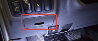
The 7th generation Toyota Hilux was produced in 2004, 2005, 2006, 2007, 2008, 2009, 2010, 2011, 2012, 2013, 2014 and 2015 with the designation AN10 / AN20 / AN30. During this time, the model underwent restyling. In this article you will find a description of the locations of electronic control units, the purpose of fuses and relays of the 7th generation Toyota Hilux with photographs and block diagrams. Let's highlight the fuse responsible for the cigarette lighter.
Depending on the region of delivery and year of manufacture, a different design of blocks and arrangement of elements is possible. Check the information with your diagrams on the block cover.
Features of the location of blocks in a car
Hilux cars were supplied both to the domestic market and to countries with left-hand traffic. The location of the junction boxes depends on the location of the steering control.
The type of engine affects the list of protective elements (for example, a diesel engine does not need an ignition system, but is equipped with glow plugs for winter starting). The installation location or the rating of the inserts depends on the generation of the pickup truck and the type of transmission (manual or automatic).
Steering wheel on the left
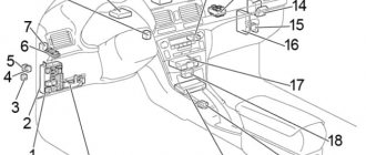
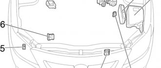
On vehicles model 2015, 2021 or 2021 (up to 2021) intended for the European, Russian or North American markets, the elements are located in:
- left side of the engine compartment (next to the battery);
- lower part of the dashboard (under the steering column cover);
- facing the A-pillar near the driver's left foot.
Location of blocks in a car with the steering wheel on the left.
Steering wheel on the right
The power fuse box on pickup trucks for the Japanese domestic market is located in the engine compartment. The additional box is located inside the instrument panel. To access it you will need to remove the covers under the glove box. 2 more modules are located behind the glove compartment. To access them, you need to remove the container for storing small items. The location of the boxes is unchanged for cars produced in 2012, 2013 or 2014. On Japanese models, the fuses are located under the lower A-pillar trim on the passenger side.
Location of blocks in a car with the steering wheel on the right.
www.crown-club.ru
integrated relay (or rear lights do not light up)
integrated relay (or rear lights do not light up)
colt46 » 02 Sep 2013
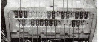
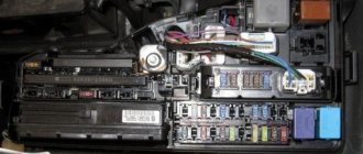
This was discussed somewhere, but the top didn’t find anything, and the photos there were deleted. Therefore, I want to share my experience with you. In general, my rear lights did not light up, and they still don’t light up, but more on that later. The TAIL fuse in the cabin and the rear light switch rang, both are intact and when the lights are turned on, the plus rings in it. I read all about the rear lights here and came across a top page that talked about an integrated relay. I decided to find it and check it out. And then I found it - it is located behind the fuse panel in the cabin, they connect to it from behind. Here it is: the integrated relay: before you pull it out, you need to disconnect this connector; when assembling it back, you must first connect it, because then plugging it back in will be very difficult and inconvenient. photo of the fuse box with the relay int removed, but the integrated relay itself and its insides are the culprit for the non-lit lights; here in the photo in the center you can see the culprits for the non-lit lights - melted fusible links (4 pieces)
I removed the switch 2 times, because the first time I foolishly soldered insulated wires there, when checking the lights were on, but smoke and the acrid smell of burning wires appeared in the cabin, I ran out of the cabin in a panic and unfastened the terminal from the ground, fortunately it was not twisted. The second time, instead of these, I soldered a single-core BARE wire. And after I put everything back together, my joy knew no bounds, all the lights were on as they should be, even the standard license plate lights came on, which I didn’t even imagine were working. But the happiness did not last long. After a ten-minute drive, the rear lights disappeared again, as did the license plate illumination.
It turned out that I had a short circuit somewhere. When the battery was removed, the terminals rang, there is contact from minus to plus and the resistance is minimal. I disconnected all the fuses one by one, both under the hood and in the cabin, there is still a short circuit. Who can advise where to dig? The display shows a malfunction of the headlights and backlight. It seems like I looked at all the lighting and everything seems to be ok. The front lights all work properly. The rear feet also work, except for the overall ones, of course. I also checked the wiring from the rear lights to the fuses in the cabin.
Location and diagram of fuses in the cabin
The design and rating of the inserts in the interior units (on pickup trucks after 2004) do not depend on the location of the steering. When looking for a location to install a junction box or circuit board, consider the vehicle's market.
The elements are located not only inside the instrument panel, but are also partially located under the lining of the central tunnel.
LHD
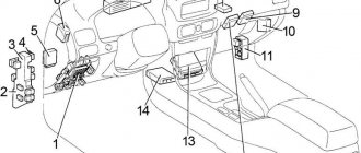
On left-hand drive vehicles, the following installation diagram is used:
- Near the instrument cluster there is an air conditioning controller and a main fuse box. The immobilizer amplifier is located next to the ignition switch. To the right of the column are the all-wheel drive system controller and relays for controlling side lights, head lighting, turn indicators and air conditioning.
- Under the center console are located the airbag control unit (rigidly fixed in the floor tunnel) and the automatic transmission selector controller (not available on models with manual transmission).
- On the front passenger side there are control units for the engine, supercharging system and gearbox. A relay box is mounted on the side of the glove box.
LHD scheme.
RHD
Cars with right-hand drive are distinguished by mirror images of elements inside the instrument panel. The center console contains hidden control units for airbags and the automatic transmission selector. The diagrams show the location of parts on Hilux pickups for foreign markets and domestic use in Japan.
RHD diagram.
What to do if your 2012 Hilux transfer case sensor light is flashing
Location
The transfer case is located behind the transmission, directly in front of the center of the vehicle.
Transfer case function
Once power is transferred from the engine to the transmission, it is sent through the transfer case to the rear wheels, or to the front and rear wheels simultaneously if the driver activates all-wheel drive.
For reference! In situations where a rear-wheel drive car gets stuck due to not having enough weight on the drive wheels, the transfer case allows the car to pull itself up with the help of the front axle.
When switching the transfer case between two- and four-wheel drive modes, follow the manufacturer's recommendations. Shifting the transfer case at too high a speed will damage the transmission and cause the vehicle to fail.
Error indicators
The transfer case is a mechanical device that requires regular maintenance to function properly.
The condition of your tires is a vital factor. Slight differences in wheel diameter and one or more flat or excessively worn tires can cause difficulty shifting. Therefore, it is necessary to inflate all tires to the recommended pressure, especially when the vehicle is running at maximum load. Front-wheel drive should be avoided on hard road surfaces as this will cause rapid wear of the front tires.
Engine error
Transfer case switch error
Transfer case control module error
The module is the main microprocessor that controls the electronic all-wheel drive system. It is responsible for interpreting commands from the controller through the transmission mode switch and controlling the vehicle components to provide the required range or mode of operation of the device. If this module has problems with programming or internal circuits, it will activate the four-wheel drive system sensors.
Front axle drive
Wiring
The all wheel drive system light also comes on due to a wiring problem. If a wire is corroded or broken, the open control circuit will not receive the signals needed for proper operation. A broken wire can damage the module, causing a signal to be received that confirms proper operation. In this case, the module signals this malfunction using the all-wheel drive system indicator.
Manual gearbox failure
Correct functioning of the gearbox is necessary so that the vehicle's transmission system does not deteriorate and does not affect the operation of the engine.
There are three symptoms that indicate a possible breakdown of the manual transmission:
- Lock when trying to change gears: To prevent two gears from being engaged at once, safety bolts block access. If they are worn, the output shaft will seize as the two activated gears cause it to rotate at two different speeds. In this case, you need to install new safety bolts on the box.
- Noise when trying to engage gear: If noise is detected when shifting gears, it is most likely a faulty clutch, so it is recommended to tighten the clutch cable and adjust the stop again so that the clutch is completely disengaged, and also bleed the hydraulic control circuit. It is also necessary to take into account the wear of the synchronizer assembly and replace worn o-rings.
- Difficulty engaging gears: The clutch control may have become loose and the cable needs to be tightened again. If the situation persists, lubricate the switch drive rod. If the rod is not positioned correctly, adjust it.
If the transmission continues to cause problems, there is likely an internal problem. In case of internal malfunctions, the gearbox is dismantled and the condition of bearings, gears and other components is checked. Then the faulty parts are replaced.
Automatic transmission failure
We can talk about automatic transmission failure if:
- Gears slip when trying to change gears. This is most likely due to poor lubrication, so it is recommended to bring the oil level to the marked limit.
- Insufficient acceleration in all gears. At low speeds, acceleration drops if the torque converter breaks and interferes with the unidirectional reactor bearing. It is advisable to replace the torque converter, but check the oil level first, as insufficient lubrication causes the same problem.
- There is no gear shifting. This is a general failure that requires a full check, or the regulator is poorly adjusted, and then you need to check the pressure and adjust it again.
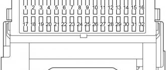
Safety block in the cabin
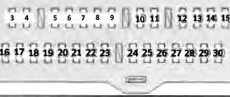
Inside the box near the driver's seat on the Hilux there are elements for protection (from 7.5 to 20 A):
- fuel injection systems;
- diagnostic module;
- brake lights and gear shift locking systems on automatic transmissions;
- interior lighting, side lamps (including daytime running lights) and fog lights;
- sockets for additional equipment;
- instruments and engine starting systems;
- air conditioning system;
- neutralizer and filter for soot particles;
- cigarette lighter;
- acoustic system and electric mirror drive;
- airbag controller and fuel pump;
- windshield cleaning and washing systems;
- general electrical circuits of external lighting, fuel supply, steering sensors, display in the instrument cluster, seat belt buckle indicator, seat heating systems, mirrors and windows.
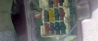
Fuse box in the cabin.
To access the block in the instrument panel you must:
- Press the lid latch.
- Pull the clip down and remove the plug from the mounting socket.
- Find the faulty element and replace it using pliers.
To access the additional unit, you need to remove the threshold trim in the doorway, and then unscrew the nut securing the trim near the support for resting the driver’s foot. Plastic pliers for servicing the inserts are located on the removable module cover in the engine compartment. Reserve inserts are stored in free slots both inside the car and in a box next to the battery.
To replace the elements behind the glove box, you need to fold back the glove box and squeeze the walls, removing the box from the guide grooves.
Instrument lighting does not work on Toyota Hilux Surf
The car is from 1997, with a 1KZ engine. The backlight stopped working after I removed the dead alarm from it. I think the backlight wire was damaged in the process. That's just what it is. Maybe someone has a wiring diagram?
2 Reply from igor4737 05/30/2012 21:09:02
You didn’t remove 300 wires, go through it again.
3 Reply from 220 volts 05/30/2012 21:13:44
or maybe a comfort block
4 Reply from Maxim Shmyga 05/30/2012 21:32:41
igor4737, the fact is that the signaling system was not connected to the dashboard lighting in any way, i.e. I specifically did not touch this wire in the harness. maybe the contact in the block is simply broken, but you need to know which block to move. randomly is unsporting, but as a last option, there remains, of course, Volt822, what kind of comfort unit is this?
5 Reply from 777 white 05/30/2012 21:41:04
Some cars have a so-called “comfort block” - a box that powers the control of interior lighting (smooth fading), instrument panels, sometimes the climate system, DRLs and other functions. If it is on your car, then when installing the old alarm system they probably took some contacts from it.
6 Reply from 220 volts 05/30/2012 21:44:13
Me too, when I came to the electrician to look at the dimensions, he looked and said that it was a comfort block. He said business for 2 days and charged 1 t.r. for replacing light bulbs in three units. I said I’ll think about it and left. Now I’m wondering what kind of comfort block it is. It’s probably all electricians refer to this block when they themselves don’t know what’s going on. Be careful not to fall for this bait
7 Reply from 220 volts 05/30/2012 21:48:16
777 white, I used to have this in my cabin, the light dimmed when there were incandescent lamps before the diodes. And now, after a short circuit in the license plate illumination, there are no dimensions
8 Reply from 220 volts 05/30/2012 21:53:05
777 white, are you by any chance the auto electrician who charges for replacing three light bulbs in 10 minutes?
9 Reply from Maxim Shmyga 05/30/2012 22:03:11
777 white, but it’s not my car yet)) mine is on the avatar. When I checked the car yesterday, I turned on the lights - they worked; when I turned on the lights, the brightness of the backlight of the clock and something else decreased. It turns out that the “comfort block” is alive?
10 Reply from Maxim Shmyga 05/30/2012 22:09:04
11 Reply from 777 white 05/30/2012 22:13:32
777 white, are you by any chance the auto electrician who charges for replacing three light bulbs in 10 minutes?
No. And if I were you, I would first study the manual, then you would know where the comfort unit is located on your Tiger and what it affects
Heck, I just answered your question above.
12 Reply from Maxim Shmyga 05/30/2012 22:17:33
777 white, clear I was just talking to the owner of the mobile. it turns out that the tidy is on, but not all of it, before the alarm was removed there was no backlight on one half, and now on the other)) in short, electrics is the science of contacts
13 Reply from 220 volts 05/30/2012 22:26:24
777 white, not my thing to drip in threads. I like it thicker. Sorry for the flood
14 Reply from aziat 05/30/2012 22:54:21
777 white, clear I was just talking to the owner of the mobile. it turns out that the tidy is on, but not all of it, before the alarm was removed there was no backlight on one half, and now on the other)) in short, electrics is the science of contacts
Remove the tidy and clean the contacts on the light bulbs. There's nothing else to break there.
Some cars have a so-called “comfort block” -
On Surf, this block is nothing more than an ordinary variable resistor; its knob is located in right-handed cars on the panel to the right of the steering wheel.
Relay box in the cabin
The module is located behind the glove box. The mounting location of the box on Hilux pickups has not changed since 2004. The list of elements depends on the year of manufacture, but the location of the steering and engine type do not affect the unit.
Since 2011
After the modernization carried out in 2011, fuses for circuits began to be installed in the cabin:
- Systems for removing ice from rear-view mirrors (15 A). Since the fall of 2011, they began to use a 25 A insert to protect power windows and door locks.
- Electric windows (25 A). Since November 2011, the rating has been changed to 20 A. The insert protects the threads on the rear window and the gasoline injection system into the cylinders.
- Threads for removing frost from the rear window and gasoline injection nozzles (20 A). Since November 2011, the rating was reduced to 15 A and the wiring for heating the front seats was installed on the insert.
- Front seat heating systems (15 A). Later they began to use a 20 A fuse, an ABS service unit and a differential lock system.
- Rear axle differential locks and ABS module (20 A). Since the fall of 2011, a system for removing ice from the surface of rear-view mirrors has been connected to the 15 A insert).
Relay block in the cabin.
Inside the box there are relays:
- heated rear view mirrors and rear window;
- ignition systems.
Until 2011
The following fuses are installed inside the box:
- electric windows and door locks (25 A);
- electric heating of the rear window and fuel injection system (20 A);
- heated front seats (15 A);
- rear axle differential lock drive and ABS system (20 A);
- power windows (30 A);
- relay for controlling the ignition and the system of electric heating of the rear window surface.
Dimensions of Toyota Hilux do not light up
I measured it with a chain. There's supposed to be a thin sting there. It will pierce through the oxide
Added after 21 minutes 28 seconds:
I'll go tomorrow and pierce the wiring behind the cartridge. If the problem is not in the cartridge, then I will look for the ends on the side of the fuse box
Thank you. Really useful thought
so it shouldn’t be there on both.. one is probably a mass.
or on the size of the rear license plate illumination, if the illumination of course works.
Judging by this diagram, the marker and license plate illumination operate from one wire. If the backlight works, then the problem is in the headlight/its contacts or in a small section of the wiring.
If you want, write in a personal message - I have a relatively warm garage, we can dig around in the evening. The only thing is that the bottom (sills and fender liners) of the car will have to be “recovered at the car wash”.
black013 wrote: ChipBp ,
Judging by this diagram, the marker and license plate illumination operate from one wire. If the backlight works, then the problem is in the headlight/its contacts or in a small section of the wiring.
Thank you. In the morning I'll look at the license plate illumination and report back. Did not pay attention. I looked around all the time during daylight hours. Even warmer. I'll find you soon
Nope. Each consumer has its own wire from the fuse box - so that everything doesn’t fail at once and they don’t drive into the building :) At least that’s the case on Savets cars.
USA, according to the diagram - from one, you just need to find where the wire “splits”. and they seem to have a common fuse. fuse box on the driver
and pulling the wire from the backlight (as a temporary solution) is easier than from the size of the work light.
But first, I would carefully check the cartridge itself in the flashlight again, then check the power again (cleaned the terminals). Afterwards, I would find the other end of this wire, unhook it (if possible) and ring.
here is another diagram, more precisely, a description of another fuse diagram, judging by it, the power supply circuits of the dimensions are protected by cross-to-cross fuses, that is, the front left clearance and the rear right sit on one fuse, and even on Soviet cars - the license plate light “sits” on a wire or one of the lantern dimensions, or from each lantern.
ChipBp, in general, did you check the new (and old) lamps directly from the battery? Are both threads on fire?
Engine compartment
On Hilux vehicles built after 2004 with left-hand drive, the ABS brake system unit is located behind the battery and fuse box. A separate headlight control module is located under the bumper trim on the right.
In the upper left part of the engine compartment there is a control unit for glow plugs (diesel only) and controllers for gasoline injection systems.
On pickups for the Japanese domestic market, the engine relays are located on the right, and the ABS unit is located on the left fender liner (the headlight control system is located similar to LHD cars).
LHD
The fuses are installed in the box (from left to right and top to bottom):
- 3 spare elements;
- fog lights (7.5 A until 2013 and 15 A on later versions);
- sound signal (10 A);
- fuel injection control systems (25 A);
- low beam of the front right headlight (20 or 15 A);
- low beam of the front left headlight (20 or 15 A);
- high beam of the front right headlight (20 or 15 A);
- high beam of the front left headlight (20 or 15 A);
- microprocessor injection control unit (2 elements of 10 A each);
- door lock drive systems and power steering components (7.5 or 10 A);
- radios with built-in amplifier (15 or 20 A);
- lighting systems for devices, interior and instrument cluster (7.5 A);
- oxygen sensors in the catalytic converter and exhaust gas emissions reduction system (20 A);
- fuel injection control unit and throttle valve module (10 A);
- generator controller (7.5 A);
- hazard warning lights and direction indicators (15 A);
- air conditioning clutch (7.5 A)
- additional protection for door lock drives, radio and interior lighting (30 A);
- additional liquid heater (50 A);
- headlight cleaning systems (30 A, since 2011, the insert protects the electric seat drive circuits);
- ABS systems (40 A, since 2011, the insert protects the headlight washer circuits);
- air conditioning system (40 or 50 A);
- ABS systems (30 A);
- additional circuits of the ABS system (40 A);
- charging circuits (100 A);
- engine heating module before winter start-up (80 A);
- sound signal and injection system (50 A);
- starter and ignition circuits (30 A);
- main headlight harness (40 A);
- fuel pump and injection system (50 A).
Engine compartment LHD.
In the upper left part of the box there are relays for the starter, fuel supply system and glow plug or pump control. To the right are modules that support the instrument panel backlight control and head lighting.
RHD
Japanese vehicles use an identical junction box. All changes affecting pickups for Russia, the Middle East or North America also affected the internal model. The manufacturer did not provide original options only for Japanese customers.
Engine compartment RHD.
Fuse box in the engine compartment
The module contains spare fuses with ratings of 10, 15 and 25 A (installed from the factory and can be replaced by the owner with elements with different characteristics). The box contains relays for controlling headlights, an electric engine starter and additional high-power equipment.
For example, if the fuel injectors fail or there is no power to the glow plugs (for gasoline and diesel units, respectively), you need to check the condition of the relay.