Toyota Corolla E150
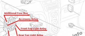
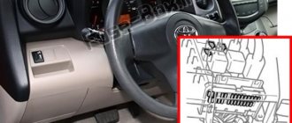
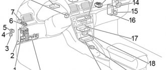
released in 2007, 2008, 2009, 2010, 2011, 2012 and 2013 and shipped worldwide. During this time, the model underwent restyling. In some regions it is known as Corolla Axio (Toyota Axio) and Corolla Altis. In this material we will show the location of electronic control units, describe in detail the fuses and relays of the Toyota Corolla in the 150 body with the locations of the blocks, their diagrams and photo examples of execution. Let's highlight the cigarette lighter fuse.
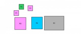
The number of elements in blocks and their purpose may differ from those presented. Check the description with your diagrams on the protective cover of the unit.
Blocks under the hood
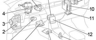
Layout diagram
General layout of blocks under the hood
Description
- The engine control unit
- Main fuse and relay box
- Glow plug relay
- Cooling fan control unit
- LHD: Headlight wiper relay
- Injector control unit (EDU)
- Relay block
- Gasoline: Brake control unit
- Diesel: Brake control unit
Main fuse and relay box
Installed on the left side under the smoke chamber.
Option 1
Scheme
Purpose
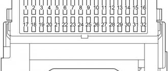
| F1 | 30A H-LP CLN - Headlight washer |
| F2 | 45A RDI FAN - Cooling system fan |
| F3 | 30A ABS NO.3 - ABS and VSC |
| F4 | 50A ABS NO.1 - ABS and VSC |
| F5 | 50A HTR – Air conditioning |
| F6 | 10A ECU-B2 - Robotic gearbox, air conditioning, Smart Entry system |
| F7 | 10A ECU-B - Instrumentation, electrical control unit, VSC, central locking, window lift drive |
| F8 | 15A RAD NO.1 - Audio system |
| F9 | 10A DOME - Interior lighting, trunk lighting, Smart Entry system |
| F10 | 20A STRG LOCK - Steering lock system |
| F11 | 30A AM2 - Engine starting system, Smart Entry system, injection system |
| F12 | 10A ETCS - Throttle Control System |
| F13 | 10A TURN-HAZ - Direction indicators and hazard warning lights |
| F14 | 7.5A ALT-S - Battery charging system |
| F15 | 7.5A AM2 NO.2 - Electrical equipment control unit |
| F16 | 50A H-LP MAIN - Headlights |
| F17 | 50A P/I - Fuel injection system |
| F18 | 80A GLOW — Engine preheating system (for diesel engines) |
| F19 | 60A EPS - Electric power steering |
| F20 | 120A ALT - Battery charging system |
| F21 | 15A IG2 - Fuel injection system, Smart Entry system |
| F22 | 10A HORN - Horn |
| F23 | 20A EFI MAIN - Fuel injection system |
| F24 | Reserve |
| F25 | Reserve |
| F26 | Reserve |
| F27 | 50A AMT - Robotic gearbox |
| F28 | 30A HTR SUB NO.3 – Air conditioning |
| F29 | 30A HTR SUB NO.2 – Air conditioning |
| F30 | 30A HTR SUB NO.1 – Air conditioning |
| F31 | 10A H-LP LH LO - Right headlight (low beam) |
| F32 | 10A H-LP RH LO - Left headlight (low beam) |
| F33 | 10A H-LP LH HI - Right headlight (high beam) |
| F34 | 10A H-LP RH HI - Left headlight (high beam) |
| F35 | 10A EFI NO.1 - Injection system |
| F36 | 10A EFI NO.2 - Injection system |
| F37 | 7.5A IG2 NO.2 - Starting system, Smart Entry system |
| 38 | FR DEICER - Cooling fan relay |
| 39 | IGT/INJ - Headlight switch relay |
| 40 | AMT - Automatic Transmission Relay |
| 41 | H-LP - Headlight relay |
Fuse and relay diagram Toyota Corolla 150 (2006-2013)
Detailed explanation with photos, electrical diagram of fuse and relay blocks for Toyota cars.
Engine compartment
LHD
RHD
- The engine control unit
- Fuse box
- Glow plug relay
- Cooling fan control unit
- LHD:
Headlight wiper relay - Injector control unit (EDU)
- Relay block
- Gasoline:
Brake control unit - Diesel:
Brake control unit
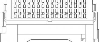
Fuse box in the engine compartment
| № | Name | A | Purpose |
| 1 | DOME | 10 | Interior Lighting, Trunk Lighting, Individual Mirror Lighting, Intelligent Entry & Start System, Wireless Control System |
| 2 | RAD NO.1 | 15 | Audio system, navigation |
| 3 | ECU-B | 10 | Body electrical control unit, power windows, instrument cluster, central locking, VSC, start-stop system, charging system |
| 4 | DCC | — | — |
| 5 | ECU-B2 | 10 | Transmission control unit, air conditioning, intelligent entry and start system, charging system, power windows |
| 6 | — | — | — |
| 7 | ECU-B3 | 7.5 | Multiport fuel injection system/sequential multiport fuel injection system |
| 8 | — | — | — |
| 9 | IGT/INJ | 15 | Gasoline: Multiport fuel injection system/sequential multiport fuel injection system, starting system |
| 10 | STRG LOCK | 20 | Steering wheel lock |
| 11 | A/F | 20 | Emission control system |
| 12 | AM2 | 30 | Starting system, intelligent entry and start system, fuse: "IG2 NO. 2" |
| 13 | ETCS | 10 | Throttle valve |
| 14 | TURN-HAZ | 10 | Direction indicators |
| 15 | ALT-S | 7.5 | Charging system |
| 16 | AM2 NO.2 | 7.5 | Body electrical control unit, start-stop system |
| 17 | HTR | 50 | Air conditioner |
| 18 | ABS NO.1 | 50 | ABS, VSC |
| 19 | CDS FAN | 30 | 1AD-FTV, 2AD-FHV: Cooling fan |
| ABS NO.3 | 30 | Gasoline (TMC*): ABS, VSC (*Toyota Motor Corporation) | |
| 20 | RDI FAN | 40 | Cooling fan |
| 21 | H-LP CLN | 30 | Headlight cleaners |
| 22 | — | — | — |
| 23 | — | — | — |
| 24 | — | — | — |
| 25 | — | — | — |
| 26 | H-LP MAIN | 50 | Fuses: “H-LP LH LO”, “H-LP RH LO”, “H-LP LH HI”, “H-LP RH HI” |
| 27 | P/I | 50 | Fuses: "EFI MAIN", "EDU", "HORN", "IG2" |
| 28 | — | — | — |
| 29 | P-SYSTEM | 30 | Multiport fuel injection system/sequential multiport fuel injection system |
| 30 | GLOW | 80 | Preheating system |
| 31 | EPS | 60 | Electric power steering |
| 32 | ALT | 120 | Gasoline: Charging system, fuses: “RDI FAN”, “H-LP CLN”, “ABS NO. 1", "ABS NO. 3", "HTR", "HTR SUB NO. 1", "HTR SUB NO. 2", "HTR SUB NO. 3", "ACC", "CIG", "ECU-IG NO. 2", "HTR-IG", "WIPER", "RR WIPER", "WASHER", "ECU-IG NO. 1", "SEAT HTR", "AM1", "DOOR", "STOP", "FR DOOR", "POWER", "RR DOOR", "RL DOOR", "OBD", "ACC-B", " RR FOG", "FR FOG", "SUNROOF", "DEF", "MIR HTR", "TAIL", "PANEL" |
| ALT | 140 | Diesel: Charging system, fuses: “RDI FAN”, “CDS FAN”, “H-LP CLN”, “ABS NO. 1", "ABS NO. 2", "HTR", "HTR SUB NO. 1", "HTR SUB NO. 2", "HTR SUB NO. 3", "STV HTR", "ACC", "CIG", "ECU-IG NO. 2", "HTR-IG", "WIPER", "RR WIPER", "WASHER", "ECU-IG NO. 1", "SEAT HTR", "AM1", "DOOR", "STOP", "FR DOOR", "POWER", "RR DOOR", "RL DOOR", "OBD", "ACC-B", " RR FOG", "FR FOG", "SUNROOF", "DEF", "MIR HTR", "TAIL", "PANEL" | |
| 33 | IG2 | 15 | Multiport fuel injection system/sequential multiport fuel injection system, starting system, intelligent entry and start system, fuses: "IGN", "METER" |
| 34 | HORN | 15 | Sound signal |
| 35 | EFI MAIN | 20 | Gasoline: Multiport fuel injection system/sequential multiport fuel injection system, start-stop system, fuses: “EFI NO. 1", "EFI NO. 2" |
| 30 | Diesel: Multiport fuel injection system/sequential multiport fuel injection system, start-stop system, fuses: “EFI NO. 1", "EFI NO. 2" | ||
| 36 | EFI MAIN | 30 | Multiport fuel injection system/sequential multiport fuel injection system |
| EDU | 20 | Multiport fuel injection system/sequential multiport fuel injection system | |
| 37 | — | — | — |
| 38 | BBC | 40 | Start-stop system |
| AMT | 50 | Transmission control unit | |
| 39 | HTR SUB NO.3 | 30 | Auxiliary heater |
| 40 | — | — | — |
| 41 | HTR SUB NO.2 | 30 | Auxiliary heater |
| 42 | — | — | — |
| 43 | HTR SUB NO.1 | 30 | except PTC 600W: Auxiliary heater |
| 50 | PTC 600W: Auxiliary heater | ||
| 44 | — | — | — |
| 45 | STV HTR | 25 | Auxiliary heater |
| 46 | ABS NO.2 | 30 | ABS, VSC |
| 47 | — | — | — |
| 48 | — | — | — |
| 49 | — | — | — |
| 50 | — | — | — |
| 51 | H-LP LH LO | 10 | except HID: Low left beam |
| 15 | HID: Low left beam | ||
| 52 | H-LP RH LO | 10 | except HID: Low right beam |
| 15 | HID: Low right beam | ||
| 53 | H-LP LH HI | 10 | Far left light |
| 54 | H-LP RH HI | 10 | Far right light |
| 55 | EFI NO.1 | 10 | Multiport fuel injection system/sequential multiport fuel injection system |
| 56 | EFI NO.2 | 10 | Multiport fuel injection system/sequential multiport fuel injection system |
| 57 | IG2 NO.2 | 7.5 | Starting system, intelligent entry and start system |
| 58 | WIP-S | 7.5 | Charging system |
| Relay | |||
| R1 | — | ||
| R2 | Cooling fan (FAN NO.3) | ||
| R3 | Air fuel ratio (A/F) sensor | ||
| R4 | (IGT/INJ) | ||
| R5 | Cooling fan (FAN NO.2) | ||
| R6 | Cooling fan (FAN NO.1) | ||
| R7 | except 1NR-FE: Dimmer (headlight switch) | ||
| R8 | 1NR-FE: Dimmer (headlight switch) | ||
| R9 | Transmission control unit (AMT) | ||
| R10 | Headlights (H-LP) | ||
Relay box in the engine compartment
| Without glow plug control unit |
| With glow plug control unit |
| № | Relay |
| R1 | — |
| R2 | Auxiliary heater (HTR SUB NO.1) |
| R3 | Auxiliary heater (HTR SUB NO.3) |
| R4 | Auxiliary heater (HTR SUB NO.2) |
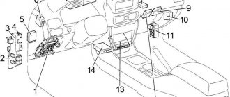
Salon
LHD
RHD
- Air conditioner control unit
- Fuse Box/Body Electrical Control Unit
- LHD:
Headlight range control unit - Steering lock control unit
- Power steering control unit
- Key transponder amplifier
- Relay block No. 1
- Relay block No. 2
- Distribution block
- Distribution block
- Wiper relay
- LHD:
Transmission control unit (Multi-mode) - Engine and gearbox control unit
- Start-stop system control unit
- Multimedia Interface Control Unit
- LHD:
Gearbox selector lock control unit - Airbag control unit
- RHD:
Turn signal relay
Fuse box in the passenger compartment
LHD |
RHD |
| № | Name | A | Purpose |
| 1 | AM1 | 7.5 | Starting system, multiport fuel injection system/sequential multiport fuel injection system, fuses: "CIG", "ACC" |
| 2 | FR FOG | 15 | Front fog light |
| 3 | — | — | — |
| 4 | ACC-B | 25 | Fuses: "CIG", "ACC" |
| 5 | DOOR | 25 | central locking |
| 6 | — | — | — |
| 7 | STOP | 10 | Brake Lamps, Auxiliary Brake Light, ABS, VSC, Body Electrical Control Module, Multiport Fuel Injection System/Sequential Multiport Fuel Injection System, Transmission Control Module |
| 8 | OBD | 7.5 | Diagnostic connector |
| 9 | ECU-IG NO.2 | 10 | Reversing lamps, charging system, auto-dimming interior mirror, monitor, sunroof, heated rear window, air conditioning, turn signals, hazard warning lights, front passenger seat belt indicator, start-stop system, park assist system |
| 10 | ECU-IG NO.1 | 10 | without start-stop system: Automatic headlight leveling, body electrical control unit, electric power steering, cooling fan(s), gearshift lock, rain sensor, ABS, VSC, audio system, navigation, multiport fuel injection system/sequential system multiport fuel injection, headlight cleaners, intelligent entry and start system |
| 11 | WASHER | 15 | Glass washer |
| 12 | — | — | — |
| 13 | WIPER | 25 | Windshield wiper, rain sensor |
| 14 | HTR-IG | 10 | Air conditioning, heated rear window, auxiliary heater |
| 15 | SEAT HTR | 15 | Heated seats |
| 16 | METER | 7.5 | Instrument cluster, start-stop system |
| 17 | IGN | 7.5 | Steering lock, airbags, transmission control module, multiport fuel injection system/sequential multiport fuel injection system, intelligent entry and start system, start-stop system |
| 18 | RR FOG | 7.5 | Rear fog light |
| 19 | — | — | — |
| 20 | — | — | — |
| 21 | MIR HTR | 10 | Heated mirrors, multiport fuel injection system/sequential multiport fuel injection system |
| 22 | — | — | — |
| 23 | ACC | 7.5 | Power mirrors, audio system, navigation, shift lock, body control module, intelligent entry and start system, start-stop system |
| 24 | C.I.G. | 15 | Cigarette lighter |
| 25 | SUNROOF | 20 | Luke |
| 26 | RR DOOR | 20 | Window lifters |
| 27 | RL DOOR | 20 | Window lifters |
| 28 | FR DOOR | 20 | Window lifters |
| 29 | ECU-IG NO.1 | 10 | with start-stop system: Automatic headlight leveling, body electrical control unit, electric power steering, cooling fan, gearshift lock, rain sensor, ABS, VSC, audio system, navigation, multiport fuel injection system/sequential multiport fuel injection system , headlight cleaners, intelligent entry and start system, start-stop system |
| 30 | PANEL | 7.5 | Light switch, instrument panel lights, glove box lights, steering wheel switches, body electrical control unit |
| 31 | TAIL | 10 | Side light, license plate light, rear fog light, front fog light, headlight range control, multiport fuel injection system/sequential multiport fuel injection system, instrument panel illumination |
LHD |
RHD |
| № | Name | A | Purpose |
| 1 | POWER | 30 | Front left window lifter |
| 2 | DEF | 30 | Heated rear window, fuse: “MIR HTR” |
| 3 | — | — | — |
| Relay | |||
| R1 | Ignition (IG1) | ||
| R2 | Jumper (automatic air conditioning) Heater (HTR) | ||
| R3 | LHD: Direction indicators | ||
Relay block in the cabin No. 1
| № | Relay |
| R1 | Starter (ST) |
| R2 | Rear Fog Light (RR FOG) |
| R3 | Auxiliary relay (ACC) |
| R4 | Auxiliary relay (ACC CUT) |
Relay block in the cabin No. 2
| № | Relay |
| R1 | Front fog light (FR FOG) |
| R2 | Starter (ST CUT) |
| R3 | Panel (PANEL) |
| R4 | — |
- Distribution block
- Window lifter control unit
- Central locking receiver
- Window lifter control unit
On the website avto-fresh.com you can find a diagram of fuses and relays for Toyota Corolla 150 (2006-2013), photos and descriptions of the blocks, as well as answers to questions about where it is located and what it is responsible for. The designation of electrical equipment is described in detail in the article.
Why does not it work
Before studying the cause of the breakdown, it is necessary to accurately determine that the cigarette lighter has actually failed. To do this you need to follow these steps:
- Turn on the car's ignition.
- Insert the cigarette lighter into the socket.
- After waiting 10-15 seconds, check the heating level. If the device barely warms up, then the problem really lies with it.
- At the end of the test, remove the device from the socket.
There may be several reasons for the breakdown. The heating coil may burn out if used frequently. In this case, it is necessary to completely replace it. This is the only thing that can happen directly to the cigarette lighter itself.
In other cases, you need to look for a problem in the electrical network. One of the most common problems is a blown fuse. The main reason for the failure of this element is connecting too much load. Many drivers connect portable coffee makers, compressors and other equipment. As a result, you will have to change the Toyota Corolla cigarette lighter fuse.
Signs may also include a clock or backlight not working. This indicates that there was a large power surge in the car, which is why some of the fuses have failed.
Rules for replacing fuses
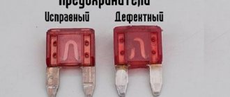
Differences between serviceable and faulty fuses and relays
The following factors can lead to the burnout of the protective element of the electrical circuit of the vehicle equipment:
- sudden change in voltage;
- short circuit;
- break.
Replacing the Toyota Corolla E150 fuse must be accompanied by preliminary elimination of the cause of its damage. To replace a burnt-out protective component, specialized plastic pliers should be used. They are included in the factory equipment and are located in the mounting block of the engine compartment.
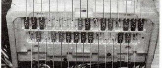
Special pliers for safe and convenient replacement of fuses. buried on the inside of the block cover.
When replacing a fuse, you will need to adhere to the following safety rules:
- 1) turn off the ignition and all electrical equipment;
- 2) the burned out element is replaced with one identical in terms of permissible current value;
- 3) it is strictly forbidden to use jumpers to replace damaged protective elements.
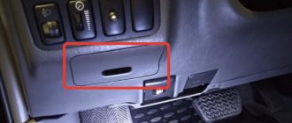
DIY Toyota Corolla cigarette lighter repair
When the Toyota Corolla cigarette lighter does not work, you can continue to drive the car, but comfort is significantly reduced. Even the driver does not use the cigarette lighter for its intended purpose, it has a lot of other useful functions - the hole is a source of energy to power additional devices. For example, chargers for a mobile phone or DVR. If it happens that the cigarette lighter stops working, you need to find out the cause of the breakdown and fix it. You can cope with this task yourself.
Cigarette lighter Toyota Corolla
