If your cigarette lighter fuse has blown or where the fuel pump relay is located, or you are simply looking for information on the location of the control units in your car. This article is dedicated to the Toyota Corolla 1995,1996,1997,1998,1999,2000,2001,2002 produced in the E110 body with ICE 4A-FE, 5A-FE, 7A-FE, 4E-FE, 2C-E 2C Left-hand drive ( LHD)
Right hand drive (RHD)
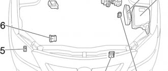
- Fuse Box / Integrated Relay
- Distribution block
- Relay block No. 1
- Fog light relay
- ABS control unit
- Key transponder computer
- Distribution block
- LHD:
Air Conditioner Booster - Daytime running light relay
- Central locking receiver
- Relay block No. 2
- O/D control unit
- 4A-FE, 5A-FE, 7A-FE, 4E-FE, 2C-E:
Engine control unit
2C:
Engine heater timer - Airbag central unit
- RHD:
Air Conditioner Booster (Mechanical Air Conditioner) - RHD:
Air Conditioner Booster (Automatic Air Conditioning) - RHD:
Central locking relay - RHD:
Gearbox selector lock control unit
Fuse box in the passenger compartment
| № | Name | A | Purpose |
| 1 | TURN | 7.5 | Direction indicators, hazard warning lights |
| 2 | — | — | — |
| 3 | GAUGE | 10 | Instrument cluster, reverse lights, air conditioning, power windows, heated rear window, central locking |
| 4 | WIP | 20 | Windshield wiper and washer |
| 5 | I/UP | 10 | Multiport fuel injection system/sequential multiport fuel injection system, mirror control unit |
| DEF I−UP/ M−HTR | 10 | Heated rear window, multiport fuel injection system/sequential multiport fuel injection system | |
| 6 | ECU-IG | 10 | Starting system, cooling fan, gear selector lock, ABS, cruise control |
| 7 | IGN | 7.5 | Multiport fuel injection system/sequential multiport fuel injection system, charging system, airbags, seat belt pretensioners |
| 8 | STOP | 15 | Brake lamps, additional brake lamp, ABS, gear selector lock |
| 9 | TAIL | 15 | Side lights, instrument cluster, instrument panel lights, license plate lights, cigarette lighter, clock, audio system, rear window defogger, automatic transmission control unit, multiport fuel injection system/sequential multiport fuel injection system, air conditioning, hazard lights |
| 10 | — | — | — |
| 11 | — | — | — |
| 12 | OBD | 7.5 | Diagnostic connector |
| 13 | ECU-B | 7.5 | LHD: Airbags, seat belt pretensioners, rear fog light |
| 5 | RHD: Airbags, seat belt pretensioners, rear fog light | ||
| 14 | ST | 5 | Starting system, multiport fuel injection system/sequential multiport fuel injection system |
| 15 | D/L | 30 | central locking |
| 16 | FOG | 15 | Fog light |
| 17 | S-HTR | 15 | Heated seats |
| 18 | — | — | — |
| 19 | C.I.G. | 15 | Audio system, clock, cigarette lighter , power mirrors, airbags, anti-theft system, seat belt pretensioners, gear shift lock |
| 20 | — | — | — |
| 21 | Noise Filter | — | Fuse: "DOME" |
| 22 | DEF | 40 | LHD: Heated rear window, fuse: ”DEF I−UP/M−HTR” |
| 30 | RHD: Rear window defogger, fuse: ”DEF I−UP/M−HTR” | ||
| 23 | POWER | 30 | Windows, sunroof |
| 24 | — | — | Jumper |
Location of the sunroof and rear wiper relay in the Corolla E110 sedan, station wagon, hatchback, liftback
Sedan
Liftback
Hatchback
Station wagon
- Sunroof relay
- Hatchback, Liftback:
Rear wiper relay - Estate (without Heater):
Rear wiper relay - Estate:
Rear Wiper Relay
How to control and replace fusible elements
The car owner can check whether the fuse is working or not using a multimeter. He must set the device knob to the “Diode” or “Ring” position.
Attention! The resistance measurement mode should be at the lowest point.
How is the operating state of a fusible contact determined:
- if the part is working, then the resistance will always show 0;
- if the element burns out, the car owner will see a unit on the multimeter display.
Once the car owner has discovered that the fuse is not working, it needs to be replaced.
How to change them
Experts recommend replacing fuses with the same rating. Or use fusible elements with a rating of up to 40 percent higher than required. Only in this case will the part burn out in time before the heat spreads throughout the wiring and causes a fire.
Experienced mechanics do not recommend installing paper clips, bugs and other devices that are homemade and unreliable. Not only will they not prevent a fire, but they can also cause the entire vehicle to catch fire.
When replacing, you need to pay attention not to one contact, but to the whole contact group. If the block is worn out or destroyed, then it is necessary to replace the group of fusible elements.
To change the contact you do not need to buy special tools. Experienced mechanics use regular tweezers to remove the fuse from its socket. Based on the current strength, a beginner will also not be able to confuse the parts. Since each of them is painted in its own color. Of course, you only need to install a part of the same color in one slot.
The blocks are covered with plastic covers. It will not be difficult for the car owner to take them off and put them on again.
Attention! Modern modifications of the Toyota Corolla have complicated fusible element block diagrams. Therefore, it is not recommended for a beginner to do this himself.
Replacement procedure:
- Open the hood of the vehicle and remove the cover from the fusible unit, which is located next to the radiator.
- Or sit in the driver's or passenger's seat (depending on the location of the required part) and reach the air vent grille.
- Take it off. Open the block with fusible elements.
- Use tweezers to remove the burnt one that needs to be replaced.
- Insert new one.
- Start the engine. Check whether the devices for which the part is responsible are working.
Attention! All work must be done with the ignition off.
Fuse box in the engine compartment of Corolla E110
| № | Name | A | Purpose |
| 1 | ALT-S | 5 | Charging system |
| 2 | HEAD (RH) | 10 | without DRL: Right headlight |
| HEAD (RH-UPR) | 10 | with DRL: Right headlight ( DRL - daytime running lights) | |
| 3 | EFI | 15 | 4A-FE, 5A-FE, 7A-FE, 4E-FE: Multiport fuel injection system/sequential multiport fuel injection system |
| F-HTR | 15 | 2C-E: Multiport fuel injection system/sequential multiport fuel injection system | |
| 4 | HORN | 10 | Horn, anti-theft system |
| 5 | HAZARD | 10 | Hazard warning lights, direction indicators |
| 6 | AM2 | 15 | Starting system, fuses: ”ST”, ”IGN” |
| 7 | — | — | — |
| 8 | HEAD (LH) | 10 | without DRL: Left headlight |
| HEAD (LH-UPR) | 10 | with DRL: Left headlight ( DRL - daytime running lights) | |
| 9 | DOME | 15 | Audio system, interior lighting, personal lighting, trunk lighting, clock, daytime running lights, anti-theft system |
| 10 | — | — | — |
| 11 | — | — | — |
| 12 | — | — | — |
| 13 | — | — | — |
| 14 | AM1 | 50 | Fuses: "CIG", "TURN", "GAUGE", "ECU-IG", "WIP" |
| 15 | FAN | 30 | Cooling fan |
| RDI | 30 | Cooling fan | |
| 16 | MAIN | 40 | Starting system, fuses: "HEAD (LH) or HEAD (LH−UPR), "HEAD (RH) or HEAD (RH−UPR), "HEAD LH−Lo" and "HEAD RH−LO" |
| 17 | ALT | 100 | Fuses: "RDI", "CDS", "AM1", "POWER", "D/L", "TAIL", OBD, "FOG", "ECU-B", "STOP", "DEF", "HTR" ” |
| 18 | ABS | 50 | ABS |
| Relay | |||
| R1 | Engine control unit (ENGINE MAIN) | ||
| R2 | 4A-FE, 5A-FE, 7A-FE, 4E-FE: Engine control unit (EFI) 2C-E: Fuel heater (F-HTR) | ||
| R3 | Headlights (HEAD) | ||
| R4 | Starter (ST) | ||
| R5 | Sound signal | ||
| R6 | Cooling fan (FAN NO.1) | ||
Blocks in the cabin
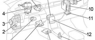
General location
Scheme
Description
- 4 - door lock control relay
- 5 - relay and fuse block No. 4
- 6 - fuse block No. 1
- 7 - relay block
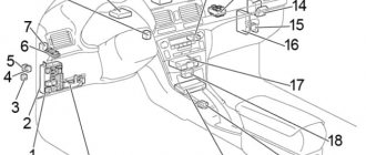
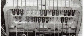
Fuse and relay block No. 1
In the diagram they are designated as 6 and 7 and are located under the instrument panel on the left pillar in its lower far part.
It is closed with a protective cover, on the reverse side of which there will be your current diagram.
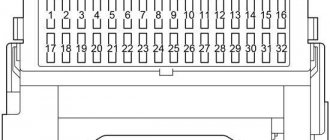
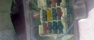
Example block
Diagram
Assignment of fuses
Right hand drive
| 1 | 15A FOG - fog lights |
| 2 | 10A IGN - ignition |
| 3 | 15A STOP - brake lights |
| 4 | 30A DEFOG - glass heater |
| 5 | 20A CIG & RADIO - cigarette lighter, radio, mirrors |
| 6 | 10A ECU-B - ABS, power supply for central locking |
| 7 | 10A TURN - direction indicators |
| 8 | 10A GAUGE - devices |
| 9 | 15A TAIL - dimensions |
| 10 | 7.5A DEF-I/UP - increasing idle speed when the glass defroster is turned on |
| 11 | 15A ECU-IG - transmission electronics, ABS, control system lock (automatic transmission) |
| 12 | 20A WIPER - windshield wipers |
Left hand drive
| 1 | 15A FOG - fog lights |
| 2 | 10A IGN - ignition |
| 3 | 15A STOP - brake lights |
| 4 | 20A SEAT HTR - seat heater |
| 5 | 20A CIG & RADIO - cigarette lighter, radio, mirrors |
| 6 | 10A ECU-B - ABS, power supply for central locking |
| 7 | 10A TURN - direction indicators |
| 8 | 10A GAUGE - devices |
| 9 | 10/15A TAIL - dimensions |
| 10 | 7.5A DEF-I/UP - increasing idle speed when the glass defroster is turned on |
| 11 | 15A ECU-IG - transmission electronics, ABS, control system lock (automatic transmission) |
| 12 | 20A WIPER - windshield wipers |
Fuse number 5 at 20A is responsible for the cigarette lighter.
Relay designation
- a — POWER — glass lifts, sunroof and central locking
- b — FOG — fog lights
- c - FLASHER - relay - breaker
- A - DEFOG - glass heater
- B - TAIL - dimensions
Relay and fuse block No. 4
Scheme
Description
- 40A HEATER - Heater
- 15A A/C - Air conditioning
- A - Heater relay
The first relay block under the hood
In the configuration without daytime running lights, relay R1 is missing!
| № | Name | A | Purpose |
| 1 | CDS | 30 | Cooling fan |
| 2 | HEAD (LH-LWR) | 10 | with DRL: Left headlight ( DRL - daytime running lights) |
| 3 | HEAD (RH-LWR) | 15 | with DRL: Right headlight |
| 4 | DRL | 7.5 | Daytime Running Lights |
| Relay | |||
| R1 | Dimmer | ||
| R2 | Cooling fan (AC FAN NO.2) | ||
| R3 | Cooling fan (AC FAN NO.2) | ||
| R4 | Air Conditioning Compressor Clutch (AC MG) | ||
Fuses and relays Toyota Corolla 100
Cars considered: Toyota Corolla 100, Toyota Corolla Levin, Toyota Sprinter Trueno, Toyota Corolla Ceres, Toyota Sprinter Marino sedan, hatchback, station wagon produced in 1991, 1992, 1993, 1994, 1995, 1996, 1997, 1998, 1999, 2000.
Fuse and relay box in the engine compartment.
Component location.
1 - relay and fuse block No. 5-1 (Europe), 2 - relay and fuse block No. 2, 3 - relay and fuse block No. 5-1, relay and fuse block No. 5-2 (Europe)
Layout of fuses and relays in block No. 2.
There is a number 2 in the image above.
Decoding.
Right-hand drive models.
| Circuit breakers | ||
| A | AM2 (circuit AM2 of the ignition switch (terminals IG2, ST2) | 30A |
| b | FAN (radiator fan) | 30A |
| With | AM1 (output circuit AM1 of the ignition switch (terminals ACC, IG1, ST1) GLOW (diesel) | 40A 80A |
| d | ALT (gasoline) (charging) AM1 (diesel) AM1 (2E) | 100A 80A 60A |
| e | ABS | 50A |
| 1 | DOME (electric drive and interior lighting) | 20A |
| 2 | HA7-HORN (hazard warning, horn) | 20A |
| 3 | FAN-I/UP (idle boost) | 7.5A |
| 4 | ALT-S (charging) | 7.5A |
| 5 | spare | 7.5A |
| 6 | spare | 15A |
| 7 | spare | 20A |
| 8 | HEAD (RH) (right headlights) | 15A |
| 9 | HEAD (LH) (left headlights) | 15A |
| 10 | EFI F-HTR | 15A |
| Relay | ||
| A | HORN (horn) | |
| IN | FAN (radiator fan) | |
| WITH | E/G-MAIN (main relay) | |
| D | HEAD (headlights) | |
| E | EFI (fuel injection system) | |
Right-hand drive models.
| Circuit breakers | ||
| A | AM2 | 30A |
| b | FAN | 30A |
| With | AM1 | 40A |
| c | GLOW (diesel) | 80A |
| d | ALT (gasoline) | 100A |
| d | AM1 (diesel) | 80A |
| d | AM1 (2E) | 60A |
| e | ABS | 50A |
| 1 | DOME | 20A |
| 2 | HAZ-HORN | 20A |
| 3 | — | |
| 4 | ALT-S | 7.5A |
| 5 | spare | 7.5A |
| 6 | spare | 15A |
| 7 | spare | 20A |
| 8 | DRL | 7.5A |
| 9 | — | |
| 10 | EFI F-HTR | 15A |
| Relay | ||
| A | HORN | |
| IN | FAN | |
| WITH | E/G-MAIN | |
| D | HEAD | |
| E | EFI | |
Relay and fuse box No. 5-1 Toyota Corolla (100 body).
In the image (Europe) the number 3 is right-hand drive.
Fuse Box No. 5-2 (Europe)
In the image
Fuse box in the interior of a Toyota Corolla 100.
Arrangement of components in the cabin.
4 - door lock control relay, 5 - relay and fuse block No. 4, 6 - fuse block No. 1, 7 - relay block.
Layout of fuses and relays in block No. 1 located in the cabin.
The image above is number 6.
Purpose.
Right-hand drive models.
| Circuit breakers | ||
| A | POWER (windows, sunroof and central locking) | 30A |
| b | — | |
| 1 | FOG (fog lights) | 15A |
| 2 | IGN (ignition) | 10A |
| 3 | STOP (stop lights) | 15A |
| 4 | DEFOG (defroster glass) | 30A |
| 5 | CIG & RADIO (cigarette lighter and radio) | 20A |
| 6 | ECU-B (ABS, central locking power supply) | 10A |
| 7 | TURN (turn signals) | 10A |
| 8 | GAUGE (devices) | 10A |
| 9 | TAIL (dimensions) | 15A |
| 10 | DEF-I/UP (increasing idle speed when the defroster is turned on) | 7.5A |
| 11 | ECU-IG (transmission electronics, ABS, control system lock (automatic transmission) | 15A |
| 12 | WIPER (windshield wipers) | 20A |
| Relay | ||
| A | — | |
| IN | TAIL (dimensions) | |
Left-hand drive models.
| Circuit breakers | ||
| A | POWER | 30A |
| b | DEFOG | 30A |
| 1 | FOG (kr, Germany) | 15A |
| 1 | TAIL (LH) (Germany) | 10A |
| 2 | IGN | 10A |
| 3 | STOP | 15A |
| 4 | SEAT HTR | 20A |
| 5 | CIG & RADIO | 20A |
| 6 | ECU-B | 10A |
| 7 | TURN | 10A |
| 8 | GAUGE | 10A |
| 9 | TAIL (Germany) | 15A |
| 9 | TAIL (Germany) | 10A |
| 10 | DEF-I/UP | 7.5A |
| 11 | ECU-IG | 15A |
| 12 | WIPER | 20A |
| Relay | ||
| A | DEFOG (defroster glass) | |
| IN | TAIL (dimensions) | |
Relay and fuse box No. 4.
In the image
Relay block.
In the image
Kinds
There are three types of fuses:
- Type A.
- Type B.
- Type C.
Each of them looks different, and fuse failures are characterized differently.
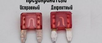
Details of the first type can be seen in more detail in the following picture.
Here you can clearly see that the Toyota Corolla fuse on the left is intact, and the fuse on the right is blown.
The second type looks different; you can examine its integrity not from the side, but from above. The picture shows which fuse is intact and which is not.
Type C products burn out internally. The picture shows how this happens.
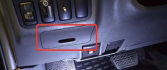
Fuse box next to passenger's foot (left-hand drive)
1 - A/C (15A) - air conditioning system, fan 2 - HTR M (40A) - heater fan A - heater relay
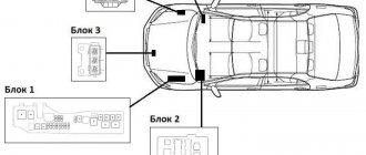
Location of fuse blocks and decoding for Toyota Corolla 120 body
Location of fuse boxes.
In the Toyota Corolla vehicle in the E120 body there are five mounting blocks, which are located both in the engine compartment and in the vehicle interior. Finding these blocks is quite easy if you know where to look.
Another diagram of the location of fuse blocks
Fuse block No. 1
The first fuse box is located on the left side of the engine compartment. The lid is held on by latches that are fairly easy to remove. In addition to fuses, this block contains control relays.
Let's look at the decoding of the fuses and relays of the first block of the Toyota Corolla E120:
Replacing fuses
Before carrying out prevention, we prepare:
- A set of new blade type fuses;
- Screwdriver;
- Additional lighting;
- Ratchet, head “10” for dismantling the block assembly;
- Plastic tweezers for removing modules.
The sequence of actions when independently replacing modules in the Mercedes Sprinter interior:
- Open the driver's door, lock the car on the parking brake, turn off the ignition;
- There is a mounting block under the steering wheel. We snap off the plastic cover and use tweezers to remove the faulty module by serial number;
- We insert a new fuse into its original place and close the cover.
If it becomes necessary to install the block assembly, you must additionally unscrew the two fasteners with a screwdriver, disconnect the connectors with wires, then remove the board and replace it with a new one.
To install new modules on the stove heater, you need to move the driver's seat back all the way. A mounting block with modules for a stove heater is installed in the cavity of the chair base.
Carefully unclip the cover, find the module by serial number, and remove it. We insert a new one in place of the faulty one, close the lid again, and adjust the seat.
Unlike fuses, relay breakers have a longer service life and need to be replaced less frequently. Mainly after accidents, collisions, or mechanical damage.
Check the mounting block for moisture after long trips through puddles. Dry, blow with compressed air as necessary. Do not allow condensation to accumulate in the housing.