Toyota Avensis 2nd generation has code T25 / T250 and was produced in 2003, 2004, 2005, 2006, 2007, 2008 and 2009. In this article you will find information with the locations of all electronic control units, a detailed description of the fuses and relays of the Toyota Avensis 2 with block diagrams and photo examples of their implementation. Let's highlight the cigarette lighter fuse separately.
The design of the blocks and their location may differ from that presented and depends on the year of manufacture, level of equipment and region of delivery.
Electrical Wiring Diagram Toyota Avensis 2003-2009
| Data | ||
| Dimensions and Weight | ||
| 1 | Length | 4630-4645 |
| 2 | Width (without/with mirrors) / Width | 1760 |
| 3 | Height (loaded/empty) / Height | 1480 |
| 4 | Wheelbase | 2700 |
| 5 | Ground clearance | 135-155 (Rough Road Package) |
| 6 | Curb weight / Total (curb) weight | 1375-1420 |
| Gross (max.) weight | 1905 | |
| Engine | ||
| 7 | Type / Engine Type, Code | Gasoline, liquid cooling, four-stroke, 2AZ-FSE |
| 8 | Number of cylinders / Cylinder arrangement: Total number of cylinders, of valves | 4-cylinder, 16V, in-line, DOHC DOHC |
| 9 | Cylinder Diameter/Bore | 88.5 mm |
| 10 | Piston stroke/Stroke | 96.0 mm |
| 11 | Volume / Engine displacement | 2362 cm³ |
| 12 | Power supply system / Fuel supply, Aspiration | Multiport fuel injection D-4 EFI |
| Atmospheric | ||
| 13 | Compression ratio | 11.0:1 |
| 14 | Maximum power / Max. output power kW (HP) at rpm | 120 kW (163 hp) at 5800 rpm |
| 15 | Maximum torque / Max. torque N m at rpm | 230 Nm at 4000 rpm |
| Transmission | ||
| 16 | Clutch type | Torque converter, lockable |
| 17 | Gearbox / Transmission type | U151E Automatic transmission 4 Automatic, four-speed, adaptive |
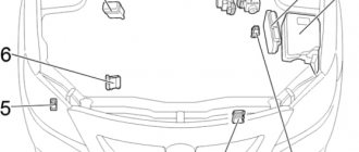
Blocks in the cabin
Location
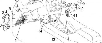
General layout of electronic control units in the cabin
Left steering
Right hand steering
General designation
- Fuse box
- Integrated relay
- Fuel Pump Relay (Circuit Opening)
- Rear fog light relay
- Heated rear window relay
- Relay block
- Turn signal relay
- Key transponder amplifier
- EPS ECU
- Key transponder control unit
- Antenna amplifier
- Distribution block
- Wiper relay
- Central locking receiver
- Headlight range control unit
- Engine and transmission control unit (A/T) Engine control unit (M/T)
- Air conditioner control unit
- Optional connector (navigation)
- Gearbox selector control unit
- Airbag control unit
- Navigation control unit
- Additional fuse block
- RHD:
Anti-theft control unit
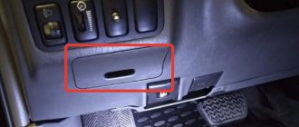
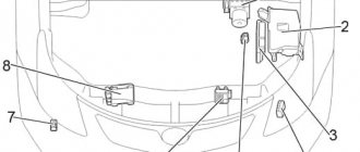
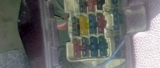
Fuse box
It is located at the bottom of the instrument panel behind the protective cover.
Photo - example
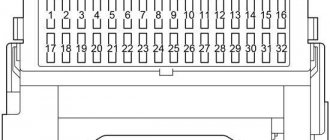
Scheme
Description
| 1 | 10A IGN - SRS airbags, instrument cluster, starting system, multiport fuel injection system / sequential multiport fuel injection system |
| 2 | 20A S/ROOF - Hatch |
| 3 | 7.5A RR FOG - Rear fog light |
| 4 | 15A FR FOG - Front fog light, fog light indicator |
| 5 | 25A AM1 - Starting system, fuses: “CIG”, “RAD NO.1” |
| 6 | 7.5A PANEL - Instrument panel lights, instrument cluster lights, automatic transmission control unit, glove box lights, armrest lights, headlight cleaners, front fog lights, parking assist, multi-information display |
| 7 | 20A RR WIP - Rear wiper and washer |
| 8 | 7.5A GAUGE2 - Reversing lamps, headlight range control, turn signals, hazard warning lights |
| 9 | 15A CIG - Cigarette lighter |
| 10 | 10A HTR - Heated seats, air conditioning |
| 11 | — |
| 12 | 7.5A RAD NO.1 - Audio system, multi-information display, power mirrors, instrument cluster, power outlet |
| 13 | 30A PWR SEAT - Electric seats |
| 14 | 10A TAIL - Parking light, license plate light, trunk light, automatic light system, front fog light, rear fog light, instrument cluster |
| 15 | 7.5A OBD2 - Diagnostic connector |
| 16 | 15A P/POINT - Outlet |
| 17 | 25A DOOR - Central locking |
| 18 | 25A WIP - Front wiper and washer, headlight cleaners |
| 19 | 7.5A ECU-IG - Cooling Fan, Charging System, Power Steering, ABS, VSC |
| 20 | 20A S-HTR — Heated seats |
| 21 | 10A GAUGE1 - Light switch, multi-information display, integrated relay, instrument cluster, gearshift lock, automatic transmission control unit, interior rear view mirror, windshield wiper, parking brake |
| 22 | 15A STOP - Stop Lamps, Shift Lock, Auxiliary Brake Lamp, Multiport Fuel Injection System/Sequential Multiport Fuel Injection System |
| Relay | |
| R1 | Reserve |
| R2 | HTR - Heater |
| R3 | SEAT HTR - Heated seats |
| R4 | IG1 - Ignition |
| R5 | TAIL - Side light |
Fuse number 9 at 15A is responsible for the operation of the cigarette lighter.
Additional fuse block
Located above the pedals, parallel to the floor.
Scheme
Purpose
| 1 | 25A ACC Start button, immobilizer, steering wheel lock (LHD) |
| 2 | 20A P-RR P/W - Window lifter |
| 3 | 20A P-FR P/W - Window lifter |
| 4 | 20A D-RR P/W - Window lifter |
| 5 | 20A D-FR P/W - Window lifter |
| 6 | 7.5A ECU-B 1 - Transmission |
| 7 | 10A FUEL OPN - Fuel filler flap |
| 8 | 20A FR DIC - Windshield wiper heater, fuse: “MIR HTR” |
| 9 | 10A A/C Air conditioning (mechanical air conditioning), auxiliary heater |
| 10 | 7.5A DEF I/UP - Air Conditioning |
| 11 | 7.5A ST - Multi - Information Display, Multiport Fuel Injection System/Sequential Multiport Fuel Injection System, Starting System |
| 12 | 10A MIR HTR — Heated mirrors |
| 13 | 15A RAD NO.2 - Audio system, multi - information display |
| 14 | 7.5A DOME - Interior Lighting, Personal Lighting, Door Lighting, Trunk Lighting, Personal Mirror Lighting, Footwell Lighting |
| 15 | 7.5A ECU-B 2 - Air conditioning, wireless control system |
| 16 | 30A PWR SEAT - Electric seats |
Relay block
Scheme
Left hand drive
Right hand drive
Decoding
- R1 - Heater for windshield wiper blades (FR DEICER)
- R2 - Socket (P/POINT)
- R3 - Front fog light (FR FOG)
- R4 - Starter (ST)
Additional items
Scheme
Purpose
- Phone microphone amplifier
- Sunroof control unit
- Rear wiper relay
Toyota Avensis Verso/Picnic 2001-2009 Electrical Wiring Diagrams
ELECTRICAL WIRING SYSTEM 1. RELAY Symbol used to identify a relay. 2. CONNECTOR 1 The sketch of this connector shows that this connector is a single-pole connector. 3. CONNECTING WIRES Some electrical diagrams are placed on several sheets for ease of use. Where necessary, the purpose of the wires is indicated by the corresponding symbol. (If two pages are required for exact specification) 4. FUSE NUMBER AND RATING “FUSE NUMBER AND RATING” corresponds to that used in the unit (main fuse box, fuse box and junction box).
5. CONNECTOR • Each connector is represented on the diagram by a corresponding symbol. • The designation of each terminal is shown in abbreviated form on the corresponding diagram. • For example, terminal number “G4” corresponds to terminal number 4 of the connector (G: F41) shown in the connector sketch. 6. CONNECTOR DESIGN • The sketch of each connector must indicate the shape and color of the connector, as well as the location of its terminals. Unpainted connectors are designated white or natural color. • When more than two connector numbers are shown on a connector sketch, it means that both types of connectors can be used.
7. MOUNT The location of each ground point can be easily determined by the corresponding wiring harness. 8. DIODE Symbol used to represent a diode. 9. MARKING OF THE WIRE WHEN IT TRANSITIONS TO ANOTHER SHEET OF THE CIRCUIT On electrical diagrams placed on more than one sheet, the transition of the wire to another sheet is indicated by an arrow located next to the letter designation of the wire. 10. SYMBOLS FOR DESIGNATION OF CONNECTIONS AND WIRES CROSSINGS ON THE ELECTRICAL DIAGRAM 11. POWER SUPPLY CIRCUIT On each electrical diagram, the power source is shown by a certain symbol. The designations “MB-5”, “MB-6”, etc. used in the text correspond to those shown in the electrical diagram in the “DC POWER CIRCUIT” section. Accordingly, with the help of the “DC POWER CIRCUIT” section and electrical diagrams, plant personnel can understand the layout of the entire system. 12.CLASSIFICATION BY SPECIFICATION When electrical circuits differ depending on vehicle specification, the difference is indicated by abbreviations.
This supplement provides information covering changes in the electrical system specifications of the AVENSIS VERSO / PICNIC which were made in October, 2003.
loveavto — Toyota Avensis
Technical documentation for repair of Toyota Avensis cars (all years of production) Free, without registration and SMS
Toyota Avensis Repair, Operation and Maintenance Manual
- full technical specifications
- operating features
— troubleshooting Toyota Avensis
— color wiring diagrams of Toyota Avensis DOWNLOAD / DOWNLOAD FROM THE MIRROR
Toyota Avensis Operation Manual - full technical specifications Toyota Avensis - operating features
- trouble-shooting
— colored electrical circuits DOWNLOAD / DOWNLOAD FROM THE MIRROR
Toyota Avensis repair manual in photographs - full technical specifications
- operating features of Toyota Avensis - troubleshooting in photographs with your own hands - more than 1980 photographs of the repair process DOWNLOAD / DOWNLOAD FROM THE MIRROR
Catalog of parts and assembly units of Toyota Avensis - table of interchangeability of car parts
— intended for service station workers and owners of Toyota Avensis cars — Toyota Avensis parts catalog DOWNLOAD / DOWNLOAD FROM THE MIRROR
Detailed electrical diagram of Toyota Avensis - a complete description of the electrical equipment of Toyota Avensis, a detailed interactive electrical diagram of Toyota Avensis - the algorithm for troubleshooting electrical equipment (starter, generator, ignition system, injection, injector) is described in detail - detailed diagram of electrical equipment (electrical diagram) Toyota Avensis - pinout of electrical connectors , electrical wiring pinout for Toyota Avensis DOWNLOAD / DOWNLOAD FROM THE MIRROR
Toyota Avensis engine repair manual - full technical specifications of the Toyota Avensis engine - design and repair features of the Toyota Avensis engine - detailed description of the processes of disassembling, troubleshooting and assembling the engine with photographs, timing belt DOWNLOAD / DOWNLOAD FROM THE MIRROR
Repair manual for Toyota Avensis gearboxes - full technical characteristics of the gearbox - design and repair features of the Toyota Avensis gearbox - troubleshooting gearboxes, transmission, shafts, gears, CV joints - detailed description of the processes of disassembling, troubleshooting and assembling the gearbox with photographs DOWNLOAD / DOWNLOAD FROM THE MIRROR
but here you can earn money for a new car, and then you won’t have to repair the old one!!!
Toyota Avensis
Procedure for replacing a Toyota radio fuse
Any on-board system, being in practice an ordinary electrical circuit, must have a block of circuit breakers or, as it would be more correct to put it in the case of cars, fuses. Many drivers, who do not have a good understanding of the equipment of the car, do not attach importance to replacing the automatic equipment when the devices fail.
Radio in Toyota
Meanwhile, in leading brands, it is the fuse block that not only protects the on-board system from failure, but also requires constant preventive inspection and replacement of damaged elements. Most often, the radio fuse of Toyota Corolla and other brands suffers due to the cigarette lighter.
Toyota Avensis Service Manual - electrical diagrams
Toyota Avensis ZZT250, ZZT251, AZT250, CDT250 series General information
Headlight adjustment
Vehicles with dynamic suspension
1. Adjust the suspension to your normal driving height. Refer to owner's literature. All cars
2. Place the vehicle on a level, level surface.
3. Make sure the tire pressure is within specifications and there is no abnormal vehicle load.
4. Use the headlight leveling system several times, and then set the headlight leveling switch to position 0.
5. Turn on low beam headlights.
6. Install the equipment measuring screen to adjust the direction of the light to a position that corresponds to the correct adjustment of the headlights.
7.Adjust the headlights so that the limit line touches the horizontal line.
8. Some of the diffuse low beam headlights may be above the 15 degree line.
After adjusting the horizontal axis, you may need to adjust the vertical axis further.
Adjust the headlights so that the lift line of the limit line is at the intersection of the horizontal line and the 15 degree line (left-hand drive vehicle shown).
FIND SHORT CIRCUIT
(a) Remove the blown fuse and turn off all fuses.
(b) Connect a test lamp in place of the fuse.
(c) Set the conditions under which the indicator lamp lights up.
Example:
[A] - ignition on SW
[B] - ignition SW and SW 1 are on
[C] - ignition is on SW, SW 1 and relay (relay connection) and SW 2 are off (or turn off SW 2)
(d) Disconnect and reconnect the connectors while looking at the indicator lamp. There is a short circuit between the connector where the indicator lamp is on and the connector where the lamp goes out.
(e) Find the exact location of the short circuit by gently shaking the problem wire along the body.
ATTENTION:
(a) Do not open the ECU cover or housing unless absolutely necessary. (If the IC pins are connected, the IC may be destroyed by static electricity.)
(b) When replacing the internal mechanism (ECU part) of the digital meter, be sure that no part of your body or clothing touches the IC terminals, etc. of the spare part.
Toyota Avensis Repair Manuals
Collection of maintenance and repair instructions for Toyota Avensis
Publisher: Toyota Motor Corporation
Toyota Avensis AZT250, ZZT250, ZZT251, CDT250 series
Wiring Diagrams 526 and 625 - Download PDF
Toyota Avensis 2003-2009 EWD 526E Electrical diagrams Download pdf
How to remove a Toyota Avensis headlight - Headlight regeneration - removal
.
Replacing fuses yourself
The simplicity of the structural arrangement of both fuse blocks makes it easy to replace faulty fuses even if the car breaks down on the highway.
The entire scope of work on servicing the electrical part of the vehicle does not require professional skills in car repair and will only take 15-20 minutes of free time.
The only tools needed to replace fuses on a Toyota Avensis are a flat-blade screwdriver and pliers, or a special puller for dismantling parts.
The procedure for replacing damaged fuses follows the following algorithm:
- To begin with, it is imperative to provide power to the vehicle - it will be enough to disconnect both terminals from the car battery. Remember, replacing fuses while the battery is connected to the main power supply circuit can lead to voltage surges, which will lead to failure of the fuses themselves or even the equipment of the car, which will significantly increase the cost of servicing the car;
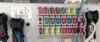
- Next, after dismantling the terminals or battery, you need to find the fuse box under the hood - on cars oriented for the European market, the part is located on the right side of the engine. To dismantle the cover on the fuse box, you will have to unclip the locking pins using a slotted screwdriver. In this case, it is necessary not to damage the latches - otherwise the fuse box will no longer be sealed;
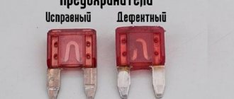
- Then we visually inspect all fuses and identify faulty ones. Defeated elements will have traces of melting on the body, and will also have a cracked passage plate;
- We dismantle the damaged elements using a special puller or ordinary pliers, after which we install a new element into the seating cell, pressing lightly until a characteristic click appears;
- After successful replacement, we close the unit with plastic latches and go to the vehicle interior to replace the internal unit. The interior unit is located on the left side of the steering wheel and is designed to protect equipment modules included in the vehicle from overvoltage;
- When completing the maintenance procedures, we reconnect the battery and check the functionality of all functions in the car.
It is important to know! It is strictly not recommended to connect fuses with a higher rated power to the system than allowed from the factory - such a replacement seriously reduces the effectiveness of protecting the vehicle from overvoltage and can cause failure of the vehicle’s electrical equipment and costly repairs in the near future.
Don’t skimp on fuses and have all your car’s electrical systems serviced in a timely manner – this will significantly increase the life of your car.
Electrical diagrams TOYOTA AVENSIS - Car electrical wiring diagram
Electrical connection diagram TOYOTA AVENSIS
TOYOTA AVENSIS brake light connection diagram
TOYOTA AVENSIS - Starting diagram
TOYOTA AVENSIS charger connection diagram
Connection diagram for the TOYOTA AVENSIS ignition system
TOYOTA AVENSIS engine control wiring diagram
Connection diagram for door lock control system and anti-theft system TOYOTA AVENSIS
TOYOTA AVENSIS wiring diagrams are above the page.
The Toyota Avensis replaced the Carina in 1997. Production of first generation cars continued until 2003.
The Avensis came in sedan, hatchback and estate versions (which was a separate Caldina ). For the car there were three petrol engines 1.6, 1.8 and 2.0, as well as a two-liter turbodiesel.
The second generation Toyota Avensis (2003-2008), as before, was produced with the same body types at a plant in the UK, from where the cars were delivered, including to the Japanese market.
Avensis sedans and station wagons were sold in 1.8 L (129 hp), 2.0 L (147 hp) and 2.4 L and 163 hp. In Europe, in addition, there were versions with a 1.6-liter engine. gasoline engine and with diesel engines 2 and 2.2 liters. Japanese buyers were offered cars with 2.0 or 2.4 petrol engines, including all-wheel drive.
.
% PDF-1.6 % 324 0 object > endobj xref 324 54 0000000016 00000 n. 0000002171 00000 n. 0000002277 00000 n. 0000002427 00000 n. 0000002705 00000 n. 0000002841 00000 n. 0000003136 00000 n. 0000003282 00000 n. 0000003605 00000 n. 0000003683 00000 p. 0000005387 00000 p. 0000005537 00000 n. 0000005712 00000 n. 0000005850 00000 n. 0000006266 00000 n. 0000006543 00000 n. 0000006907 00000 n. 0000007165 00000 n. 0000007653 00000 n. 0000007789 00000 n. 0000008313 00000 n. 0000008559 00000 n. 0000008944 00000 n. 0000009184 00000 p. 0000016332 00000 p. 0000032528 00000 p. 0000032786 00000 p. 0000033202 00000 p. 0000047473 00000 p. 000007461 4 00000 p. 0000094211 00000 p. 0000094450 00000 p. 0000094902 00000 p. 0000116671 00000 n. 0000121012 00000 n. 0000126413 00000 n. 0000132011 00000 n. 0000135104 00000 n. 0000139809 00000 n. 0000140043 00000 n. 0000140353 00000 n. 0000140707 00000 n. 0000144037 00000 n. 0000144274 00000 n. 0000158571 00000 n. 0000158829 00000 n. 0000159153 00000 n. 0000159509 00000 n. 0000171409 00000 n. 0000171667 00000 n. 0000188360 00000 n. 0000188637 00000 n. 0000189029 00000 n. 0000001376 00000 n. trailer ] >> startxref 0 %% EOF 377 0 object > flow xb«f« = Ab, 4, ztl $ f85-oΝj: 3Ӂ00 | Lp dcM2)>8 = (sˮnV0Gi] Bb * | {wNI->S "7 [佹 lW_Yԫ6lmΊ%; 9EEonNWp 梣 g $ n6jiN:
R * 6} u R \ OGP6y =
.
The car won't start - is the starter to blame?
Problems with the starter arise gradually. The car stops starting the first time, while making a characteristic sound. You should check the serviceability of the starter after the car fails to start two or three times the first or second time. If the car does not start the first time, the problem may not only be with the starter. It may be in the spark plugs or in the starter relay, in the ignition switch contact group, in the retractor or in the brush assembly. Before deciding to replace the starter, you should check these machine systems. If the problem is found to be due to these reasons, they should be addressed first. But what if the problem is the starter relay?
Toyota repair shop | Operating Instructions (100% Free)
- Find repair manual
- Ask the Experts
- Car Repair Blog
- About Us
Select Select manufacturer
- A.C.
- Abarth
- Acura
- Aixam
- Alfa Romeo
- Alpina
- Alpine
- Aro
- Artega
- Asia
- Asia Motors
- Aston Martin
- Audi
- Austin
- Austin Healy
- BAIC
- BAIC Huansu
- BAIC Senova
- BAIC Weiwang
- BAW
- BMW
- BYD
- Baojun
- Bedford
- Beijing
- Bentley
- Bisu
- Borgward
- Shine
- Bristol
- Bugatti
- Buick
- CHTC
- Cadillac
- Hana
- Changfeng
- Changan
- Changgon
- Changhe
- Chery
- Chevrolet
- Chrysler
- Citroen
- Cizeta
- Corvette
- Cowin
- D.S.
- Dacia
- Dadi
- Daewoo
- Daihatsu
- Daimler
- Datsun
- De Lorian
- De Tomaso
- DeTomaso
- Derways
- Dodge
- DongFeng
- Donkervoort
- Igli
- FAW
- FSO
- Ferrari
- Fiat
- Fisker
- Ford
- Fuqi
- GEO
- GMC
- Geely
- Being
- Gonov
- Great Wall
- Grekav
- Groz
- Gumpert
- Hafei
.TOYOTA electrical diagrams
Toyota Avensis Repair and Service Manuals (35 PDF files)
We have 35 Toyota Avensis Manuals covering a total of 21 years of production. In the table below you can see 0 Avensis Repair Manuals, 0 Avensis Service Manuals and 2 miscellaneous Toyota Avensis Downloads.
Our most popular manual is the Toyota Avensis 1998-2002 Service Repair Manual PDF. This (like all our guides) is free to download in PDF format.
How to download Toyota Avensis Repair Manual (for any year)
These Avensis manuals are provided by our users, so we cannot guarantee completeness. We have checked the years that are listed in the manuals and we have Toyota Avensis repair manuals for subsequent years; 1997, 1998, 1998, 1999, 2000, 2002, 2002, 2002, 2003, 2004, 2007, 2010 and 2021.
Browse 35 different PDFs below, such as this one. You will then be shown the first 10 pages of that particular document, then scroll down and click 'show full PDF'
.Then you can click download and you have a completely free car manual, forever!
What topics does the Toyota Avensis Service/Repair Manual cover?
In total, this is more than 13,007 pages of content dedicated to your Toyota Avensis
.Here is a partial list of what is covered;
- Toyota Avensis
roadside repair repair manual - Toyota Avensis
owner's manual with weekly checks - Toyota Avensis
repair manual covering lubricants, fluids and tire pressure - Toyota Avensis
Service PDFs covering routine maintenance and repairs - Detailed information Toyota Avensis
Engine and related service systems (for repairs and overhauls) (PDF) - Toyota Avensis
Transmission Data Service Manual PDF - Toyota Avensis
Brakes and suspension PDF - Toyota Avensis
Electrical Diagrams
Looking for a free Toyota Avensis Haynes / Toyota Avensis Chilton Manuals?
We get a lot of people who come to our site to get a free Toyota Avensis
Haynes Guide.You need to know two things;
Firstly, it's illegal
, and secondly, there are much better ways to maintain and understand your
Toyota Avensis
engine than Haynes' manual.
Basically, we're here to give you an alternative to Haynes and Chilton, online and completely free. Show more Show less .
Should I buy a new starter? The old one is still alive...
Sometimes the relay wears out faster. Some note that replacing the relay itself helped them. You can swap the starter relay and the fog light relay. In this case, even a worn starter relay will perform its functions in the place of its brother for the fog lights, but whether replacing the relay will solve the problem with the starter will be shown by the ignition after the replacement.
If the car started the first time and there was a “healthy” ignition sound, then the problem was in the relay. In this case, you can either leave these relays in this position, or buy a new one for the starter, and return the one that is intended for the fog lights to its place.
If after replacement you still hear an uncharacteristic sound or ignition does not happen the first time, then the problem lies deeper. In this case, whether to return each relay to its place is up to you to decide.