I like to listen to beautiful music, and who doesn’t like it when people talk in the car? But the Pioneer radio tape recorder I inherited did not give the desired effect, although it had many settings and shone in all the colors of the rainbow. Yes, and it was single-din, that is, under it there was a “pocket” where a piece of linoleum lay, so that it would not rattle. what went there - phone, keys, small change, etc. It felt like this “mouth” needed to be shut up with something.
In search of some kind of plug or drawer, I wandered into the market, where they offered this spare part for 300 rubles, they asked me about it then, I don’t know why. And then I headed to a nearby car dealership, where for 500 rubles I was offered a small assortment of 2-din radios. Then my choice fell on the Mafon from the Nissan Marcha and I couldn’t even imagine how lucky I was... I bought it + a set of plugs for it. This is where it all started, as it turned out that the markings of the Toyota and Nissan wires did not match (I thought, what if!) + there were extra wires, sockets and pins. But after searching the Internet for pinouts, I found what I needed
Having bought several wires from electricians, and of course, an adapter for the FM signal that the radio was playing (the adapter shifts the range by -20, that is, the radio on 107.7 will be 87.7). It took 4 days in the evenings to install, mark, and adjust. Taking into account the fact that the mafon did not fit into the Toyota socket, I had to do a little work on the sides with a file. Bottom line: the most beautiful thing is the identical black radio, matching the color of the panel. Very beautiful, soft green backlighting of the mafon - it generally blends in with the overall palette of the panel. since the backlight of the stove buttons, etc. is also green. The volume knob is on the right, that is, moving your hand on + and - volume does not take your hand away from the steering wheel, it would seem like garbage, but it’s not! I sat in other cars - damn, they stretch far to the left side of the radio)) And the big buttons are on my rather small fingers. The clock is large and bright, as the standard ones are difficult to see during the day due to the sun (see photo). And of course, it's just a charmingly simple adjustment of settings, rich bass sound and pleasant melodic music coming from the speakers.
I also bought an adapter for a flash drive in the cigarette lighter so I could listen to my own and voila, I’m done. p.s. once we were getting together with the guys at the dacha - we turned on the adapter in the cigarette lighter, put the cars with their noses in the center, tuned the radios to the same wavelength 88.5 and listened to the same Mouzon in all cars))
The pinout of a Toyota car radio is practically no different from the connection diagram for other car radios. The pinout for Toyota car radios is a circuit consisting of two rows of connectors. Our article will tell you how to connect Toyota devices, what you need to know for this and how to install car radios with your own hands.
Ways out of situations with player pinouts
Let's look at both options.
The first option is the simplest - today in the automotive spare parts market, in particular the sale of audio systems for cars, there are many different adapters for all kinds of radios, where on one side there is a standard connector for the Toyota Corolla, and on the other side there will be a connector designed for your player. You can see what the adapters look like in the photo below. In this option, in order to install a new system in your car, we buy:
- Player;
- A special adapter that adapts it to your car.
In the end, all we have to do is put everything in its place and enjoy it to our health.
The second option involves independently connecting the player’s contacts to the connectors of your car. This option is suitable for people who could not find a similar adapter, or for people who want to understand in detail the process of connecting a new device to their car.
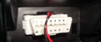
Before connecting, let's look at what the input sockets for the radio in a Toyota Coroll look like. You can see them in the picture below.
There are similar holes on the player itself. In order to independently connect these connectors with wires, you need to know the pinout of the radio - that is, know what each wire is responsible for, and also know the pinout of the input holes in the car itself. We will not talk about the radio, since depending on the manufacturer of the radio, the pinout options also change. For example, SONY has its own pinout, and Pioneer has its own. Typically, the installation and use instructions contain a detailed diagram describing what each wire is for. If you don’t have a manual, you can find these diagrams on the Internet - today they are quite common.
Having talked about the radio, let's talk about the pinout of the sockets on the car itself. The picture below will show a diagram, below which you will find a detailed description of what each contact is needed for. So let's get started.
We see a diagram - it makes no sense to consider it without a description, since each number has its own designation, and incorrectly connecting the wires will simply lead to a short circuit. Therefore, the wires should be connected strictly in accordance with their intended purpose - if it is a permanent plus, then it should be connected to the hole where the permanent plus is located, etc. I hope the principle is clear to you. So let's look at the meaning of each number.
- This number designates the 12V wire that serves as a conductor when the ignition key is turned to the ACC position;
- This number serves as the same 12V current conductor, only in ignition mode;
- The third number indicates the front left speaker with the value “+”;
- The fourth number represents the front right speaker with the value "+";
- This connector remains unused;
- We also do not use this connector; it should remain empty;
- Number seven – antenna power supply;
- Grounding - the use of this connector is mandatory - this is for those who consider it not a first necessity;
- The ninth number is the front left speaker with the value “-”;
- The tenth number is the front right speaker with the value “-”;
- Rear left speaker “+”;
- Rear right speaker “+”;
- Rear left speaker “-”;
- We do not connect;
- We do not connect;
- Rear right speaker "-".
So, when all the values are available, all that remains is to wish you good luck in independently connecting the radio to your favorite car, however, I note that it is much easier to find an adapter and not suffer with the independent connection.
voice
Article rating
Installing a subwoofer in a Toyota Land Cruiser 100
Many Land Cruiser 100 owners are not satisfied with the power of the standard subwoofer, and they install models with better characteristics. Some people find it inconvenient to place a subwoofer in the trunk: it takes up space and can be accidentally damaged by items being transported. This problem is solved by installing an increased power subwoofer in the Land Cruiser in the niches instead of the standard box.
Niche behind the rear wheel arch
The third row of seats can be removed; the subwoofer does not interfere with the rear backrests being tilted as far as possible. The power of a subwoofer depends on the size of the diffuser - the larger it is, the more powerful the system. There is often not enough space for a large diffuser; the problem is solved by using Solobaric speakers from Kicker. Their volume is 40–50% less than typical heads of the same diameter.
You can fit 4 bodies between the wheel arches - the width of the Land Cruiser 100 allows this. The housings are buried as deep as possible into the niche. The curved back wall is glued out of fiberglass, the sides are cut out of plywood.
For high-quality sound of the Toyota Land Cruiser 100 subwoofer, it is important to create an acoustic volume in the niche. For this purpose, bitumen vibration insulation is usually used.
The surfaces are degreased, the material is evenly heated in advance, then glued and rolled out with rollers to remove air. Carpet is placed inside the box and a subwoofer is installed. The holes around it are covered with plywood rings, and the mesh is stretched. To protect the subwoofer, two metal arcs are installed.
In the back door
There is little space in the niche: a lot of space is taken up by lights and rods. The lights are usually left, and the pulls from the handle are moved. Instead of the middle of the door, they are installed under the top edge. They work with an angle grinder, since the metal is profiled, thick, and the structure is reinforced with stiffening ribs. The freed space is soundproofed and a fiberglass subwoofer housing is formed in it.
Total useful volume is 29 liters. It is possible to install flat speakers. For the closed box option, the Pioneer TS-SW1041D is suitable, it can fit two of them.
To switch from the ZY option to a bass reflex one, one Pioneer speaker is replaced with a Kenwood one, and a plywood plug is installed in place of the second one. A 39-centimeter bass reflex port is glued into it. The body is fixed to the metal with self-tapping screws. The sub is covered with a false panel with grills made of 3 mm steel.
Removal and installation
These dismantling instructions are suitable for outdoor type devices.
Dismantling procedure
For a device with a fixed mast, first remove the radio and disconnect the antenna cable from it, carefully removing it from the intermediate clamps.
Next you need:
- Pull the mast out of the base.
- Unscrew the base nut (use pliers to remove the locking rings).
- Pull out the antenna wire and attach part of the string to it.
- Remove dirt and rusty deposits from the mounting area.
This may require the help of a second person. If the drive does not work, the problem is probably in the system relay. To check the drive, return the terminals to the battery, connect the antenna to the radio, and turn the ignition key to Lock.
At this time, one person fixes the mast of the device, the other, inside the car, presses the AM/FM button on the radio. Before checking the antenna on the Land Cruiser Prado 100, the ignition key must be set to ACC. The mast is fully extended, after which it is disconnected from the electric drive of the motor.
If the device jams and does not come out completely, then:
- Press the button on the dashboard repeatedly.
- To fix the device in a raised state, remove the terminal from the battery. The ignition key is left in the start position.
- Remove the right fender liner, finding the antenna drive. It is usually enclosed in transparent polyethylene.
- The fastenings on the wing are unscrewed with pliers (to preserve the paintwork, the hood is covered with a soft cloth).
- Completely pull out the device wire without removing the tied string.
- After removing the wheel arch, remove the mounting bolt and remove the drive motor.
Now all that remains is to disconnect the antenna control wiring cord and pull it out.
Installation
When installing a new antenna, you need to tie its end to the string left in the arched part of the car, carefully pulling it inside the cabin. The electric motor of the mast is returned to its place. The mast itself is secured by turning the wire with its toothed surface facing forward. When the ignition key is set to Lock, the mast runs along the wing, automatically rewinding the cable.
If the key is initially turned to Lock, the cord may not rewind. This happens because the coil does not grip the mechanism. To eliminate the problem you need to:
- Move the cable vigorously from side to side.
- Tighten the nut on the base of the mast.
- If any part of the cable is not completely inserted under the fender, it will finally tighten when you press any button on the car radio.
Instructions for removing the device
Before replacing an installed car radio with a new one, you must first remove the old device.
To remove it, you need to prepare a small set of tools and materials:
- a set of keys for the car radio that it comes with from the factory;
- Phillips and hex screwdrivers;
- stationery knife;
- small box;
- tweezers for removing cladding;
- insulating tape;
- pencil.
Preparation
Before removing the radio from the car, you need to do the following preparatory work:
- Before starting work, you need to turn off the engine and de-energize the car by disconnecting the negative terminal from the battery.
- When removing the plugs from the connectors, do not pull them so as not to break them. All wires from the sockets in the rear should be disconnected as carefully as possible.
- If during dismantling there will be a lot of wires, you should prepare electrical tape and a pencil to then deal with the wiring. Wires must be insulated and labeled.
- Next, you need to prepare the keys for the radio. Each manufacturer uses hidden mounts for their devices. You should understand what fastening material is used and select the appropriate tool. Typically, keys are included with the standard car radio.
- When dismantling, it should be taken into account that some models have slides that help remove the device from its seat.
Car radios differ in design and mounting. There are usually two rectangular and four round mounts.
If there are standard keys, then dismantling should be done with their help.
Basic algorithm of actions
Removing the radio consists of the following steps:
- Before removing the car radio, it is necessary to dismantle the front panel, which protects the internal parts from mechanical damage. It must be removed carefully so as not to damage or scratch the casing.
- The next step is to unscrew the screws that secure the device to the housing. To do this, use a Phillips screwdriver. We put all the bolts and screws in a prepared box so as not to lose them.
- Now the device can be removed from the socket where it is located by pulling it towards you. On some cars, dismantling takes place without problems, but there are models on which it is difficult to remove the device.
- After removing the car radio from its seat, you need to disconnect all connectors. To do this, pull up the blue stoppers, then you need to press the released petal and you can disconnect the power connector. We simply remove the antenna from the socket.
After the device has been removed, the radio is either replaced or repaired if it does not work. If you do not know how to disassemble the device, it is better to entrust the repair to a specialist. If you are confident in your abilities, you need to disassemble the radio, fix the problem and put it back.
Installation of a new product is carried out according to the instructions that came with it. It is important to remember that if you install the radio in your car incorrectly, it will sound bad and may cause a short circuit or even a fire. Therefore, you need to connect the device only according to the instructions.
Scheme with a button
To connect a powerful car radio without the risk of draining the battery, you need to install a button in the power circuit. This results in manual control of the device. To turn on the radio, regardless of the position of the ignition key, you need to press the button. Some car owners believe that there is no need to install additional controls in order to connect the original radio.
The circuit with an additional button does not allow settings to be lost and protects the battery from discharge during the system sleep period. Some Toyota radios have 15 or 16 pins on a large horizontal block, of which 12 can be used.
Therefore, you need to look at the terminal designations of the car chip.
In the auto parts markets, adapters from various audio systems to connectors of a Toyota car of any modification are sold. Using special adapters, you can simply and quickly install the purchased car radio without knowing the pinout.
How to remove the radio without keys?
If standard keys are lost, you need to make homemade ones, focusing on the shape of the slots. To see them, remove the device’s removable panel and plastic frame. Here is a list of available tools with the help of which owners of various cars manage to unlock the latches:
- thin steel strips 6-15 mm wide;
- stationery knives;
- plastic clamps for electrical wiring;
- nails and straight wire - for round holes;
- thin screwdrivers and other similar items that fit the shape of the cracks.
These steel strips can be used instead of keys
Reference. In many radios, the mounting slots are visible from the outside, so there is no need to remove the front panel and plastic frame.
The first step is to remove the front panel of the radio.
To remove the car radio, use the same algorithm:
- Insert first one and then a second strip of thin metal (or a utility knife, thin screwdriver) into the technological opening. Feel each latch unlock.
- If the turntable is supported by 4 clips, insert four instruments.
- Slowly remove the radio from the niche at the same time as the improvised keys.
The strips need to be inserted into the side slots
Advice. When using steel strips to open latches, be sure to wear cloth gloves to avoid cutting your hands on the sharp edges.
The music center is removed along with the strips
Fuses and blocks in the Land Cruiser 100 interior
The fuses in the Toyota Land Cruiser 100, produced from 1998 to 2003, for left-hand drive (LHD) layout are located on the left (when viewed from the passenger compartment). Next to the diagram is:
- fusible links for steering column settings, turn signal relays - No. 1, No. 4;
- key transponder (controlling computer) - No. 5;
- unit that controls door locking and ETC - No. 6, No. 7;
- block that turns on/off the turning headlights - No. 1;
- AHC or relay design designed to control body height - No. 22;
- main airbag unit (located almost in the center of the cabin) - No. 21;
- control block - No. 19;
- deceleration sensor - No. 20;
- control blocks of the dashboard and anti-theft system (located above, in the center) - No. 10, No. 11.
Unlike the specified configuration, in the Toyota Land Cruiser LHD produced in 2003-2007, the fuses for the key autotransponder computer (No. 5) are located on the right, and instead of the distribution block or MTR relay (on the right), a safety block (No. 17) is installed.
Fuse block in the cabin TLC 100 (1998 – 2002)
Kruzak 100 has fuses (fuse blocks) in the cabin that turn off if necessary:
- electric mirrors Land Cruiser 100 (MIRR) - No. 1;
- airbags, seat belt pretensioner (SRS) - No. 2;
- ABS, injection mechanism, other pillows/belts, signal indicating discharge (IGN) - No. 4;
- cigarette lighters, car antenna, audio system (CIGAR) - No. 3;
- rear window heating (DEFOG) - No. 15;
- power windows, lock, sunroof, steering wheel position changes, ABS, seat drive (POWER, ECU-IG) - No. 5, No. 21;
- STOP signals - No. 13;
- lighting (DOME) - No. 6;
- structure for monitoring body position (AHC-IG, AHC-B) - No. 7, No. 18;
- differential lock control circuit (DIFF) - No. 8;
- service warning indicators, gearbox, rear lights, (GAUGE) - No. 9;
- washers, windshield wiper (WIPER) - No. 10;
- device for idling the engine (I/UP) - No. 11;
- rear heater (RR HTR) - No. 20;
- front fog lights (FR FOG) - No. 12;
- rear air conditioner (RR AC) - No. 14;
- anti-theft system, steering wheel adjustment, daytime running lights (ECU-B) - No. 16;
- license plate lighting, side lights, running lights, panel lighting (TAIL) - No. 17;
- diagnostic connector (OBD) - No. 19;
- outlet (PWR OUTLET) - No. 22.
Fuse assemblies LC 100 (2002 – 2007)
The left fuse block of the Land Cruiser 100 includes shutdown control:
- cigarette lighter (CIG) - No. 2;
- air conditioner (A/C) - No. 16;
- gasoline injection circuits (AM1, ECU−IG1) - No. 4, No. 12;
- heated rear window, fuel (DEFOG, FUEL HTR) - No. 5, No. 7;
- additional heater (POWER HTR) - No. 8;
- toxicity reduction (EFI NO.2, ECD NO.2) - No. 10;
- compilation of several devices (GAUGE1) - No. 11;
- sockets (PWR OUTLET) - No. 1;
- navigator (ECU-B1) - No. 13;
- structures for powering the Land Cruiser 100 trailer (BATT CHARGE) - No. 15;
- lights signaling the car to stop (STOP) - No. 17;
- diagnostic connector Land Cruiser 100 (OBD−2) - No. 18;
- idle speed (IDEL UP) - No. 19;
- seat drive left (LH SEAT) - No. 20;
- central locking, power windows (DOOR) - No. 21;
- instrument panel illumination (ACC) - No. 3;
- locking systems (DBL LOCK) - No. 14;
- hatch Land Cruiser 100 (SUN ROOF) - No. 22;
- rear auto glass wiper (RR WIPER) - No. 23;
- body position control (AHC-B, AHC-IG) - No. 6, No. 9.
Land Cruiser 100 (assembly fuses on the right):
- charging for a caravan (BATT CHARGE) - No. 18;
- central lock, power windows (ECU-B2) - No. 1;
- washer (WASHER) - No. 3;
- steering wheel tilt/height adjustment (TIL&TEL) - No. 20;
- interior lighting Land Cruiser 100 (DOME) - No. 5;
- steering (VGRS) - No. 6;
- left window lifters (P/W (FL), P/W (RL)) - No. 7, No. 8;
- windshield wiper (WIPER) - No. 9;
- rear air conditioner (ECU−IG2, RR A/C) - No. 10, No. 21;
- all-wheel drive diagram (DIFF) - No. 2;
- heated seats (SEAT HTR) - No. 11;
- light for automobile R-running (GAUGE2) - No. 12;
- instrument cluster (MET) - No. 13;
- distributed injection system (ING) - No. 14;
- anti-theft (SECURITY) - No. 15;
- rear, front right window lifters (P/W (RR) and P/W (FR)) - No. 16, No. 17;
- audio system (RADIO) - No. 4;
- electric right seat (RH SEAT) - No. 22.
Scheme directly from the battery
Some car owners supply power to the car radio through the cigarette lighter socket. This connection affects the power of the amplifier. At a high volume level, you can see the cigarette lighter light blinking. The best option is to connect the radio device to a battery. Installation must be carried out with high-quality wire, and to protect the circuit, you need to install a fuse in close proximity to the power source.
It should be noted that the pinout of the standard radio assumes the presence of 2 wires supplying +12 V voltage. Most often, the main power is supplied through the yellow conductor, and the red one is intended for turning on and is connected to the ACC (ignition switch). The negative wire has a black braid and is connected to the car body. However, experts recommend connecting it to the negative terminal of the battery. In addition to power circuits, there are wires for connecting speakers.
Installation of the circuit is simple and consists of connecting the power wires to the battery.
But it is good for low power systems. Connecting a more energy-intensive device leads to a complete discharge of the battery within 2-3 days, even in sleep mode.
Features of the Toyota Camry radio pinout
The pinout of the Toyota Camry radio is also not very complicated, but if the motorist is lucky enough to find adapters for the device connector, then he can not fool himself by selecting the right hole and wires of the Toyota Camry radio that match the color.
However, if the owner considers himself a professional and thinks that the pinout of the Toyota Camry radio will suit him, then it’s worth understanding its nuances:
- the wire with a yellow tulip on it can be connected to the rear view camera by connecting the second side to the standard Camry V40 radio;
- connect the wire on which there is a red tulip to the wire that will give a plus when the selector is located in position R;
- connect the red wire to the terminal that activates the KZH to the wiring of the Camry V40 receiver;
- You should also connect the red tulip wire to the positive permanent connector, and connect the black wire to the negative ground.
At the same time, the radio for Toyota Camry can be connected without complex pinouts if a proprietary and high-quality system is purchased. The fact is that it will already have plugs installed that correspond to a specific connector.
Types of radio mounts
To choose a method for removing a car player, you need to understand how it is fixed inside the panel. The following types of fastenings exist:
- on 2 side clamps;
- on 4 latches located on the side and top of the case;
- fastened with self-tapping screws or screws to the brackets.
Example of mounting a standard head unit
Note. The last method of fixation is typical for standard devices that are supplied to the car by the manufacturer.
Latch on mounting frame
The principle of fastening with latches (clamps) is that the body of the radio is enclosed in a metal mounting frame, and is not directly built into the panel niche. This intermediate part, which has special petals with protrusions or grooves (depending on the brand and model of the device), is securely fixed in the niche. The player body is equipped with mating latches that engage when the player is inserted into the socket.
The counterpart of the latch on the body
To unlock the latches and remove the car radio, keys of various shapes are used, supplied by the manufacturer complete with music for the car. They are lost over the years of car operation, since they are used extremely rarely. As a rule, the key is a shaped strip of metal or a handle inserted into 2 pairs of holes located on the front panel of the device.
This is what most car radio removal keys look like
The mountings of standard radios are most often made with bolts, screwed to brackets and hidden under the front plastic panel. Here you cannot do without a minimum set of tools to dismantle this panel and unscrew the mounting screws or bolts.
Handle key for unlocking 4 latches
Reference. All of the listed intricacies with hidden latches and special keys were invented by manufacturers with one goal: to make it as difficult as possible for thieves to steal the car radio when the car is broken into.
Location of key holes
Antenna repair in Toyota Land Cruiser 100
Problem: from the moment of purchasing the Cruiser, the antenna lived its own life: it extended when it wanted, but did not fold when necessary. Today I have some free time to fix this problem, which sooner or later happens to any cruiser or 470.
Progress of work to restore the antenna operation in the Toyota Land Cruiser 100
Removed the right front fender liner
The antenna drive itself is carefully packed by Toyota in a thick plastic bag
Extended the antenna to its full length
When the ignition is turned off, the antenna should essentially fold completely. But it only took me a third of it. And when disassembling, I needed the antenna to be extended as far as possible. I pressed the button, helped a little with my hand, pulled it out, and then, with the ignition key in the ON position, removed the battery terminal. Thus, the antenna did not fold.
I unscrewed the nut on the wing with pliers
I tried everything, but only pliers helped. It is better to put some kind of rag on the side of the hood so as not to damage the paintwork.
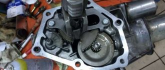
Here's what's inside on the toothed strip
The antenna unit itself is mounted on one bolt
The antenna mechanism itself
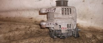
Denso production numbers in the photo
I poured WD-40 into the antenna rod until all the dirt was washed out of it.
After removing the cover, I made a mark on its position on the toothed strip so that when reassembling it, I would put it in the same place.
The other part is also dirty
There was no lubricant like the factory one on hand, so I applied a little lithol where needed. Where the factory lubricant was clean, I didn’t touch it, I tried to preserve it as much as possible.
Toothed belt half cleaned
I cleaned the toothed belt with a rag since there was no toothbrush in the garage. I think it would be much faster with a brush.
Once I cleaned and reassembled everything, it worked great.
Then the antenna started acting up again. I ordered the antenna rod in the hope that with the new teeth it will fold and unfold without problems. What came of it...
I am far from electricians, so for all sorts of such matters I go to specially trained people. The last time they installed speakers, an amplifier, a power steering unit, a rear view camera, and a steering wheel adapter in Autopilot. HELLO guys! and everything seemed to be installed well, although there were some extraneous noises from the GU, they were eliminated, although at first they said that all pioneers have this and this is the norm, to which I replied that a head for almost 30 rubles should not behave like some kind of Elenberg , they found a way out and the noise stopped. I was interested in the question of the antenna, why it doesn’t work from the button, to which I was told that I needed some kind of adapter for the antenna, there was no other way, etc. Well, okay, I thought... I'll come up with something later. So I drove around happy, listening to music from the flash drive and everything was fine until I turned on the radio while driving along the highway - it hissed violently. I bought an antenna amplifier, the guy who sold it swore to my mother that everything would be ok, but it wasn’t ok. Naked China, I thought around and temporarily gave up on this matter. But the button for extending the antenna never gave me any rest... So, it was useful to remove the antenna again. The antenna wire was simply snapped at the antenna unit itself... Once again I want to say hello to the installers! Why you did this is a big mystery to me... I twisted it, insulated it and the radio started playing! No wonder I swore by my mother, I remembered that uncle...
Antenna rod part number in the photo:
By the way, everything is clean inside; after the last cleaning, there was no more dirt. I changed the stem, it doesn't take long, you just need to replace the cap from the old one.
There is not much difference between the old and new teeth...
It's all about these gears:
The teeth on them are worn out. You can't find them on sale. I’ll think about something with them... one of the options that I’m leaning towards is printing on a 3D printer, I’ve already found where to do it, the price is 40 rubles per gram of the finished product.
Toyota Land Cruiser 100 equipment according to Vin
Toyota Land Cruiser All the time I checked my cars by VIN, it’s interesting to know all this! Today I’ll tell you about decoding
Source
Audio system in Toyota Land Cruiser 100
The standard multimedia system of the Land Cruiser 100 includes a head unit, an external amplifier, front and rear speakers, and a subwoofer. The standard 2DIN size radio is installed in the center of the front panel. It has outputs for connecting acoustics and other components.
The Land Cruiser factory installs standard car radios of the following models:
- Pioneer;
- Alpine;
- Sony;
- JVC;
- Phantom.
The sound system is two-way. Front and rear midrange and bass/midrange speakers are located in standard places in the front and rear doors. The factory standard system on Toyota Land Cruiser is DLS RM6 2.
The subwoofer reproduces the lowest frequency sound signals. Structurally, this is a single-way system consisting of a low-frequency speaker and a housing. On the Land Cruiser 100, the rectangular subwoofer is located in the luggage compartment on the left.
Prado car radio pinout
In order for the pinout of the land cruiser 200 2008 radio in TLK to be successful, you need to purchase branded equipment and adapters with the correct connectors.
The pinout of the Toyota Land Cruiser 100 car radio is as follows:
- We connect the yellow tulip to the rear view camera.
- We connect the red tulip to the plus, and the black one to the minus.
If you are not sure that you can handle the pinout of the Land Cruiser 100 radio, entrust this task to a specialist.
Several connection schemes
Pinout of toyota car radio connectors
It is believed that the main mistake when connecting Toyota car radios is pulling the positive wire from the cigarette lighter
This will in no way have any effect, since the power of the head unit will drop several times (this is easy to verify if you pay attention to the flashing backlight while the device is operating at high volume). In addition, connecting Toyota car radios through the cigarette lighter will not eliminate sound distortion, which will begin to appear noticeably earlier
On the other hand, in some cases this option may be considered suitable for implementation. The ideal option for connecting Toyota car radios, as well as all others, is to provide the main power supply from the battery. It is advisable to use high-quality wire (it is in no case recommended to skimp on the cable) and be sure to use a fuse, which must be placed as close to the battery as possible.
Note. Let us note right away that car radios have not one, but two power wires. As a rule, yellow is responsible for the main power, red for control (goes to the lock).
In addition, the pinout of the remaining wires:
- N* – negative wire. They are usually connected to the car body, providing ground. However, it is recommended by experts to connect it to a battery;
- C is the wire that is responsible for the amplifier or active antenna.
In addition, the car radio is also equipped with speaker wires (they go to the rear and front speakers):
- B, C-th – wires for front speakers;
- Z, F – wires for rear speakers.
Note. You also need to know that each pair of acoustic wiring contains additional monotonic and negative wires. The latter is often marked with a black stripe over the main color.
Connection according to diagram 1
Connectors for car radios
- We connect the power wires to each other;
- We connect them to the battery.
The good thing about this scheme is that it is easy to implement. On the other hand, it is only suitable for car radios with low power consumption. If you connect a powerful device according to this scheme, then in just 2-3 days in sleep mode the car radio will completely discharge the battery.
Connection diagram 2
This circuit is suitable for any powerful car radio:
- We connect the power wires to each other;
- We connect them to the battery;
- We install an additional button (it is responsible for turning the device on and off).
This scheme involves manual control of the radio, but the settings will not go wrong and the battery will not run out in a couple of days.
Connection diagram 3
Connector for car radio
Individual scheme, implying the following:
- We connect the main power wire (yellow) to 12 V;
- We connect the additional one (red) to the side lights (via a relay, the winding of which is connected to the ashtray light bulb).
This scheme provides the following advantages:
- The device turns on simultaneously with the “dimensions” automatically;
- The driver will never forget to turn off the side lights and headlights;
- While stopping, you can listen to music without turning on the ignition;
- If you replace conventional small bulbs with LED ones, the electricity consumption will be very low.
There are many more schemes for connecting Toyota car radios, such as connecting via ACC or via an alarm. As a rule, they are not that common and are not suitable for everyone. In particular, connecting via ACC (lock) is inconvenient because the device will not function without a key in the lock.
Connecting the camera according to the pinout
Knowing the pinout of the car radio, you can easily connect the rear view camera with your own hands. Using the example of the popular Toyota Ca-Fi device, we will learn how to do this. The process itself is divided into two parts: the actual installation of the device with the connection and the connection of the rear view camera.
Note. Installing and connecting the monitor is no different from installing the factory head unit. You just need to swap the connectors and that's it.
But connecting the camera can be difficult for some. Here's what you need to know:
- The rear view camera for Toyota Prado is powered by 5V;
- To connect it, you will need a connector from the factory monitor, which remains free after installing the new radio;
- This same connector is 14-pin. But we only need two video signal wires and a reverse signal;
- In addition, you will need to convert the voltage from 12V to 5V.
Note. To convert voltage means to carry out the process using a special converter, which is sold in any store.
The camera connection diagram has its own pinout. This is what she looks like.
Pinout of toyota car radio connectors
The circuit is positioned as if you were looking at it from the side of the wires. The photo in the upper left corner is placed for clarity. So, in order to connect the camera to the Toyota car radio, you must first connect together the reverse signal and the Reverse wire on Ca-Fi. In addition, it will be necessary to install a converter and make a tulip for transmitting video data.
Note. This does not mean that you will have to literally do everything from scratch. You just need to buy Scotchlocks in the same store where you purchased the converter (they will help connect the wires to each other).
The photo below shows how to splice wires using tape.
Scotchlock and wires
Next we do the following:
- We start the car;
- We turn on reverse gear;
- Let's check how everything works (the monitor of the installed radio should show the image from the camera).
Thus, knowing the pinout of Toyota car radios, you can connect using any of the selected schemes. During the work process, it is extremely useful to watch a video review. Step-by-step instructions from other sources will also help. The price of installing a car radio yourself is noticeably different from the cost of specialist services, which is several times higher.
I got lost, I apologize for the long post. As they say: “It was evening, there was nothing to do”...
I continue to put blue parts into the interior. Previously, the following were made: BUO lighting, a blue optitron was installed, Chinese blue covers were purchased from Dishman, the same beef braid for the steering wheel, blue lighting for the legs, the ignition switch, cigarette lighter and ashtray lighting bulbs were replaced with blue LEDs. In general, the result I was striving for was obtained in some form. There was still a question with the radio. One day, while rummaging through the on-board vehicles, I came across an interesting work with a similar SONY radio. Since I could hardly solder such a small thing myself, I decided to contact a radio repair shop. I found the necessary LEDs in the blue LED strip. In the workshop, my brain was floating for 2 weeks, either busy or something else, then they told me that the work was too small, we could not guarantee success in the work. In short, I gave up on it and forgot until a friend offered to sell her my radio. Therefore, I was puzzled by the purchase of a new radio. But what should you buy - a 1din radio with blue backlight or a 2din with a blue menu? The price of the second option is naturally incomparably high. Plus, I’ve been dreaming about an on-board computer for a long time and decided to save 1din for multitronics. There were practically no advertisements for 1din radios on the secondary market; I only looked at one and didn’t buy it (there was a blue glow, not blue). I didn’t see anything decent in the store either, until I came across the JVC KD-R647EED radio
The color from the photo was just right, the price was super, I even left work earlier and went to the store. At the exhibition stand it turned out that the tape recorder was not blue, but blue and did not suit me. Well, I caught a glimpse of the neighboring stands, saw radios that flashed all the colors of the rainbow, and was hooked by the SONY CDX, like the one I have. I asked the manager to turn on the blue color I needed, to which I received a counter offer to wait until someone there found the instructions, read them and did what I asked. So what's the big deal? In short, he asked to open the glass door, in three seconds he found the color choice in the settings and was shocked, there are a lot of colors, you can choose from the standard range + options with tints, or you can create a color yourself using RGB parameters. The price of the mower was more expensive than the previous model, but I decided to take it. Moreover, I have the same one, I am familiar with it. Overall "Wasted"
As it turns out, you need to buy chips
Although, as far as I know, the chips in SONY, JVC and Kenwood radios are identical, which is why I firmly believed that I would get into the car and in a couple of minutes I would listen to the new radio. It wasn’t there, the radio chip doesn’t fit, it’s the same but a little smaller (why bother changing it?). The connection didn't take too long. I disconnected the chip from the old SONY and connected the new chips, looking at the audio system diagram in the primer. I fiddled around with the settings, set it to what I needed and here is the result
I really, really like it =)
PS In addition to the blue parts.
The other day I tried to cover the interior panels with a blue film, I didn’t use a carbon fiber film, but some other film, on some kind of foam base, it turned out like crap, dear mother... The next day I tore everything off and threw it away. There was an idea to find a darker and “carbon-look” film, but I changed my mind. I decided to try looking for marbled panels. Even if there is not a hint of blue, it is simply beautiful.
PPS Has anyone changed the color of the watch? Do they understand at all? In someone’s on-board vehicle I saw a watch that was converted by installing a filter film of the desired color. Please share your experience and knowledge.
I came across an article. Where can I find such a film...
UPD 12/21/13
I disassembled the power window control unit and removed the old LED.
Sometimes car owners are not satisfied with the standard car radio. Replacing it is not difficult at all. An article will help with this, which describes how to remove the radio correctly in order to install a new device.
How the KDSS system works
The essence of the mechanism is simple and ingenious. The front and rear stabilizers, responsible for lateral stability, are connected to each other by means of two hydraulic cylinders. A special fluid circulates through hydraulic cylinders in a closed circuit. The KDSS circuit is equipped with sensors, hydraulic accumulators and valves.
When driving on a flat surface, the valves are closed and the fluid is at rest. At this time, the pistons of the hydraulic cylinders are blocked and rigidly connect the stabilizers to the body, minimizing car roll in high-speed turns. When smooth asphalt is replaced by a broken road, the valves in the hydraulic accumulators open, which allows them to compensate for surges in fluid pressure inside the circuit and reduces shaking inside the car.
Standard pinout
The basic pinout of a standard Toyota radio contains the following cables:
- The gray wire is responsible for providing a positive signal when the key in the ignition control switch is turned to the ACC position.
- To ensure that equipment settings are saved, a cord with a blue-yellow or blue-white insulator is used. A positive signal is given regardless of the position of the key in the lock and the state of the security alarm.
- An additional cable with a green protective layer ensures the operation of the backlight. The cord is connected to the control of side lighting and the brightness control of the lamps.
- To supply negative power, wiring with a brown protective layer is used.
- The block design contains an additional blue cable designed to control the antenna amplifier or an electric drive for extending the antenna pin. Part of the radio has a dark blue output that allows you to control the power of an external amplifier or subwoofer.
- The front speakers are connected through the block in which the power supply cables are located. Each speaker has a negative and positive terminal; grounding the speaker coils to the body is not allowed.
- The rear speakers are located on a separate chip; the design includes a guide pin that prevents erroneous connection. The pads mounted on the car wiring are held on the body of the multimedia device using plastic clips.
The switching scheme depends on the year of manufacture of the machine. For example, the Land Cruser 100 uses a Pioneer GM-9227ZT head unit. The design includes a speaker plug with pins for 2 low-frequency speakers and contacts for supplying positive power. The second plug contains contacts for connecting an antenna, transmitting signals from the on-board computer and controlling ports for external players or drives.
Since 2008, a DVZ-MG8077ZT radio tape recorder with a digital output connector began to be used.
The components are switched using 4 connectors; the design provides a connector for transmitting a signal from a rear view camera. The audio player supports operation with a CD pager; the unit is connected via a separate wiring harness.
Instructions for pinouting radios on Toyotas
When upgrading or reinstalling a standard Toyota radio, vehicle owners who decide to carry out this procedure on their own begin to figure out why the wires are needed and what this or that connector is responsible for.
At the same time, the pinout of the standard Toyota radio can be carried out not only in a service center by professionals, but also with your own hands. At the same time, the pinout of the standard radio for any model, including the Toyota 86120, will work perfectly if the person has minimal experience working with electrical equipment and is not colorblind.
At the same time, the process of pinouting a Toyota Corolla radio or professional pinouting a Toyota Camry radio will not be too different from each other.
The hardest part is pinouting the Toyota 86120 radio, since it is almost impossible to find a process on the Internet that would be clearly described. That is why those who have a Toyota 86120 radio will have to be content with a high-quality photo, but, alas, without an explanation of the pinout process.
Removing the device according to the instructions
The algorithm for removing the radio if you have the keys is outrageously simple. It is worth considering in order to understand how to act if they are lost. The order is as follows:
- Remove the front panel of the player and the decorative plastic frame, prying it up with a flathead screwdriver if necessary.
- Insert the first key into the gap between the housing and the mounting frame, located at the end. You should feel slight resistance as the tool bends the latch.
- Repeat the same action with the second key.
- Grasp the radio with your hands by the protruding parts on the sides of the case and carefully remove it from the niche.
To remove the radio, 2 keys are used
Advice. There is no need to apply much effort; the device should be removed quite easily. At the end, act carefully so as not to pull the wires again and break the contact.
Special keys must be inserted into the side openings
When the radio is equipped with four latches, access to them is through 2 pairs of round holes. You need to insert 2 U-shaped keys into them and pull them out by the body, as described above.
The music center can be easily removed using keys
Removal and installation
These dismantling instructions are suitable for outdoor type devices.
Dismantling procedure
For a device with a fixed mast, first remove the radio and disconnect the antenna cable from it, carefully removing it from the intermediate clamps.
- Pull the mast out of the base.
- Unscrew the base nut (use pliers to remove the locking rings).
- Pull out the antenna wire and attach part of the string to it.
- Remove dirt and rusty deposits from the mounting area.
This may require the help of a second person. If the drive does not work, the problem is probably in the system relay. To check the drive, return the terminals to the battery, connect the antenna to the radio, and turn the ignition key to Lock.
At this time, one person fixes the mast of the device, the other, inside the car, presses the AM/FM button on the radio. Before checking the antenna on the Land Cruiser Prado 100, the ignition key must be set to ACC. The mast is fully extended, after which it is disconnected from the electric drive of the motor.
If the device jams and does not come out completely, then:
- Press the button on the dashboard repeatedly.
- To fix the device in a raised state, remove the terminal from the battery. The ignition key is left in the start position.
- Remove the right fender liner, finding the antenna drive. It is usually enclosed in transparent polyethylene.
- The fastenings on the wing are unscrewed with pliers (to preserve the paintwork, the hood is covered with a soft cloth).
- Completely pull out the device wire without removing the tied string.
- After removing the wheel arch, remove the mounting bolt and remove the drive motor.
Now all that remains is to disconnect the antenna control wiring cord and pull it out.
Installation
When installing a new antenna, you need to tie its end to the string left in the arched part of the car, carefully pulling it inside the cabin. The electric motor of the mast is returned to its place. The mast itself is secured by turning the wire with its toothed surface facing forward. When the ignition key is set to Lock, the mast runs along the wing, automatically rewinding the cable.
If the key is initially turned to Lock, the cord may not rewind. This happens because the coil does not grip the mechanism. To eliminate the problem you need to:
- Move the cable vigorously from side to side.
- Tighten the nut on the base of the mast.
- If any part of the cable is not completely inserted under the fender, it will finally tighten when you press any button on the car radio.
Video “Procedure for removing a car radio”
- Clarion car radios made in the Land of the Rising Sun: what to expect?
- Repair and replacement of a standard car radio: a cheat sheet for the car owner
- Connecting the radio via the computer's power supply
Many motorists face the problem of removing the radio in their car. Some people cannot remove the standard device installed at the factory, others inherited the music along with the car, and others simply lost special keys. There are also plenty of reasons for dismantling - from repairing wiring to buying a new stereo system. Hence the demand for information arose on how and with what help you can carefully remove the car radio without damaging the plastic of the front panel. And although the operation is primitively simple and can be easily performed with improvised means, there are pitfalls in it that you need to be aware of.