TEST SEQUENCE
- Perform a test that simulates the fault condition by selecting Active Diagnostic Mode (Signal Test Mode) on the handheld scan tool (Click here).
- With Active Diagnostic Mode (Signal Test Mode) selected, perform a test that simulates fault conditions by wiggling each SRS connector or driving on suburban or rough roads (Click here).
Disconnect the cable from the negative (-) battery terminal and wait at least 90 seconds.
Check that the connectors are correctly connected to the SRS central control unit assembly.
OK: The connector is connected correctly.
HINT: If the connector is not securely connected, reconnect it and proceed to the next test.
Disconnect the connector from the passenger's front airbag.
Check that the instrument panel wiring harness connector (passenger's front airbag side) is not damaged.
OK: The lock button is not released and the lock latch is not deformed or damaged.
Connect SST (2.1 ohm resistance) to connector E (orange connector).
WARNING: Never connect the scan tool to the passenger front airbag (passenger side squib) for measurement as this may result in serious injury due to airbag deployment.
- When connecting, do not force the SST into the connector pins.
- Insert SST straight into the connector pins.
Connect the cable to the negative (-) terminal of the battery and wait at least 2 seconds.
Turn the ignition ON (IG) and wait at least 60 seconds.
Clear stored DTCs (Click here).
Turn the ignition ON (IG) and wait at least 60 seconds.
OK: DTC B1805, B1806, B1807, B1808 or 52 is not output.
HINT: Codes other than DTCs B1805, B1806, B1807, B1808 and 52 may be output at this time and are not associated with this test.
Result:
| Result | Next step |
| NG | A |
| OK (for sedan models) | B |
| OK (for hatchback models) | C |
Disconnect the cable from the negative (-) battery terminal and wait at least 90 seconds.
Disconnect SST from connector E.
Check that the connectors are correctly connected to the SRS central control unit assembly.
OK: The connector is connected correctly.
HINT: If the connector is not securely connected, reconnect it and proceed to the next test.
Disconnect the connectors from the SRS central control unit.
Make sure the connector pins are not damaged.
OK: The contacts are not deformed or damaged.
Check that the short spring of the instrument panel harness connector with anti-trigger mechanism is not deformed or damaged.
OK: The short spring is not deformed or damaged.
Connect the cable to the negative (-) terminal of the battery and wait at least 2 seconds.
Turn on the ignition (IG).
Measure the voltage according to the values given in the table.
Rated voltage:
| Contacts for connecting a diagnostic tool | Switch position | Specified conditions |
| U1-2 (P+) - mass | Ignition on (IG) | Less than 1 V |
| U1-1 (P-) - mass | Ignition on (IG) | Less than 1 V |
Disconnect the cable from the negative (-) battery terminal and wait at least 90 seconds.
Measure the resistance according to the values given in the table below.
Nominal resistance:
| Contacts for connecting a diagnostic tool | Switch position | Specified conditions |
| U1-2 (P+) — U1-1 (P-) | Always | Less than 1 ohm |
Measure the resistance according to the values given in the table below.
Nominal resistance:
| Contacts for connecting a diagnostic tool | Switch position | Specified conditions |
| U1-2 (P+) - mass | Always | 1 MΩ or more |
| U1-1 (P-) - mass | Always | 1 MΩ or more |
Open the anti-trigger mechanism built into connector B (Click here).
Measure the resistance according to the values given in the table below.
Nominal resistance:
| Contacts for connecting a diagnostic tool | Switch position | Specified conditions |
| U1-2 (P+) — U1-1 (P-) | Always | 1 MΩ or more |
Return the anti-trigger mechanism of connector B to its original state.
Connect the connectors to the passenger's front airbag and the SRS central control unit.
Connect the cable to the negative (-) terminal of the battery and wait at least 2 seconds.
Turn the ignition ON (IG) and wait at least 60 seconds.
Clear stored DTCs (Click here).
Turn the ignition ON (IG) and wait at least 60 seconds.
OK: DTC B1805, B1806, B1807, B1808 or 52 is not output.
HINT: Codes other than DTCs B1805, B1806, B1807, B1808 and 52 may be output at this time and are not associated with this test.
Result:
| Result | Next step |
| OK | A |
| NG (for sedan models) | B |
| NG (for hatchback models) | C |
Return the anti-trigger mechanism of connector B to its original state.
Make sure the connectors connecting the instrument panel wiring harness to the instrument panel are securely connected.
OK: The connectors are connected properly.
HINT: If the connectors are not securely connected, reconnect them and proceed to the next test.
Disconnect the connectors connecting the instrument panel wiring harness to the instrument panel.
Make sure the connector pins are not damaged.
OK: The contacts are not deformed or damaged.
Check that the short spring of the instrument panel harness connector with anti-trigger mechanism is not deformed or damaged.
OK: The short spring is not deformed or damaged.
Connect the cable to the negative (-) terminal of the battery and wait at least 2 seconds.
Turn on the ignition (IG).
Measure the voltage according to the values given in the table.
Rated voltage:
| Contacts for connecting a diagnostic tool | Switch position | Specified conditions |
| EU1-1 (P+) - mass | Ignition on (IG) | Less than 1 V |
| EU1-2 (P-) - mass | Ignition on (IG) | Less than 1 V |
Disconnect the cable from the negative (-) battery terminal and wait at least 90 seconds.
Measure the resistance according to the values given in the table below.
Nominal resistance:
| Contacts for connecting a diagnostic tool | Switch position | Specified conditions |
| EU1-1 (P+) – EU1-2 (P-) | Always | Less than 1 ohm |
Measure the resistance according to the values given in the table below.
Nominal resistance:
| Contacts for connecting a diagnostic tool | Switch position | Specified conditions |
| EU1-1 (P+) - mass | Always | 1 MΩ or more |
| EU1-2 (P-) - mass | Always | 1 MΩ or more |
Open the anti-trigger mechanism built into connector B (Click here).
Measure the resistance according to the values given in the table below.
Nominal resistance:
| Contacts for connecting a diagnostic tool | Switch position | Specified conditions |
| EU1-1 (P+) – EU1-2 (P-) | Always | 1 MΩ or more |
Connect the cable to the negative (-) terminal of the battery and wait at least 2 seconds.
Turn on the ignition (IG).
Measure the voltage according to the values given in the table.
Rated voltage:
| Contacts for connecting a diagnostic tool | Switch position | Specified conditions |
| U1-2 (P+) - mass | Ignition on (IG) | Less than 1 V |
| U1-1 (P-) - mass | Ignition on (IG) | Less than 1 V |
Disconnect the cable from the negative (-) battery terminal and wait at least 90 seconds.
Measure the resistance according to the values given in the table below.
Nominal resistance:
| Contacts for connecting a diagnostic tool | Switch position | Specified conditions |
| U1-2 (P+) — U1-1 (P-) | Always | Less than 1 ohm |
Measure the resistance according to the values given in the table below.
Nominal resistance:
| Contacts for connecting a diagnostic tool | Switch position | Specified conditions |
| U1-2 (P+) - mass | Always | 1 MΩ or more |
| U1-1 (P-) - mass | Always | 1 MΩ or more |
Open the anti-trigger mechanism built into connector D (Click here).
Measure the resistance according to the values given in the table below.
All errors TOYOTA 4RUNNER, ALLEX, ALLION, ALPHARD, ALTEZZA, ARISTO, AURION, AURIS, AVALON, AVENSIS, AYGO, BB, BELTA, BLADE, BREVIS, CALDINA, CAMI, CAMRY, CELICA, CELSIOR, CENTURY, COROLLA, ECHO, ESTIMA , FJ CRUISER, FORTUNER, FUNCARGO, GT86, HARRIER, HIACE, HIGHLANDER, HILUX, INNOVA, IPSUM, iQ, ISIS, IST, KLUGER HYBRID, KLUGER V, LAND CRUISER, LAND CRUISER PRADO, MARK, MARK X, MATRIX, MR 2 , NADIA, NOAH, OPA, PASSO, PLATZ, PREMIO, PREVIA, PRIUS, PROBOX, PROGRES, RACTIS, RAUM, RAV4, RUSH, SAI, SEQUOIA, SIENNA, SIENTA, SOLARA, TACOMA, TUNDRA, URBAN CRUISER, VANGUARD, VELLFIRE, VENZA, VERSO, VITZ, VOLTZ, VOXY, WILL CYPHA, WILL VS, WINDOM, WISH, YARIS.
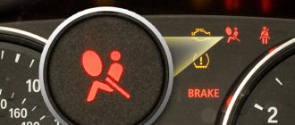
AIR BAG SYSTEM, Diagnostic DTC:B1805, B1806, B1807, B1808
DESCRIPTION
The front passenger airbag squib circuit includes the SRS central control unit and the passenger front airbag.
The SRS central control unit uses this circuit to deploy the airbag when deployment conditions are met.
These DTCs are set when a malfunction is detected in the front passenger airbag squib circuit.
| DTC No. | Malfunction | DTC Detection Condition | Faulty area | Warning indication | Diagnostic mode / test mode |
| B1805 | Short circuit in squib P circuit |
|
| Lights up | Refers to test mode |
| B1806 | Open circuit of squib P |
|
| Lights up | Refers to test mode |
| B1807 | Short circuit in squib P circuit (to ground) |
|
| Lights up | Refers to test mode |
| B1808 | Short circuit in squib P circuit (to +B) |
|
| Lights up | Refers to test mode |
Error table
The main codes unique to the model can be found in the table below:
| Code | What does it mean |
| 13 | Abnormal motor speed |
| 19 | The accelerator pedal is in the wrong position |
| 22 | Coolant temperature sensor is faulty |
| 24 | Intake air temperature sensor does not work well |
| 35 | Boost pressure has dropped |
| 39 | Fuel sensors are not working correctly |
| 42 | Speed sensor is faulty |
| 96 | Incorrect EGR valve position |
| 12 | Crankshaft position is incorrect |
| 14 | The injection timing valve is faulty |
| 15 | Broken throttle servo |
| 17 | ECU signal problems |
| 18 | The bypass solenoid valve is not working properly |
| 32 | Correction resistors have failed |
Deciphering Avensis fault codes
Unlike the first generation T22, in the second release of T25 from 2004-2005, two-digit blink codes appeared that can be read during self-diagnosis and checked with the table above or in the user manual. The self-diagnosis procedure looks like this:
- find the DLC1 connector under the hood of the car;
- take a thin metal jumper (for example, wire);
- using the diagram on the protective cover of the connector box, find contacts TE1 and E1;
- install a jumper to connect the contacts;
- turn on the ignition with the heating/air conditioning turned off;
- Wait for the Check Engine light to flash.
The number of flashes indicates the code. The gap between two ciphers exceeds 2 seconds. Between tens and ones - one and a half. An interval smaller than this indicates units.
Error C1201: Toyota Avensis
Often found in cars produced in 2006-2008. Indicates poor throttle operation. The repair consists of cleaning the damper and intake manifold.
Avensis 2: error C1203
Occurs when the automatic transmission control module breaks down. In most cases it needs to be replaced.
Error C1246
Indicates a malfunction of the pressure sensor in the master cylinder of the brake system. Usually associated with contact problems or breakdown of the ABS system.
B2799 - Avensis malfunction
This error first began to appear on the 1998 modification. It is associated with a broken ignition coil, the replacement of which is important.
Faults 21 and 24
Their appearance indicates problems with the fuel temperature sensor. The device needs to be replaced.
Error 23
In Toyotas 2007 and younger, it indicates problems with the intake air temperature sensor. Most often it needs to be replaced.
Toyota Avensis: error P0037
Occurs when moisture enters the air sensor connector in the lambda probe heater circuit. You can't do without replacement. It happens that the cause of the error is a banal short circuit.
Code P0012
The appearance indicates the need to replace the VVTI coupling.
P0051 - code
Appears when moisture gets into the heated oxygen sensor, causing it to overheat. In many cases, it is enough to get rid of the moisture and the problem will disappear.
Code P0200
This indicates a malfunction in the engine injector wiring, which should be checked for integrity. Sometimes a breakdown of the power unit control unit is to blame.
Malfunction P0500
It speaks of poor contact in the ABS unit.
Code P0556: Avensis
Indicates a problem in the brake booster circuit. Usually, to eliminate it, you need to connect it under the intake manifold.
P1047 - code Avensis
Indicates an open circuit in the VVTI controller. In some cases, the problem lies in the filling of low-quality oil.
Code P1049
Indicates a malfunction in the internal circuit of the Valvematic control unit. In most cases, the latter will need to be replaced.
TRC VSC error
Most often the reason lies in poor contact. If the TRC OFF and VSC lamps light up together, then the sensors on the drive wheels are faulty. In winter, this may indicate a simple failure of the on-board computer due to frost. If the check light is also on, then the problem should be looked for in the engine.
PS Error
Indicates problems with the power supply to the power steering. Contact verification required.
Climate control errors
If a car owner encounters a set of codes 21, 23, 24, 41, 46, then with the maximum probability he has encountered a similar breakdown. Check the contacts and integrity of the wiring, the functionality of system sensors that are prone to failure.
ABS faults: Avensis 2
The appearance of errors 11, 12, 13 and 14 signals similar breakdowns. Contacts deserve special attention. You need to check them carefully before you start checking the block itself.
Error B1806 fault code decoding
Not only do OBD2 errors in the operation of the engine or other electronic systems of the car do not always directly indicate a non-functioning element, but in different brands and models of cars the same error can occur as a result of the malfunction of completely different elements of the electronic system.
We hope, with your help, to form a cause-and-effect relationship for the occurrence of a particular OBD2 error in a specific car (make and model). As experience has shown, if we consider a specific make and model of a car, then in the vast majority of cases the cause of the error is the same.
If the error indicates incorrect parameters (high or low values) of any of the sensors or analyzers, then most likely this element is working, and the problem must be looked for, so to speak, “upstream”, in the elements whose operation is analyzed by the sensor or probe.
If the error indicates a constantly open or closed valve, then you need to approach the issue wisely, and not thoughtlessly change this element. There may be several reasons: the valve is clogged, the valve is jammed, the valve receives an incorrect signal from other faulty components.
Errors in the operation of the OBD2 engine and other vehicle systems do not always directly indicate a non-functioning element. The error itself is indirect evidence of a malfunction in the system, in a sense a hint, and only in rare cases a direct indication of a faulty element, sensor or part. Errors (error codes) received from a device or scanner require correct interpretation of the information, so as not to waste time and money on replacing working elements of the car. The problem often lies much deeper than it seems at first glance. This is due to the fact that information messages contain, as mentioned above, indirect information about the disruption of the system.
Here are a couple of general examples. If the error indicates incorrect parameters (high or low values) of any of the sensors or analyzers, then most likely this element is working, since it analyzes (produces certain parameters or values), and the problem must be looked for “upstream”, so to speak, in elements whose operation is analyzed by a sensor or probe.
If the error indicates a constantly open or closed valve, then you need to approach the issue wisely, and not thoughtlessly change this element. There may be several reasons: the valve is clogged, the valve is jammed, the valve receives an incorrect signal from other faulty components.
Another point that I would like to note is the specifics of a particular brand and model. Therefore, if you recognize an error in the operation of the engine or other system of your car, do not rush to make hasty decisions, but approach the issue comprehensively.
Reset Toyota Avensis errors
To clear a fault, for example an Airbag, you need to disconnect the terminals from the battery for 15 minutes. After this, the error is erased from the memory of the control unit, unless it is repeated. If it appears, it will disappear only after the cause of the code is eliminated.
Specialization: Graduated from the State Automobile University, worked for 20 years at GAZ-56, now I drive a Zhiguli.
I had to create a topic because... No one apparently went to the old one where they wrote..
Guys, has anyone figured out 1806? I had such a situation, I immediately got 2 errors 1232 (pressure regulator) and 1806 (brakes). The car clearly stalled, and after resetting the errors it drove on as if nothing had happened. I read a lot about the injection pump, I thought I was in for money, but no, the injection pump showed 6.95 pressure. But 1806 still torments me. And there is very little information on this matter. I drive fast and brake sharply, and recently this nonsense appeared: when braking and turning (mostly for some reason to the right), the car stalls... and then this bullshit 1806 is read. Today I drove calmly, up to 70 km/h... and braked smoothly, the car never jerked, did not stall, and the speed did not drop. Well, you don’t always drive like this! :).. blackcedric wrote - “This error comes on when your idle speed becomes low, i.e. less than 700. Look what causes the speed to drop to this level.” Actually a question. Where to look then. There are no more errors. Please advise if anyone knows...
I decided to start small... change the spark plugs, since they cost a hundred rubles. But what are my relatives like? Tell. Otherwise I read that it even depends on the month of release which ones to install. And I can’t figure out the month either, because... cedron constructor.
Z.Y. Off topic: how to make a signature.. so that it appears in every message?
Error 1806
Address: Khabarovsk Posts 178
Error P1806 in the original translation Negative signal brake system pressure sensor on the scanner is identified as break vacuum sensor
The error occurs under one of the conditions: 1 - open or short circuit in the vacuum sensor circuit 2 - deviation of the vacuum sensor signal value from the tolerance specified in the engine control unit
This sensor is installed in the vacuum brake booster, indicated in the diagram. The connector has the following pinout
The extreme contacts are power: 0 (ground) and + 5 V. If there is no power, then there are two options - either the wiring is broken or the ECU is faulty (but since not only this sensor, but other elements are powered by five volts, this will immediately occur noticeable).
The functionality of the sensor itself can be checked with a voltmeter or oscilloscope using the central contact (signal wire), but it is better to use a scanner, parameter VACUUM SEN 1. With the engine running, the voltage should be from 1.4 V to 2 V
With the engine turned off and the brake pedal released, the brakes should remain at approximately the same level as before stopping the engine.
When you press the brake pedal, the voltage at the sensor should increase.
The functionality of the sensor can also be checked using a vacuum pump and a vacuum gauge, connected to a vacuum amplifier.
A working sensor should have the following parameters:
At atmospheric pressure - 1 V At vacuum? 13 kPa?? 100 mmHg? - 1.5 V When discharged? 27 kPa?? 200 mmHg? — 2 V When discharged? 40 kPa?? 300 mmHg? — 2.6 V
This sensor is used in the operating algorithm of the direct fuel injection system into the cylinders and was installed on cars with VQ25DD and VQ30DD engines; the VQ30DET and RB25DET do not have these sensors.
Table: SRS fault codes
Table: SRS system fault codes.
| Code | SAE Code | Diagnosed fault | Fault location |
| 11 | B0102 | Short to ground in the driver airbag igniter circuit | Driver's airbag igniter Spiral wire SRS control unit Wire harnesses |
| 12 | B0103 | Short to power in the driver airbag igniter circuit | Driver's airbag igniter Spiral wire SRS control unit Wire harnesses |
| 13 | B0100 | Short circuit in the driver airbag igniter circuit | Driver's airbag igniter Spiral wire SRS control unit Wire harnesses |
| 14 | B0101 | Open circuit in the driver airbag igniter circuit | Driver's airbag igniter Spiral wire SRS control unit Wire harnesses |
| 53 | B0105 | Short circuit in the passenger airbag igniter circuit | Passenger airbag igniter SRS control unit Wiring harnesses |
| 54 | B0106 | Open circuit in the passenger airbag igniter circuit | Passenger airbag igniter SRS control unit Wiring harnesses |
| 51 | B0107 | Short to ground in the passenger airbag igniter circuit | Passenger airbag igniter SRS control unit, wiring harnesses |
| 52 | B0108 | Short to power in the passenger airbag igniter circuit | Passenger airbag igniter SRS control unit, wiring harnesses |
| 43 | B0110 | Short circuit in the right side airbag igniter circuit | Right side airbag igniter Central SRS sensor Wiring harnesses |
| 44 | B0111 | Open circuit in the right side airbag igniter circuit | Right side airbag igniter Central SRS sensor Wiring harnesses |
| 41 | B0112 | Short to ground in the right side airbag igniter circuit | Right side airbag igniter Central SRS sensor Wiring harnesses |
| 42 | B0113 | Short to power in the right side airbag igniter circuit | Right side airbag igniter Central SRS sensor Wiring harnesses |
| 47 | B0115 | Short circuit in the left side airbag igniter circuit | Left side airbag igniter Central SRS sensor Wiring harnesses |
| 48 | B0116 | Open circuit in the left side airbag igniter circuit | Left side airbag igniter Central SRS sensor Wiring harnesses |
| 45 | B0117 | Short to ground in the left side airbag igniter circuit | Left side airbag igniter Central SRS sensor Wiring harnesses |
| 46 | B0118 | Short to power in the left side airbag igniter circuit | Left side airbag igniter Central SRS sensor Wiring harnesses |
| 15 | B1156 | Short to power supply of the right front SRS sensor | Right front SRS sensor, wiring harnesses |
| 15 | B1157 | Short to ground right front SRS sensor | Right front SRS sensor, wiring harnesses |
| 16 | B1158 | Short to power left front SRS sensor | Left front SRS sensor, wiring harnesses |
| 16 | B1159 | Short to ground left front SRS sensor | Left front SRS sensor, wiring harnesses |
| 63 | B0130 | Short circuit in the right seat belt pretensioner igniter circuit | Right seat belt pretensioner igniter SRS control unit, wiring harnesses |
| 64 | B0131 | Open circuit in the right seat belt pretensioner igniter circuit | Right seat belt pretensioner igniter SRS control unit, wiring harnesses |
| 61 | B0132 | Short to ground in the right safety pretensioner igniter circuit | Right seat belt pretensioner igniter SRS control unit, wiring harnesses |
| 62 | B0133 | Short to power in the right seat belt pretensioner igniter circuit | Right seat belt pretensioner igniter SRS control unit, wiring harnesses |
| 73 | B0135 | Short circuit in the left seat belt pretensioner igniter circuit | Left seat belt pretensioner igniter SRS control unit, wiring harnesses |
| 74 | B0136 | Open circuit in the left seat belt pretensioner igniter circuit | Left seat belt pretensioner igniter SRS control unit, wiring harnesses |
| 71 | B0137 | Short to ground in the left seat belt pretensioner igniter circuit | Pretensioner electric igniter left seat belt SRS control unit, wiring harnesses |
| 72 | B0138 | Short to power in the left seat belt pretensioner igniter circuit | Pretensioner electric igniter left seat belt SRS control unit, wiring harnesses |
| 31 | B1100 | SRS control unit malfunction | SRS control unit |
| 32 | B1140 | Right side SRS sensor malfunction | Right Side SRS Wiring Harness |
| 33 | B1141 | Left side SRS sensor malfunction | Left Side SRS Wiring Harness |
| 24 | B1135 | Malfunction of SRS control unit connectors | SRS control unit connectors SRS control unit |
Note:
– If the indicator remains lit after the system normal status code is displayed, this indicates a loss of supply voltage.
– If there are two or more fault codes, they are displayed starting with the lowest number,
– If a code not listed in the table is displayed, the SRS control unit is faulty.
Table with errors
Full description of error codes for Toyota cars:
General faults
The following components are subject to diagnosis:
- all sensors installed on wheels;
- anti-slip system control unit;
- wires from the ABS control module to the controllers and control unit;
- contacts on the regulators.
Transmission faults
- malfunction of the speed shift sensor;
- gear drive failure;
- damage to the cable or one of the contacts on it;
- software malfunction of the control unit or use of an old version of software (software);
- lack of communication between the engine and gearbox control modules.
Possible causes of the malfunction:
- selection mechanism stroke sensor;
- incorrect operation of the selector drive unit and speed switch assembly (system electric motor);
- automatic transmission module malfunction;
- damage or wear to the shift joint or fork rod.
- malfunction of the drive device for selecting and switching speeds in the assembly;
- short circuit in the transmission electric motor line;
- problems in the operation of the TCM module.
More details on what to check:
- Screen filters for the solenoid valve of the variable valve timing drive. These elements can be clogged or torn, and sometimes they are not installed correctly.
- Leakage of motor fluid at the seating surfaces of the gas distribution valve drive unit seals.
- Interruption of the supply of engine fluid to the solenoid valve of the drive mechanism.
- Integrity of the timing belt for wear.
Possible causes of the problem:
- incorrect compression in the engine cylinders;
- air leak;
- damage to the cylinder head gasket or head;
- faulty or clogged mass air flow sensor;
- failure of the lambda probe or damage to one of the contacts on the devices;
- fuel filter clogged;
- injector malfunction.
- failure or incorrect functioning of the electric pneumatic valve for controlling the turbocharger;
- break or short circuit on the vacuum control line;
- malfunction of the turbocharger device;
- breakdown of the recirculation system valve;
- damage to vacuum pipes or leakage;
- malfunction of the power unit control unit.
- malfunction of the fuel filter device;
- leakage or loosening of the fuel line clamps (you need to check the integrity of the nut for tightening the fuel pump cover and housing);
- breakdown of the fuel pump device.
Possible causes of the malfunction:
- battery discharge or damage;
- malfunction of the ignition switch or Start/Stop system;
- regular use of low-quality fuel;
- problems with the immobilizer;
- malfunction of the anti-theft system;
- critical engine failure;
- clogged one of the filters that affects startup;
- faulty injectors or oxygen sensors.
Sensor malfunctions
To resolve the issue, it is recommended to do the following:
- Check the integrity of the connectors on the block connecting the sensor to the dashboard. Perhaps the contact has come loose and needs to be reconnected.
- Diagnose the integrity of the cable through which the sensor is connected to the instrument cluster.
- Check the quality of the connection between the controller and the transmission unit.
- Carry out diagnostics of contacts for short circuits.
- malfunction of the boost pressure controller, sensor parameters are not within the range of normalized values;
- problems in the functioning of the turbocharger control drive unit.
- damage to the sensor power wiring or the bulbs installed in the brake lights;
- failure of the relay or safety device of the optical elements;
- damage to the fuse socket or contacts;
- malfunction of the sensor installed on the brake pedal;
- problems with the control unit.
- malfunction of the left or right front engine speed controller;
- damage to the wiring supplying the regulator;
- malfunction of the rotor speed mechanism;
- errors made when installing the sensor;
- Malfunction of the brake actuator control module assembly (ABS).
Electrical and electronic faults
Possible causes of the malfunction:
- the heating element has failed;
- the lambda probe fuse is blown;
- the wiring supplying the sensor is damaged, or a short circuit has occurred in the electrical circuit;
- the contact on the controller power supply has oxidized;
- The ECM motor control unit has failed or is not working correctly.
- stopping the engine when idling;
- difficulty starting the engine;
- “triple” of the power unit when driving uphill;
- RPM surges.
Possible causes of the malfunction:
- battery discharge;
- damage to the battery, which led to leakage of electrolyte and its inoperability;
- oxidation of the battery terminals or damage to the clamps;
- generator device malfunction;
- failure of the regulator relay;
- Damage or breakage of the drive belt.
Possible causes of the problem:
- failure of the clutch release actuator device;
- the smoothness of the fork or release bearing is impaired;
- failure of the clutch basket;
- use of non-original spare parts to repair the system;
- errors made when installing parts;
- using a control unit with outdated software.
- line damage or short circuit on the reverse light switch wire;
- failure of the switching mechanism travel controller;
- breakdown of the travel sensor of the selection mechanism;
- a malfunction of the TCM module or a software failure in its operation;
- Reverse light switch is broken.
- the control unit has not calibrated the zero position of the deceleration controller;
- the vehicle position was not stabilized during calibration;
- the SRS control module is faulty or operates intermittently;
- the control unit has failed or is not functioning correctly.
- broken or damaged line of the speed shift solenoid valve SR;
- SLU is shorted or disconnected.
damage to the wires on the instrument cluster or disconnection of contacts;
malfunction of the main wiring harness in the engine compartment;
failure of the left front anti-skid sensor;
Possible causes of the problem:
damage or wear of the harness with electrical circuits connected to the instrument cluster;
malfunction of the twisted wire assembly;
failure or disconnection of the contact from the horn button;
- the anti-skid system control module detects an impulse of a break or damage to the power line of the rear left squib;
- breakdown of the airbag knock sensor;
- failure of the control module or software failure of the SRS device.
- short circuit in the power supply wiring of the driver's knee airbag knock sensor;
- failure of the device's squib;
- breakdown or software malfunction in the operation of the SRS control module.
- Communication error between the engine control module and the ID code block. A detailed diagnosis of the wiring harness is required.
- Communication line failure. It is recommended to diagnose the ECM module.
- Identification element differences detected during the exchange of information between the identifier module and the ECM. It is necessary to check the operation of the modules.
To diagnose, you need to do the following:
- Check the battery. The cause of the problem may be its discharge, which causes the generator to work in increased mode, which leads to an increase in voltage. You need to make sure that there is no damage to the battery case, as well as the integrity of the contact clamps.
- Perform diagnostics on the generator drive belt. If the product is worn out, it must be replaced.
- Check the operation of the generator device. The cause of the problem may be a faulty regulator relay.
To find the cause, perform the following steps:
- the sensor itself is checked - the contact may have come off the device;
- diagnostics of the electrical circuit connected to the sensor is performed;
- The parking radar control unit is diagnosed.
Two-digit Type 9 codes
Possible causes of the malfunction:
- damage to the pins on the connection block;
- cable break or wear of the insulating layer;
- malfunction of the EFI unit itself;
- software problem;
- Battery malfunction.
- candles;
- coils;
- high-voltage wires;
- distributor.
Fault codes are considered for the following Toyota models:
- 4Runner
- Avensis T25 (Avensis T25);
- Avalon (Avalon);
- Auris (Auris);
- Aristo (Aristo);
- Brevis (Brevis);
- Caldina (Kaldina);
- Carina (Karina);
- Cami (Kami);
- Camry V40 (Camry);
- Chaser (Chaser);
- Corolla MMT, Ceres, SV40 (Corolla);
- Corona Premio (Crown Premio);
- Crown 1G FE (Crown);
- Estima (Estima);
- Fielder;
- Isis (Isis);
- Ipsum (Ipsum);
- Gracia (Grace);
- Granvia (Granvia);
- Highlander (Highlander);
- Hilux (Hilux);
- Land Cruiser 200 (Land Cruiser);
- Majesta (Majesta);
- Mark, Mark2 (Mark);
- Nadia (Nadia);
- Noax (Noah);
- Passo (Passo);
- Platz
- Prado (Prado);
- Previa (Previa);
- Prius (Prius);
- Rav4 (Rav 4);
- Soarer (Sorer);
- Surf
- Town;
- Verso (Verso);
- Vista (Vista);
- Vitz (Vitz);
- Wish (Wish);
- Yaris (Yaris);
- Windom (Windom);
From english:
Decoding the error B1806 from Dodge: Wireless Communication Antenna Circuit (Bluetooth)
Make:
Dodge
Code:
B1806
Definition:
Wireless Communication Antenna Circuit (Bluetooth)
Description:
Ignition ON.Battery voltage must be between 9-16 volts.The CIM tests the antenna once every second.
Cause:
The CIM detects a short to ground or an open/high resistance in the Bluetooth ® antenna.
How to diagnose the error?
The self-diagnosis process for Toyota vehicles can only be performed using connectors DLC1 and DLC2.
The test block is made in the form of a small plastic module equipped with a lid. Depending on the car model, the location of the connector may vary, but usually it is located in the engine compartment on the left side. On the block cover there is the inscription “Diagnostic”. In older versions of Toyota, the device is located next to the battery.
For Toyota Karina cars 1992-1997, as well as Corona and Mark 1992, error codes can only be read by reading the blinking LEDs. In newer versions of vehicles, the DLC2 module is located in the vehicle interior. It can be seen under the center console panel or near the driver’s feet, under the steering wheel. The module is made in the form of an oval or circle. The diagnostic process consists of closing certain contact elements of the block, which must be connected in a specific sequence.
Algorithm for checking:
- The protective plastic cover is removed from the connector. On the reverse side of the lining there is a special diagram showing the terminals of the block.
- Using a piece of wire, cable or paper clip, you need to make a jumper that is mounted between the pins numbered TE1 and E1.
- The key is inserted into the lock and the ignition is activated. When conducting diagnostics, the heating and air conditioning systems must be turned off.
- During the test, you need to look at the Check Engine LED indicators (for diagnosing the power unit) and at O/D (for the gearbox). The user must record the number of blinks of the light bulb, as well as the intervals.
Pin designation on the DLC diagnostic block
You can determine the absence of malfunctions in the operation of the internal combustion engine (ICE) and gearbox by two symptoms:
- LED lights blinked evenly at the same interval and duration 11 times;
- The Check indicator blinks continuously and evenly at intervals of 4.5 seconds.
If there is no contact diagram on the cover or it has been erased, you can determine the required pins as follows:
- The car's ignition system turns on.
- One of the contact elements of the light indicator is connected to any standard engine ground bolt.
- The second output of the light bulb is connected in turn to each contact of the diagnostic block.
- At the moment when the Check indicator lights up on the dashboard, we can conclude that the required pin has been found.
To read the code you need to count the LED blinks:
- when a combination appears, the LED blinks quickly, lights up for a few tenths of one second;
- the time interval between decimal and unit readings will be no more than 1.5 s;
- the pause between each subsequent code will be 2.5 seconds;
- series of codes for various problems are separated by a pause of 4.5 s.
Video: Toyota car self-diagnosis
The JDM27 channel in its video showed the process of diagnosing the engine and automatic transmission of a Toyota car.
Error codes and their interpretation in Russian for Toyota Prius from 2003 to 2009Airbag system
B160A
| Front interior collision sensor | faulty | |
| B160B | Front interior collision sensor | no connection |
| B160C | Front interior collision sensor | No initialization |
| B160D | Front interior collision sensor | no connection |
| B160E | Front interior collision sensor | No initialization |
| B161A | Frontal collision sensor | no connection |
| B1000 | Airbag control unit | Dysfunction |
| B1600 | Frontal collision sensor, front right | Interference |
| B1602 | Frontal collision sensor, front right | no connection |
| B1603 | Frontal collision sensor, front right | Incorrect initialization |
| B1605 | Front left collision sensor | Interference |
| B1607 | Front left collision sensor | no connection |
| B1608 | Front left collision sensor | Incorrect initialization |
| B1610 | Frontal collision sensor, front right | Interference |
| B1612 | Frontal collision sensor, front right | no connection |
| B1613 | Frontal collision sensor, front right | Incorrect initialization |
| B1615 | Front left collision sensor | Interference |
| B1617 | Front left collision sensor | no connection |
| B1618 | Front left collision sensor | Incorrect initialization |
| B1620 | Driver side collision sensor | Interference |
| B1622 | Driver side collision sensor | no connection |
| B1623 | Driver side collision sensor | Incorrect initialization |
| B1625 | Side impact sensor on the driver's neighbor's side | faulty |
| B1627 | Side impact sensor on the driver's neighbor's side | no connection |
| B1628 | Side impact sensor on the driver's neighbor's side | Incorrect initialization |
| B1630 | Side impact sensor B | Interference |
| B1632 | Side impact sensor B driver's side | no connection |
| B1633 | Side impact sensor B driver's side | Incorrect initialization |
| B1634 | Crash sensor, driver's side, rear | no connection |
| B1635 | Side impact sensor B driver's side | Interference |
| B1637 | Side impact sensor B driver's side | no connection |
| B1638 | Side impact sensor B driver's side | Incorrect initialization |
| B1639 | Crash sensor, driver's side, rear | No initialization |
| B1641 | Crash sensor, driver's side, rear | faulty |
| B1642 | Side impact sensor A driver side | no connection |
| B1643 | Side impact sensor A driver side | Incorrect initialization |
| B1644 | Crash sensor, passenger's side, rear | no connection |
| B1646 | Crash sensor, passenger's side, rear | faulty |
| B1647 | Side impact sensor A, passenger side | no connection |
| B1648 | Side impact sensor A, passenger side | Incorrect initialization |
| B1649 | Crash sensor, passenger's side, rear | No initialization |
| B1650 | Seat occupied recognition | Dysfunction |
| B1652 | Airbag control unit | Insufficient contact in the connector |
| B1653 | Driver's side seat position sensor | faulty |
| B1655 | Switch seat belt buckle, driver's seat | faulty |
| B1656 | Switch seat belt buckle, passenger seat | faulty |
| B1662 | Airbag warning lamp | faulty |
| B1675 | Rear interior collision sensor | faulty |
| B1676 | Crash sensor 1, passenger compartment, driver's side, rear | no connection |
| B1677 | Crash sensor 1, passenger compartment, driver's side, rear | No initialization |
| B1670 | Crash sensor 1, passenger's side, rear | no connection |
| B1679 | Crash sensor 1, passenger's side, rear | No initialization |
| B1680 | Collision sensor 2, passenger compartment, driver's side, rear | faulty |
| B1682 | Collision sensor 2, passenger compartment, driver's side, rear | no connection |
| B1633 | Collision sensor 2, passenger compartment, driver's side, rear | No initialization |
| B1685 | Crash sensor 2 passenger side rear | faulty |
| B1687 | Crash sensor 2 passenger side rear | no connection |
| B1638 | Crash sensor 2 passenger side rear | No initialization |
| B1690 | Driver's side airbag malfunction sensor | faulty |
| B1691 | Side impact sensor B driver's side | no connection |
| B1692 | Driver's side airbag malfunction sensor | no connection |
| B1693 | Driver's side airbag malfunction sensor | No initialization |
| B1694 | Side impact sensor B driver's side | No initialization |
| B1695 | Passenger side side airbag malfunction sensor | faulty |
| B1696 | Side impact sensor B passenger side | no connection |
| B1697 | Passenger side side airbag malfunction sensor | no connection |
| B1698 | Passenger side side airbag malfunction sensor | No initialization |
| B1699 | Side impact sensor B passenger side | No initialization |
| B1800 | Ignition circuit for driver's side front airbag | Short circuit |
| B1801 | Ignition circuit for driver's side front airbag | Break |
| B1802 | Ignition circuit for front. Driver side airbags | Short to ground |
| B1803 | Ignition circuit for driver's side front airbag | Short circuit to positive |
| B1805 | Ignition circuit for front, airbags | Short circuit |
| B1806 | Driver side front airbag ignition circuit | Break |
| B1807 | Driver's side front airbag ignition circuit | Short to ground |
| B1808 | Driver side front airbag ignition circuit | Short circuit to positive |
| B1810 | Ignition circuit for driver's side front airbag | Short circuit |
| B1811 | Ignition circuit for driver's side front airbag | Break |
| B1812 | Ignition circuit for driver's side front airbag | Short to ground |
| B1313 | Ignition circuit for driver's side front airbag | Short circuit to positive |
| B1815 | Driver side front airbag ignition circuit | Short circuit |
| B1816 | Driver side front airbag ignition circuit | Break |
| B1817 | Driver side front airbag ignition circuit | Short to ground |
| B1818 | Driver side front airbag ignition circuit | Short circuit to positive |
| B1820 | Circuit: Driver's front side airbag | Short circuit |
| B1821 | Circuit: Driver's front side airbag | Break |
| B1822 | Circuit: Driver's front side airbag | Short to ground |
| B1823 | Driver's front side airbag circuit | Short circuit to positive |
| B1825 | Front passenger side airbag circuit | Short circuit |
| B1826 | Front passenger side airbag circuit | Break |
| B1827 | Front passenger side airbag circuit | Short to ground |
| B1828 | Front passenger side airbag circuit | Short circuit to positive |
| B1830 | Window airbag ignition circuit, driver's side | Short circuit |
| B1831 | Window airbag ignition circuit, driver's side | Break |
| B1832 | Window airbag ignition circuit, driver's side | Short to ground |
| B1833 | Window airbag ignition circuit | Short circuit to positive |
| B1835 B1836 | Window airbag ignition circuit, passenger side | Short circuit Break |
| B1837 | Window airbag ignition circuit, passenger side | Short to ground |
| B1838 | Window airbag ignition circuit, passenger side | Short circuit to positive |
| B1900 | Driver's side seat belt tensioner ignition circuit, front | Short circuit |
| B1901 | Driver's side seat belt tensioner ignition circuit, front | Break |
| B1902 | Driver's side seat belt tensioner ignition circuit, front | Short to ground |
| B1903 | Driver's side seat belt tensioner ignition circuit, front | Short circuit to positive |
| B1905 | Driver's side seat belt tensioner ignition circuit, front | Short circuit |
| B1906 | Driver's side seat belt tensioner ignition circuit, front | Break |
| B1907 | Driver's side seat belt tensioner ignition circuit, front | Short to ground |
| B1908 | Driver's side seat belt tensioner ignition circuit, front | Short circuit to positive |
| U1104 | CAN message. Driving assistance system | no connection |
How to reset the error?
To clear a fault code, perform the following steps:
- The car's ignition system turns on.
- On the diagnostic block, to reset the memory of the control unit, contacts TC and E1 are closed.
- Over the next three seconds, the user must press the brake pedal at least 8 times.
- Then you need to make sure that the LED indicator blinks with a pause of 0.5 seconds.
- The ignition is turned off and the jumper is disconnected from the pins. If the error codes are successfully cleared, the anti-lock brake indicator will not illuminate on the instrument panel.
You can use a computer to remove combinations of faults. If the diagnostics were performed using a laptop, software is used to reset the memory.
More category errors
B1808B1809B181EB1820B1825B1840B1843B1846B1849B1854B1856B1858B185DB185FB1861B1863B186DB186FB1870B1883B1888B1889B188DB188EB188FB189 1B1892B1893B18B5B18B6B18B7B18B8B18BBB18DEB18E0B18E3B18E4B18E5B1927B1928B1929B192BB192CB192DB1934B1935B193BB193CB193FB1940B1942B1947B 1948B194BB194CB194DB194FB1952B1953B1954B1955B1956B1958B1959B1961B1963B1965B1966B1967B1968B1969B196AB196BB196CB196DB196EB196FB1970B197 1B1972B1973B1974B1975B1976B1977B1978B1979B197AB1980B1981B1982B1984B1985B1986B1987B1988B198AB198BB198EB198FSee all errors →
The cost of diagnosing errors for Ford at service stations in Moscow and St. Petersburg
Approximate prices for computer diagnostics of faults:
| City | Company name | Address | Phone number | Price |
| Moscow | North Motors | St. Dubninskaya, 83 | +7 | 2500 rub. |
| Silver elephant | St. Pyalovskaya, 7 | +7 | 3500 rub. | |
| Saint Petersburg | Automagic | St. Uchitelskaya, 23 | +7 | 2000 rub. |
| ClinliCar | Bolshoy Sampsonievsky Ave., 61k2 | +7 | 3000 rub. |