Checking the generator voltage regulator may be necessary when problems with the battery begin to occur. In particular, it began to undercharge or overcharge. When such a malfunction occurs, it’s time to check the generator voltage regulator relay.
The relay should turn off at 14.8 V
The task of this simple device is to regulate the voltage of the electric current that is supplied from the generator to the battery. When it fails, the battery is either not charged enough or, on the contrary, overcharged, which is also dangerous, since this significantly reduces the battery life.
Agree that such a prospect is not very good because of one small detail. This is why it is so important to monitor the operating condition of the voltage regulator (it can also be called a pill or a chocolate bar). But in order to properly check the voltage regulator, you need to know its type and several important features.
Types of Voltage Regulators
Having understood what types of these devices there are, what their features and properties are, a complete understanding of the procedures carried out during testing will come. This will also give the answer to what scheme, in what way and how to check the generator voltage regulator. There are two types of regulators:
- combined;
- separate.
In the first case, it is meant that the regulator housing is combined with the brush assembly directly in the generator housing. In the second case, the regulator is a separate unit, which is located on the car body, in the engine compartment, and wires from the generator go to it, and wires from it go to the battery.
A special feature of the regulators is that their housings are non-separable. They are usually filled with sealant or special resin. And there is no particular point in repairing them, since the device is inexpensive. Therefore, the main problem in this regard is to check the generator voltage regulator relay. Regardless of the type of regulator, the voltage symptoms will be the same.
Principle of operation
The autogenerator voltage regulator is designed to maintain the voltage of the on-board network within the required limits under any operating mode and at different generator speeds, load changes and changes in external temperature. It is also capable of performing additional functions - protecting the generator from overloads and emergency operation, automatically connecting the excitation windings or the generator failure alarm system to the on-board circuit.
The operation of any voltage regulator is based on the same principle and is determined by the following factors:
- Rotor speed.
- The current strength that the generator delivers to the load.
- An indicator of the magnetic flux created by the field winding current.
Higher rotor speeds determine an increase in generator voltage. An increase in current strength on the excitation winding makes the magnetic flux stronger, and at the same time the voltage. Any voltage regulator stabilizes it by changing the excitation current. When the voltage increases or decreases, the regulator decreases or increases the excitation current, regulating the voltage within the required limits.
The relay regulator itself is an electronic circuit with outputs to graphite brushes. It is installed both in the generator body itself next to the brushes, and outside it, and then the brushes are attached to the brush holder.
Symptoms of a problem
So, in case of low voltage, the battery simply will not charge. That is, in the morning you will not be able to start the car, the lights on the dashboard may not even light up, or troubles will arise while driving. For example, dim headlights at night, unstable operation of the electrical system (problems with electrical appliances - wipers, heaters, radio, etc.).
In case of increased voltage, there is a high probability of a decrease in the electrolyte level in the battery banks, or its boiling. A white coating may also appear on the battery case. When overcharging, the battery may behave inappropriately.
Signs, malfunctions, repair of generator and voltage regulator
In addition, you can also identify the following signs of a faulty voltage regulator (in some cases, some of them may or may not be present, it all depends on the specific situation):
- the control light on the dashboard (although this may be a sign of other malfunctions, for example, that it has burned out, the contact has fallen out, and so on);
- after starting, the battery indicator on the dashboard does not go out, that is, there are obvious malfunctions in charging the battery;
- the brightness of the headlights becomes dependent on the engine speed (you can check this somewhere in a deserted place by placing the car against a wall and accelerating - if the glow changes, then most likely the voltage regulator is faulty);
- the car stopped starting normally the first time;
- constantly discharged quickly ;
- when the engine speed exceeds 2000 rpm, the indicators on the dashboard turn off ;
- the dynamic characteristics of the car decrease , this is especially noticeable at high engine speeds;
- In some cases, the battery may boil .
Reasons for failure of the relay regulator
The reasons for the failure of the voltage regulator may be:
- short circuit in the circuit, including interturn short circuit of the excitation winding;
- failure of the rectifier bridge (diode breakdown);
- reverse polarity or incorrect connection to the battery terminals;
- penetration of moisture into the housing of the regulator and/or generator (for example, when washing a car or driving in heavy rain);
- mechanical damage to the unit;
- natural wear and tear of the unit, including brushes;
- poor quality of the device being directly tested.
There are a number of simple methods for checking the regulator, regardless of whether the unit is removable or not.
The simplest way to check the generator voltage regulator
The simplest method of checking the regulator is to measure the voltage at the battery terminals with a multimeter. However, it is worth immediately making a reservation that the algorithm given below does not give a 100% probability of failure of the regulator. Perhaps the generator itself has failed. But the advantage of this method is that it is simple and there is no need to dismantle the device from the car. So, the algorithm for checking the generator voltage regulator with a multimeter is as follows:
- Set the tester to DC voltage measurement mode at a limit of about 20 V (depending on the specific model, the main thing is that it displays values up to 20 V as accurately as possible).
- Start the engine.
- Measure the voltage at the battery terminals in idle mode (1000...1500 rpm). If the regulator and generator are working properly, the value should be within 13.2…14 V.
- Increase speed to 2000…2500 rpm. In the normal state of the electrical circuit, the corresponding voltage should be about 13.8 (+-) 0.2 V.
- When the speed increases to 3500 rpm and above, the voltage should not exceed 14.8 V.
If during the test the voltage values are very different from those given, then most likely the machine’s voltage regulator is faulty. Remember that the voltage should not fall below 12V and should not rise above 14.8V.
As mentioned above, the regulator can be separate or combined with a generator. Currently, almost all foreign cars, and most modern domestic cars, have combined relays installed. This is due to the specifics of their work and space saving.
Battery connection diagram Alternator Starter
It may also be that the emergency charge indicator does not light up and the battery is discharged. The presence of charging is easy to check
Simplified, the generator and battery have the following connection diagram.
That is, the plus from the battery goes to the starter and generator. Next to the electrical circuit of the car through the ignition switch.
The engine is started by the starter using the battery. The generator begins to produce electrical energy. From which the battery is charged.
But the generator does not work all the time. If it doesn't turn off. Then, as the speed increases, the voltage in the vehicle’s electrical network will increase. This will lead to failure of the vehicle's electrical equipment. Also, as a result of overcharging, the battery can boil and the plates become shorted.
The maximum possible voltage that the generator must produce on a car with a 12 V ignition system is 14.5 V. Above 14.5 V, the generator turns off and stops charging the battery. After the generator is turned off, the electrical equipment of the car begins to work only on the battery. Until the battery voltage drops below 13.2 volts. After this, the generator turns on and begins to charge the battery.
The constant process of turning off and turning on the generator occurs using a regulator relay.
The relay regulator can be built into the generator or located separately. This does not change the operating principle.
The regulator supplies voltage to the rotor winding through brushes. And creates a magnetic field. During rotation, the magnetic flux created by the rotor winding generates an electric current in the stator windings. As a result of this, voltage arises in the generator.
If you interrupt the voltage supply to the rotor winding through the relay, the regulator. The generator will stop generating voltage.
Power to the relay regulator comes from the general electrical system. And when the voltage in the network drops or increases. The regulator relay either supplies or stops supplying voltage to the generator rotor winding.
Regarding the question of how to check whether the generator is charging the battery, you can measure the voltage at any convenient point for measuring the electrical equipment of the car.
This can be done using a multimeter. It is necessary to install a multimeter to measure DC voltage in the range of more than 12 V
The measurement is made at the battery terminals. Also, if it is convenient, you can measure the voltage at the positive terminal of the generator or starter.
First you need to determine the voltage when the ignition is off. If the ignition is on. The engine must not be running. To prevent the generator pulley from rotating. In this case, the multimeter will show the voltage generated only by the battery.
The voltage will be approximately 12 volts. Depending on the degree of discharge of the battery. Or there is a load on the battery. From an alarm or radio.
A fully charged battery should have a voltage of 13.2 volts. Because each battery bank has a voltage of 2.2 volts. Accordingly, 6 cans are connected in series, giving a voltage of 13.2 volts.
With the car engine running. With a working generator. The tension rises. As the revs increase, it can reach 14.5 volts. With a working generator and relay regulator, the voltage increases as the battery charges.
That is, if during measurement the voltage in the network began to exceed 13.2 volts. This means that the generator is working and it is charging the battery. The voltage in the network is sufficient for the vehicle's electrical components to operate normally. So as not to wait until the battery is charged. It is enough to increase the engine speed. If it doesn’t matter how much the tension began to rise. This means that the generator supplies charge to the battery.
If, as the speed increases, the voltage not only does not rise, but even, on the contrary, drops. This means that the generator is not charging. It is necessary to look for a fault. It can be a generator or a relay regulator. The rotor field winding power supply circuit may be faulty.
When measuring, it is possible to observe a different picture. As the rpm increases the voltage seems to increase. But if you turn on the load, the voltage immediately drops. This indicates that the generator power is not enough. To maintain mains voltage and charge the battery. This usually happens for two reasons.
The stator has three windings connected in a star configuration. If one winding is shorted to ground, or a break occurs. The remaining windings will produce voltage. But their power is not enough to maintain the operation of electrical equipment and charge the battery. Also, poor battery charge is possible due to poor contact between the brushes and slip rings on the stator. Through which power passes to the winding
Checking the combined relay-regulator
Checking the VAZ 2110 voltage regulator
To perform the corresponding check, it is necessary to assemble the circuit shown in the figure. To do this, use a charger or power supply with an adjustable load (it is important that with its help it is possible to regulate the voltage value in the circuit), a 12 V light bulb (for example, from a turn signal or headlight, with a power of 3...4 W), a multimeter, and the regulator itself voltage (this can be from a Bosch, Valeo or other generator). It is advisable to have the wires used for switching with “crocodiles”.
Checking the voltage regulator of the generator 37.3701: 1 - battery; 2 — ground terminal of the voltage regulator; 3 - voltage regulator; 4 – terminal “Ш” of the regulator; 5 — output “B” of the regulator; 6 — control lamp; 7 — terminal “B” of the voltage regulator.
If you assemble a circuit in which the voltage is at a standard value of 12.7 V, then the light bulb will simply glow. But if you use a voltage regulator to raise its value to 14...14.5 V, then if the relay is working, the light should go out. Otherwise the regulator is faulty. That is, when the voltage reaches 14...14.5 V (depending on the model of the machine and, accordingly, the regulator) and above, the light goes out, and when it drops to the same level it lights up again.
It is important that the light does not go out until the voltage supplied to the regulator reaches 14 V. Otherwise, at idle, the generator will not be able to properly recharge the battery.
Checking the VAZ 2107 voltage regulator
Checking the voltage regulator on VAZ 2108/2109 cars
Until 1996, a VAZ 2107 with a 37.3701 generator was equipped with an old-style voltage regulator (17.3702). The verification procedure is given above. After 1996, a more modern generator of the G-222 brand was used (integrated regulator RN Ya112V (V1).
As you can see, the verification algorithm for all regulators is almost the same. The only difference is the cutoff values when the relay is activated.
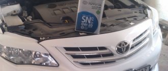
Toyota Corolla battery charging system
- Repair manuals
- Repair manual for Toyota Corolla 1992-1998.
- Battery charging system
3.3.10. Battery charging system
Battery charging circuit diagram
| 1. Battery 2. Main fuse link 3. Discharge indicator lamp 4. Ignition key 5. 10 A GAUGE fuse link | 6. Alternator 7. Built-in voltage regulator 8. US vehicles only 9. Stator winding 10. Rotor winding |
Typical location of fusible link inserts
| 1. Generator 2. Main fuse link 3. Fuse link AM2 30 A 4. Fuse link AM1 40 A | 5. Fuse link IGN 10 A 6. Fuse link GAUGE 10 A 7. Fuse link ALT-S 7.5 A 8. Fuse link ALT-H 100 A |
Circuit for checking battery discharge current
| 1. Ammeter 2. Battery 3. Disconnect the wire from terminal B 4. Voltmeter 5. Generator |
The charging system consists of an alternator, a voltage regulator built into the generator, a charge indicator circuit, a battery, a fusible jumper and connecting wires (see Fig. Battery charge circuit diagram ).
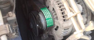
When these devices work together, power is provided to consumers such as the ignition system, lighting and alarm devices, radio, etc. The generator is driven by a belt in the front of the engine. The vehicles discussed in this Manual are equipped with generators manufactured by Nippondenso and Delco.
The voltage regulator is designed to maintain the generator voltage at a given level. When the voltage at the generator output sharply increases, the regulator prevents current surges and overloads in the power circuit.
The fusible jumper is a separate piece of wire, which is connected in series with a bundle of connecting wires from the battery and is located inside the engine compartment (see Fig. Typical location of the fusible jumper inserts ). Along with the main jumper, the charging system includes additional fuse links, which are pieces of wire with a strictly specified cross-sectional area. The cross-sectional area of the inserts is smaller than that of the wires of the circuit that the insert protects. Subsection 12.2 provides more detailed information on fuse links.
Periodic maintenance of the charging system is generally not required. However, the alternator drive belt, battery and connecting wires should be periodically inspected (inspection is carried out every 12,000 km or 6 months).
The charge indicator lamp on the instrument panel lights up when the ignition is turned on and goes out after the engine starts. If the lamp does not go out after starting the engine, then the charging circuit is faulty. Some cars are equipped with a voltmeter. If the voltmeter shows a very high or very low voltage, then the charging circuit needs to be checked (see subsection 3.3.4 )
.
Warning
When connecting the wires of the internal circuit of the car and external devices, the following precautions should be observed: – when connecting the battery to the generator, always observe the polarity of the connection;
– before repairing any part of the car using electric welding, disconnect the wires from the generator and from the battery terminal; – it is unacceptable to start the engine with the charger connected; – before connecting the charger, always disconnect the vehicle circuit cables from both poles of the battery; – be careful not to get your hands, hair, or the edges of clothing under the alternator belt while the engine is running; – the generator is connected directly to the battery, so if the generator leads are short-circuited, or if it is overloaded, an arc and fire may form; – before flushing the engine with a jet of steam, cover the generator with plastic film and secure the film with a rubber bandage. Examination
| EXECUTION ORDER |
↓ Comments ↓1. Introduction 1.0 Introduction 1.2 Model codes 1.3 Control panel 1.4. Instrument cluster 1.5. Controls and instrumentation 1.6. Starting the engine and driving the car 1.7 Technical data 1.8 Adjustment data, filling containers and liquids 1.9. Possible faults 2. Maintenance 2.0 Maintenance 2.1 Technical data 2.2 Location of components and parts 2.3 Checking fluid levels 2.4 Checking the condition of tires and tire pressure 2.5. Maintenance every 5000 km or 3 months 2.6. Maintenance every 12,000 km or 6 months 2.7. Maintenance every 24,000 km or 12 months 2.8. Maintenance every 50,000 km or 2 years 2.9 Maintenance every 100,000 km or 4 years 3. Engines 3.0 Engines 3.1. Technical data 3.2. Diesel engine 3.3. Engine electrical equipment 4. Cooling and heating systems 4.0 Cooling and heating systems 4.1 Technical data 4.2 Antifreeze 4.3 Thermostat 4.4 Fan and fan relay 4.5 Radiator and expansion tank 4.6 Coolant pump 4.7 Coolant temperature sensor 4.8 Fan unit 4.9 Heater radiator 4.10. Heater and air conditioning control panel 4.11 Air conditioner dehumidifier 4.12 Compressor 4.13 Condenser 4.14 Evaporator and expansion valve 5. Fuel and exhaust systems 5.0 Fuel and exhaust systems 5.1 Technical data 5.2 Procedure for decompressing the fuel system 5.3 Fuel pump and fuel pressure 5.4 Removing and installing the fuel pump 5.5 Fuel level sensor 5.6 Fuel lines and joints 5.7 Fuel tank 5.8 Cleaning and repairing the fuel tank 5.9 Air filter 5.10 Throttle cable dampers 5.11 Electronic fuel injection system (EFI system) 5.12 Checking and replacing EFI system units 5.13 Exhaust system maintenance 6. Toxicity reduction system 6.0 Toxicity reduction system 6.1 Technical data 6.2 Electronic control system 6.3 Electronic control unit 6.4. On-board diagnostic system 6.5. Sensors of the automatic engine control system 6.6 Gasoline vapor recovery system 6.7 Recirculation system (EGR system) 6.8 Forced crankcase ventilation system (PCV system) 6.9 Catalytic converter 7. Gearboxes 7.0 Gearboxes 7.1. Technical data 7.2. Automatic transmission 8. Clutch and axle shafts 8.0 Clutch and axle shafts 8.1 Technical data 8.2. Clutch 8.3. Half shaft 9. Brake system 9.0 Brake system 9.1 Technical data 9.2 Anti-lock brake system (ABS) 9.3 Front brake pads 9.4 Front brake caliper 9.5 Rear disc brake pads 9.6 Rear disc brake caliper 9.7 Brake disc 9.8 Rear drum brake pads 9.9 Slave cylinder 9.1 0 Brake master cylinder 9.11 Brake hoses and pipes 9.12 Hydraulic brake system 9.13 Vacuum booster 9.14 Handbrake 9.15 Handbrake cables 9.16 Brake pedal 9.17 Brake light switch 9.18 Vehicle load-sensing pressure limiting valve 10. Suspension and steering 10.0 Suspension and steering 10.1 Technical data 10.2 Suspension strut (front) 10.3 Suspension strut 10.4 Anti-roll bar (front) and bushings 10.5 Control arm 10.6 Ball joints 10.7 Steering knuckle and hub 10.8 Hub and wheel bearing (front) 10 .9 Anti-roll bar stability (rear suspension) and bushings 10.10 Suspension strut (rear) 10.11 Longitudinal link 10.12 Transverse suspension links 10.13 Hub and bearing (rear wheel) 10.14 Rear wheel hub bracket 10.15 Steering 10.16 Steering wheel 10.17 Tie rod ends 10.1 8 Steering gear 10.19 Power steering pump steering 10.20 Power steering system 10.21 Wheels and tires 10.22 Wheel alignment 11. Body 11.0 Body 11.1 Maintenance and Repair 11.2 Vinyl Trim 11.3 Upholstery and Carpets 11.4 Minor Body Damage Repair 11.5 Major Body Damage Repair 11.6 Hinges and Locks 11.7 Windshield and Fixed Windows 11.8 Hood 11.9 Trunk Lid 11.10 Rear Door (Stagon Models) ") 11.11 Rear door support pillar 11.12 Door decorative panel 11.13 Door 11.14 Door latch, lock cylinder and handles 11.15 Door window glass 11.16 Bumpers 11.17 Outside mirror 11.18 Seats 11.19 Instrument cluster frame 11.20 Glove compartment 11.21 Central decor ive panel 11.22 Steering column cover 11.23 Lower steering column trim panel 11.24 Console 11.25 Instrument panel 11.26 Radiator grille 11.27 Hood ventilation grille 11.28 Seat belts 12. Electrical equipment 12.0 Electrical equipment 12.1 Fuses 12.2 Fuseable jumpers 12.3 Circuit breakers 12.4 Relays 12.5 Turn signal/hazard light switches 12.6 Combination switch 12.7 Steering column switches 12.8 Ignition switch and lock drum 12.9 Rear window defroster switch 12. 10 Heated rear window 12.11 Radio and speakers 12.12 Antenna 12.13 Headlight bulbs 12.14 Headlights 12.15 Replacing bulbs 12.16 Daytime running lights system 12.17 Windshield wiper motor 12.18 Instrument panel 12.19 Horn 12.20 Cruise control system 12.21 Central locking system 12.22 Window lift system 12.23 Rear view mirrors with electric drive 12.24 Airbag 12.25. Electrical circuits |
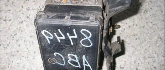
Checking an Individual Regulator
Checking the voltage regulator of the G-222 generator: 1 - battery; 2 - voltage regulator; 3 - control lamp.
As a rule, separate voltage regulators were installed on old cars, including domestic VAZs. But some manufacturers continue to do this to this day. The verification process is similar. To do this, you need to have a power supply with a voltage regulator, a 12 V light bulb, a multimeter and a directly tested regulator.
To check, you need to assemble the circuit shown in the figure. The process itself is similar to the one above. In normal condition (at a voltage of 12 V), the light bulb lights up. When the voltage value increases to 14.5 V, it goes out, and when it decreases, it lights up again. If during the process the lamp lights up or goes out at other values, it means that the regulator has failed.
Checking relay type 591.3702-01
Relay test diagram type 591.3702-01
You can also still find a voltage regulator of type 591.3702-01, which was installed on rear-wheel drive VAZs (from VAZ 2101 to VAZ 2107), GAZ and Moskvich. The device is mounted separately and installed on the body. In general, the test is similar to that described above, but the differences are in the contacts used.
In particular, it has two main contacts - “67” and “15”. The first of them is a minus, and the second is a plus. Accordingly, to check it is necessary to assemble the circuit shown in the figure. The verification principle remains the same. In normal condition, at a voltage of 12 V, the light bulb lights up, and when the corresponding value increases to 14.5 V, it goes out. When the value returns to its original value, the light comes on again.
A classic regulator of this type is a device of the PP-380 brand, installed on VAZ 2101 and VAZ 2102 cars. We provide reference data regarding this regulator.
| Adjustable voltage at regulator and ambient temperature (50±3)° C, V: | |
| at the first stage | no more than 0.7 |
| on the second stage | 14,2 ± 0,3 |
| Resistance between plug “15” and ground, Ohm | 17,7 ± 2 |
| Resistance between plug “15” and plug “67” with open contacts, Ohm | 5,65 ± 0,3 |
| Air gap between armature and core, mm | 1,4 ± 0,07 |
| Distance between second stage contacts, mm | 0,45 ± 0,1 |
Testing a three-level relay
Regulated power supply
Some car owners install on their cars, instead of standard “chocolate bars,” three-level relays, which are technologically more advanced. Their difference is the presence of three voltage levels at which the battery power is cut off (for example, 13.7 V, 14.2 V and 14.7 V). The appropriate level can be set manually using a special regulator.
Such relays are more reliable and allow flexible adjustment of the cutoff voltage level. As for checking such a regulator, it is completely similar to the procedures described above. Just do not forget about the value that is set on the relay, and accordingly, check it with a multimeter.
Generator check
There is one method by which you can check the performance of a car generator equipped with a regulator relay 591.3702-01 with diagnostic elements. It is as follows:
- disconnect the wires that went to pins 67 and 15 of the voltage regulator;
- connect a light bulb to it (excluding the regulator from the circuit);
- Remove the wire from the positive terminal of the battery.
If, as a result of these actions, the engine does not stall, then we can say that the car’s generator is in order. Otherwise, it is faulty and needs to be checked and replaced.
Reasons why the generator is not charging
- Brush wear
The most common reason why the generator does not charge the battery. This is wear on the brushes. The carbon contacts that transmit voltage from the regulator relay to the rotor windings are erased and the contact disappears. With this malfunction, the warning lamp on the instrument panel stops lighting up.
That is, when the ignition is turned on, if everything is working properly, the charging control icon should light up. The engine starts and the lamp goes out. This means that the generator is running and charging the battery.
In case there is no contact on the brushes. The light does not light up when the ignition is turned on. You can make sure that the reason is in the contacts.
The wire that goes to the regulator relay must be shorted to ground. Turn on the ignition. The light should light up. This means that there is no contact between the brushes and the slip rings. Or there is a break in the rotor winding.
If the charging indicator lamp does not light up when the wire is shorted to the housing. This means the LED has burned out. Which lights up the charging icon. Or a broken wire. It is necessary to ring the circuit from the regulator relay to the instrument panel.
2. Malfunction of the relay regulator
How to check whether the generator is charging the battery if the regulator relay integrated circuit fails. Two faults are observed. The generator stops charging. Because the relay regulator does not supply voltage to the rotor winding. Or, on the contrary, the generator voltage increases with increasing speed. This exceeds the permissible voltage for the vehicle's electrical system. This may cause the battery to overcharge. Which will lead to destruction of the plates and short circuit of the battery. Excessive voltage will also lead to failure of the vehicle's electrical equipment.
Checking the regulator relay
The relay regulator can be checked. Using a power supply capable of smoothly changing the voltage from 10 to 20 volts.
The relay regulator is connected according to the following diagram:
When the voltage increases above 14.2 _+ 0.3 volts, the light should go out. If the voltage decreases, the light comes on. This means that the relay regulator is working
3. Low tension of the generator drive belt.
If there is any doubt that the generator is not charging, the first thing to check is the tension of the drive belt. Because the resulting magnetic fluxes create resistance to rotor rotation. When the generator starts up. A loose belt slips on the generator pulley. The rotor stops rotating. The generator does not produce voltage. If you don't immediately pay attention to the belt tension. Generator diagnostics will not yield results. In fact, the fault will have to be found on a working generator. This malfunction is classified as curious. But they fall for it very often.
These are external signs of how to check whether the generator is charging the battery. If they were not enough to determine the malfunction. Next you need to remove the generator. Disassemble it and check its elements separately.
Recommendations for increasing the service life of the regulator
In order to increase the service life of the voltage regulator, it is necessary to adhere to several simple rules aimed at implementing preventive measures. Among them:
- do not allow excessive contamination of the generator, periodically inspect its condition, and, if necessary, dismantle and clean the unit;
- check the tension of the alternator belt, tighten it if necessary (either yourself or in a car service);
- monitor the condition of the generator windings, in particular, do not allow them to darken;
- check the contact on the control wire of the relay-regulator, both its quality and the presence of oxidation on it;
- Perform periodic voltage checks on the vehicle battery with the engine running.
Following these simple rules will allow you to increase the resource and service life of both the generator and the vehicle voltage regulator.
Results
Checking the voltage regulator relay is not a difficult task, and almost any car enthusiast with basic repair skills can handle it. The main thing is to have the appropriate tools for this - a multimeter, a power supply with a voltage regulator (although you can connect it to a battery with a charger), a 12 V lamp and pieces of wires for mounting the appropriate circuit.
If during the inspection you find out that the regulator is out of order, then it must be replaced (repair work is usually not carried out). The main thing is not to make a mistake when choosing it and purchase the part that is suitable specifically for your car.
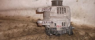
Diagnostics and typical malfunctions of Nippon Denso generators
Let's look at the diagnostics and typical malfunctions of the Nippon DENSO generator, which the TOYOTA concern installs on its cars.
These generators have a voltage rating of 14 volts and a variety of stator sizes.
Rated output currents: 45, 55, 65, 70, 75, 80, 90, 120 Amps.
The designation of the plug terminals in the block (IG, L) can be indicated on a label on the generator itself, on its cylindrical part.
In addition to ground, generators have the following external terminals:
S
— voltage regulator output for connection to the “plus” of the battery
I.G.
— voltage regulator output for powering the voltage regulator circuits through a switch
L
— output of the built-in voltage regulator for connection to the lamp for monitoring the serviceability/failure of the ignition
FR
— voltage regulator output for connection to the CU (engine control unit)
B
— power output for connection to the “positive” wire of the vehicle’s on-board network
At the outer end of the cover on the side of the slip rings there are:
- rectifier block
- voltage regulator
- brush holder
They are covered with a metal casing, which serves as both mechanical protection and heat sink.
So, one day the Client comes and says:
— I don’t have a car charger!
- And why did you decide that?
— The battery light is on on the instrument panel!
However, this is a controversial issue, because in this case there may simply be no charge control.
| photo 1 | photo 2 |
Photo 1 Charging indicator is on
Photo 2 Charging indicator does not light up
To determine what the matter is, we do the initial diagnosis:
| Photo 3 | Photo 4 |
Checking the charge level on the battery Photo 3 charging is present
Photo 4 no charging
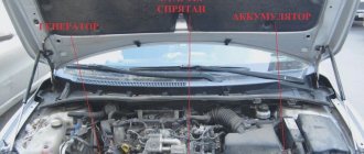
| General view of the generator on the car |
| Checking the voltage at the +B terminal |
Since we are considering generators that are installed on relatively “new” TOYOTA cars, we must remember that they have several types of connectors that differ in shape and number of wires, but their essence is the same. The photo below shows some options:
Charging system
(Scheme from the book Vista Ardeo published by Legion Avtodata)
The diagram clearly shows which output goes where. And also in the lower left corner of the diagram there are two generator connectors, “four-pin and three-pin.”
Pin S is used to monitor the voltage on the battery and the voltage on it is “feedback” for the regulator.
If there is no voltage at this pin, the generator will work, but there will be no charge control, that is, the battery lamp will be constantly on, and there will also be an “overcharge” of the battery (no feedback), that is, a voltage above 14.5 volts.
Some vehicles have a fuse called ALT S.
Also, if the voltage drops at this terminal, the battery will be “overcharged”.
Pin L is used to control the charge, that is, it is directly connected to the charging indicator lamp, it is also checked by a simple “control” relative to “-” (minus) when the ignition is turned on, the indicator and “control” lamps are half-incandescent.
If neither one nor the other is illuminated, we either have a broken wiring, or simply the charging indicator lamp has burned out.
The IG pin serves to excite the generator; if it is missing, the generator will not work.
Pin M is connected to the engine control unit; I can’t say anything about its meaning, since generators with such a regulator were not repaired.
Well, and accordingly, check the power “plus” of the generator. In its absence, the generator will simply spin “idle” without charging.
If we look at (check) terminals L and IG with the ignition on, then the voltage at terminal S is constantly present.
| Appearance of voltage regulators | Appearance of the connector on the car |
| Checking output S | If necessary, measure the voltage at pin S |
| Checking IGN output | |
| Checking output L. The test lamp should be lit at the floor level, while the charging indicator on the dashboard will be illuminated. The check becomes meaningless if the electrical circuit of the charging system does not correspond to the one shown, because on more recent TOYOTAs, charge control is organized through the control unit |
If the initial diagnosis did not reveal a lack of voltage at one or another terminal, then we decide to remove the generator after first checking the tension of the drive belt.
We put the battery on charge and remove the generator.
After removing the generator, we inspect it for mechanical damage and then proceed to disassemble the generator.
| Generator without protective cover. |
| 1. Voltage regulator 2. Brush assembly 3. Diode bridge 4. Stator 5. Rotor (field winding) |
Having disassembled the generator, we begin to check the parts.
We inspect the brush assembly for breaks, brush height and ease of movement.
We check the diode bridge using a multimeter:
| Conductivity of diodes from + to – | And lack of conductivity from – to + |
We check the resistance of the field winding (rotor), it should be from 2.5 to 4 Ohms, for reliability we check the current consumed by the field winding: 3-4.5 A.
If the winding resistance is less than normal and, as a result, the current consumption is higher than 5 Amps, the winding is changed, and the voltage regulator is changed at the same time, since it is designed for a current of no higher than 5 Amps, therefore, if the winding is faulty, the regulator “flies out” immediately.
We also check the excitation winding for a short circuit to the body; for this we use 220 volts.
A simple device for checking the short circuit of the stator and rotor windings to the housing. The test probes go into the 220 volt lamp power supply gap; accordingly, if there is a short circuit, the lamp lights up.
Next, we check the stator for a short circuit to the housing, also using 220 volts.
We inspect the stator for mechanical damage and insulation destruction.
The regulator was previously tested on a homemade stand, but then this procedure was abandoned due to its high labor intensity. If all of the above is in order, but the generator does not work, then we automatically change the regulator accordingly.
We put the generator on the stand (Novgorod company GST-K)
We check it in various modes: diagnostics, current-speed characteristic, current-voltage characteristic.
General view of the stand
| Menu | Select the desired mode |
| Regular test | Current-speed characteristic in automatic mode |
| Volt-ampere characteristics | It is also possible to view oscillograms to observe the “skew” in the phases of the generator |
Then we print out the obtained parameters and install the generator on the car.
All spare parts installed on the generator are used, that is, “contract”.
Before repairs, it is very important to talk carefully with the Client in order to try to find out and understand for yourself the reason for the failure of the generator. DENSO generators are quite reliable and rarely fail, not counting the wear of the brush assembly, and due to the negligence of car owners, other things can happen: a battery that is set to zero, an engine that has been thoroughly washed, etc.
PS This article is not a “complete technical solution”, but only reflects a special case.
Tsitsorin Dmitry Leonidovich
© Legion-Avtodata
Khabarovsk st. Bondarya GSK 171
Auto service GARAGE
8(4212)61 77 22
8