Errors p0351, p0352, p0353, p0354 are associated with faults in the ignition system. In particular, ignition coils (coils), wiring or control unit. Problems with the coil are usually caused by shorted turns on the primary or secondary winding or its breakdown. As for the wiring, this can be either a break in individual wires, damage to their insulation, or, as a consequence, a short circuit between them or to ground (housing). The most difficult case is the breakdown of the electronic control unit, in particular, the breaking off of part of the ceramic board with connectors, which is diagnosed by the electronics precisely as errors with numbers p0351, p0352, p0353 and p0354.
What does the error code mean?
Most automobile gasoline injection engines use an ignition system with individual coils. This means that each of its cylinders has its own coil, to the secondary winding of which a spark plug is connected, which supplies a spark to ignite the air-fuel mixture. Error codes p0351, p0352, p0353 and p0354 mean that there is a malfunction in the primary or secondary winding of the ignition coil of cylinder A, B, C, D (Ignition Coil A Primary/Secondary Circuit Malfunction). The last number and the letter itself indicate which coil is not working. Their signs and causes are identical, so we will consider them comprehensively.
However, all four errors will appear, for example, in a 16-valve engine, where each coil is provided separately for each cylinder. If the engine is 8-valve (for example, VAZ), then on such power units the design provides only one so-called ignition module, where only two coils are mounted. Therefore, errors will only occur with codes p0351 and p0352. Conversely, on powerful engines (for example, SUVs or sports cars), if they have six, eight or more cylinders, the number of errors may also increase (up to p0362, that is, a 12-cylinder engine).
The engine electronic control unit (ECU) determines the ignition angle for each cylinder separately, which allows a spark to be supplied at a strictly defined, suitable moment in time. This occurs by applying a signal to a power transistor in the ignition amplifier. The transistor, in turn, passes or blocks current to the primary winding of the coil. The ignition amplifier also provides feedback, when a corresponding signal is sent to the computer in the event of successful voltage transfer. If a malfunction is detected in circuit A, B, C, D of electronic ignition control by the ECM controller, then the corresponding malfunction code is set: P0351, P0352, P0353, P0354.
From english:
Decoding the error P0352 from Toyota: Manifold Air Pressure Sensor Circuit Malfunction
Make:
Toyota
Code:
P0352
Definition:
Manifold Air Pressure Sensor Circuit Malfunction
Description:
Key on or engine running;and the PCM detected the MAP sensor signal was less than 0 kPa or more than 130 kPa in the CCM test.
Cause:
- MAP sensor signal circuit is open,shorted to ground or power
- MAP sensor ground circuit is open between sensor and ground
- MAP sensor is damaged or has failed
- PCM has failed
Code generation condition
Information about the formation of OBD errors p0351, p0352, p0353, p0354 is recorded in the memory of the electronic control unit when a number of the following conditions are met:
- The car engine ignition is turned on;
- the feedback signal informs the electronic control unit that the device has not worked;
- the number of failures of individual ignition coils is constantly growing;
- a corresponding error in the ECU memory will be generated when the number of failures reaches 20 in 40 test cycles.
The information provided is relevant for the popular Chevrolet Lacetti car, however, the logic for generating errors in most cars will be similar.
Conditions for clearing code from ECU memory
Errors p0351, p0352, p0353, p0354 are deleted from memory if one of the conditions is met:
- four consecutive ignition cycles have passed during which no malfunctions in the operation of the ignition coil were detected;
- the power supply to the ECM was turned off for more than 10 seconds;
- The diagnostic code must be cleared with a scan tool.
The archive of diagnostic error codes itself disappears from the ECU memory after 40 consecutive heating cycles, provided there are no faults.
Video
Toyota Camry error codesLink to main publication
| Code 1 – 1 flash, pause, 1 flash | No faults | |
| Code 12 – 1 flash, pause, 2 flashes | The NE signal does not arrive to the ECM within a few seconds after the engine starts. The G signal does not arrive to the ECU at engine speeds from 500 to 4000 rpm. | Electrical circuit of the ignition distributor. Distributor. |
Ignition unit. Electrical circuit of the ignition unit. Starter electrical circuit. ECM block.
Fault codes for gasoline engines (Toyota)————————————————————————————Self-diagnosis codes are read by the number of flashes of the “CHECK ENGINE” indicator when the “TE1” terminals are closed ”-“E1” connector DLC1 under the hood or “TC”-“CG” connector DLC3 under the dashboard and the ignition is on.12 - Crankshaft position sensor (P0335)13 - Crankshaft position sensor (P0335, P1335)14 - Ignition system , coil No. 1 (P1300) and No. 4 (P1315)15 - Ignition system, coil No. 2 (P1305) and No. 3 (P1310)16 - Automatic transmission control system18 - VVT-i system - phases (P1346)19 - Pedal position sensor accelerator (P1120)19 - Accelerator pedal position sensor (P1121)21 - Oxygen sensor (P0135)22 - Coolant temperature sensor (P0115)24 - Intake air temperature sensor (P0110)25 - Oxygen sensor - lean signal (P0171) 27 - Oxygen sensor No. 231 - Absolute pressure sensor (P0105, P0106)34 - Turbocharging system35 - Turbo pressure sensor36 - CPS sensor (P1105)39 - VVT-i system (P1656)41 - Throttle position sensor (P0120, P0121)42 — Vehicle speed sensor (P0500)43 — Starter signal47 — Additional throttle position sensor49 — Fuel pressure sensor (D-4) (P0190, P0191)51 — Switch status52 — Knock sensor (P0325)53 — Knock signal55 — Knock sensor No. 258 — SCV drive (D-4) (P1415, P1416, P1653)59 — VVT-i signal (P1349)71 — EGR system (P0401, P0403)78 — Injection pump (D-4)89 — ETCS drive (P1125, P1126, P1127, P1128, P1129, P1633)92 - Cold start injector (D-4) (P1210)97 - Injectors (D-4) (P1215) Fault codes for diesel engines (Toyota)——————————— ———————————————–12 — Crankshaft position sensor13 — Speed sensor14 — Injection advance angle adjustment valve15 — Throttle valve servomotor17 — Control unit signal18 — Electromagnetic bypass valve19 — Accelerator pedal position sensor22 — Coolant temperature sensor24 — Intake air temperature sensor32 — Correction resistors35 — Boost pressure sensor39 — Fuel temperature sensor42 — Vehicle speed sensor96 — EGR valve position sensor Automatic transmission fault codes (Toyota)——————————————— ———————————–Self-diagnosis codes are read by the number of flashes of the “O/D OFF” indicator when the “TE1”-“E1” terminals of the DLC1 connector under the hood or “TC”-“CG” of the DLC3 connector under the hood are closed instrument panel and the ignition is on (in this case, overdrive must be allowed - “O/D OFF” is not lit).11 - Normal37 - Automatic transmission input shaft speed sensor (P1705)38 - Automatic transmission fluid temperature sensor42 - Speed sensor (or output shaft speed sensor) (P0500)44 - Speed sensor (or rear output shaft speed sensor)46 - Accumulator pressure control solenoid (P1765)61 - Speed sensor (or front output shaft speed sensor)62 - Solenoid No. 1 ( P0753)63 — Solenoid No. 2 (P0758)64 — Torque converter lockup clutch solenoid (P0773)67 — Automatic transmission input shaft speed sensor68 — Torque converter lockup clutch control solenoid73 — Center differential lockup clutch solenoid ABS fault codes (Toyota)—————— —————————————————————Reading codes (models with DLC1 connector)— Turn on the ignition.— Jumper the “TC” and “E1” terminals of the DLC1 connector.— Remove the jumper from pins “WA” and “WB” of connector DLC1.— After 4 seconds, read the code by the number of indicator flashes.— Remove the jumper from pins “TC” and “E1.”
— Install a jumper on pins “WA” and “WB”.
Resetting codes (models with DLC1 connector)— Turn on the ignition.— Jumper the “TC” and “E1” terminals of the DLC1 connector (vehicle stationary).— Press the brake pedal eight or more times in an interval of three seconds.— The indicator should display the normal code ( blink 2 times per second).— Turn off the ignition.— Remove the jumper from the “TC” and “E1” terminals.
— Make sure the ABS indicator goes out. Reading codes (models with DLC3 connector)—Jump the “TC” and “CG” terminals of the DLC3 connector.—Turn on the ignition.—After 4 seconds, read the code by the number of indicator flashes.
— Remove the jumper from the “TC” and “CG” terminals. Resetting codes (models with DLC3 connector)— Jumper the “TC” and “CG” terminals of the DLC3 connector. — Turn on the ignition.
— Press the brake pedal eight or more times within an interval of three seconds. — The indicator should display the norm code (blink 2 times per second).
— Remove the jumper from the “TC” and “CG” terminals.
Code System11 Open circuit in the solenoid valve relay12 Short circuit in the solenoid valve relay circuit13 Open circuit in the electric pump relay circuit14 Short circuit in the electric pump relay circuit21 Open circuit or short circuit in the front right wheel solenoid valve22 Open or short circuit in the front left solenoid valve wheels23 Open circuit or short circuit in the rear right (left) wheel solenoid valve24 Open circuit or short circuit in the rear left (right) wheel solenoid valve31 Malfunction of the front right wheel speed sensor32 Malfunction of the front left wheel speed sensor33 Malfunction of the rear rotation speed sensor right wheel34 Malfunction of the rear left wheel speed sensor41 Battery voltage is too high or too low43 Malfunction in the deceleration sensor circuit44 Open or short circuit in the deceleration sensor circuit49 Open in the brake light switch circuit51 Short circuit or open circuit in the electric pump power supply circuit71 Low signal level from the frequency sensor rotation of the front right wheel72 Low signal level from the front left wheel speed sensor73 Low signal level from the rear right wheel speed sensor74 Low signal level from the rear left wheel speed sensor75 Incorrect signal change from the front right wheel speed sensor76 Incorrect signal change from the speed sensor rotation of the front left wheel77 Incorrect change in the signal from the rear right wheel speed sensor78 Incorrect change in the signal from the rear left wheel speed sensor79 Malfunction of the deceleration sensor98 - Vacuum sensor in the vacuum brake booster (C1200 SRS fault codes (Toyota)————————— —————————————————–Self-diagnosis codes are read similarly to others, by the number of flashes of the “SRS” indicator when the “TC”-“E1” terminals of the DLC1 connector under the hood or “TC”- are closed. “CG” of the DLC3 connector under the dashboard and the ignition is on.
Codes should be erased when the ignition is turned off. If the codes are stored, it is necessary to carry out the cleaning procedure: - connect two wires to the “TC” and “AB” terminals - turn on the ignition and wait at least 6 seconds - alternately, once a second, short the “TC” and “AB” terminals to ground ( pause between closures - less than 0.2 seconds) - after the third closure of the “TC” output, the indicator should flash at a high frequency - this means the codes are erased.
11 — Driver air protection igniter (short to ground)12 — Driver air protection igniter (short to power)13 — Driver air protection igniter (short circuit)14 — Driver air protection igniter (open circuit)15 — Front right SRS sensor (short or open) in the circuit)15 - Front right SRS sensor (short to ground or power)16 - Front left SRS sensor (short or open circuit)16 - Front left SRS sensor (short to ground or power)31 - Malfunction of the SRS control unit51 - Igniter Passenger CB (short to ground)52 - Passenger CB igniter (short to power)53 - Passenger CB igniter (short circuit)54 - Passenger CB igniter (open circuit)61 - Driver belt pretensioner igniter (short to ground)62 - Driver belt pretensioner igniter (short to power)63 - Driver belt pretensioner igniter (short circuit)64 - Driver belt pretensioner igniter (open circuit)71 - Passenger belt pretensioner igniter (short to ground)72 - Passenger belt pretensioner igniter (short circuit) to power supply) 73 — Passenger belt pretensioner igniter (short circuit) 74 — Passenger belt pretensioner igniter (open circuit) 4WS system fault codes (Toyota)—————————————————— ————————–Self-diagnosis codes are read by the number of flashes of the “4WS” indicator when the “TC”-“E1” terminals of the DLC1 connector under the hood are closed and the ignition is on.
Code System - -11 Electronic control unit 4WS12 Malfunction of the main electric motor of the rear steering gear13 Malfunction of the steering gear control drive21 Short circuit in the main electric motor system22 Open circuit in the main electric motor system23 Blocking of the main electric motor24 Malfunction of the main electric motor31 Open circuit in the reverse motor system32 Malfunction of the electric motor reverse gear41 Malfunction of the left front wheel speed sensor42 Malfunction of the 4WS system sensor43 Incorrect operation of the 4WS system sensor
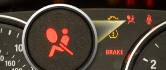
Checking the airbag system indicator Set the ignition switch to the “ACC” or “ON” position, check that the warning light comes on and goes off after about 6 seconds. Note: If the ignition switch is in the “ACC” or “ON” position and the indicator remains on or flashes, check the fault code. If the indicator sometimes lights up or remains on even when the ignition switch is in the “OFF” position, check the indicator circuit for a short circuit .
Mechanism to prevent activation of the SRS system.
1. Set the ignition switch to the “ACC” or “ON” position and wait approximately 20 seconds. 2.
Install a jumper on terminals “TC” and “E” of the diagnostic connector. Note: Incorrect pin connections may result in system failure.
3, If there is no fault, the indicator will flash 2 times per second.
. The figure shows an example of the output of codes “11” and “31”.
5. Fault codes are displayed from the smallest. If codes are not output, check the “TC” output circuit of the diagnostic connector.
6. For decoding of fault codes, see the table “SRS system fault codes”.
Signs of breakdown
External signs of error codes p0351, p0352, p0353, p0354 include:
- activation of the Check Engine warning light on the dashboard;
- misfires in one or more engine cylinders (depending on the number of errors), this leads to the engine “troubling”, operating unstably, and having an uneven idle;
- drop in engine power and deterioration in the dynamic characteristics of the machine;
- problems starting the engine.
Since such signs may indicate other problems with the engine, reading diagnostic codes with an error scanner is mandatory, this will allow you to move on to further specific checks.
More category errors
P0353P0354P0355P0356P0357P0358P0365P0367P0368P0385P0390P0392P0393P0401P0402P0403P0405P0409P0412P0415P0418P0419P0420P0430P043 EP043FP0440P0441P0442P0443P0446P0450P0451P0452P0453P0455P0456P0500P0503P0504P0505P050AP050BP0510P0511P0516P0517P0550P0552P0553P05 60P0562P0571P0575P0601P0604P0606P0607P060AP060BP060DP060EP0617P062FP0630P0657P0703P0705P0710P0711P0712P0713P0715P0717P0722P0724P07 25P0729P0741P0743P0746P0748P0750P0751P0753P0755P0756P0758P0761P0765P0766P0768P0770P0771P0773P0776P0778P0780P0781P0785See all errors →
Causes of malfunction
There are five main malfunctions that cause OBD errors p0351, p0352, p0353, p0354 to be generated in the memory of the electronic control unit. Among them:
- Faulty spark plugs or their wires. Spark plugs can fail either partially (for example, due to contamination of the electrodes) or completely, as a result of which a spark will not appear on the electrodes at all. In rare cases, a P0363 code may also be displayed.
- Ignition coil malfunction. Typically this failure is caused by the primary and/or secondary windings being shorted. Moreover, this can be either an interturn short circuit or a short circuit between the primary and secondary windings. In the first case, usually the voltage generated is not enough to ignite the air-fuel mixture, and in the second, there will be no voltage at all. Often, when a short circuit occurs, the corresponding fuses blow. Another option is a partial failure of the rubber tip of the coil, which causes a spark to simply break through to the body.
- Wiring problems. In this case, there may be breaks: between the control unit and the coil, between the coil and the spark plug, or the supply wiring. In this case, this can be either a complete break in the wires or damage to the insulation section/sections. For example, when rubbing in places of bending, exposure to extreme temperatures, and so on. In any case, diagnostics must be performed using an electronic multimeter, which allows you to find the corresponding damage.
- Control unit malfunction. This is the worst case. As mentioned above, inside the block there is a ceramic plate on which power and signal electrical contacts are installed (the design of the control unit may differ for individual car models). Due to constant overheating, the plate becomes fragile, and sometimes a situation arises when a piece of the plate with contacts simply falls off from its main part.
Another, but rather rare reason why the indicated errors with code p0351, p0352, p0353, p0354 are formed in the ECU memory are the so-called “glitches” of the control unit. In particular, its bugs in its software. This can happen, for example, after reflashing the unit, or after mechanical damage (for example, as a result of an accident).
Toyota diagnostics
There are two methods for checking for vehicle malfunctions.
The first diagnostic method
You can perform this diagnosis yourself:
When diagnosing faults on a Toyota car, the heating unit and air conditioning system must be turned off.
The Masol X channel demonstrated the procedure for performing self-diagnosis of all systems of a Toyota car.
Second diagnostic method
There is an option to check car systems using a special wire and a computer. This method is considered more accurate, but its implementation is more difficult. Finding a ready-made cable in a store will be problematic; you often have to order it.
The do-it-yourself computer diagnostic procedure for a car with an automatic transmission to find problems and malfunctions in the internal combustion engine is performed as follows:
The Garage 24 channel clearly showed the procedure for computer diagnostics of a Toyota car.
Depending on the car model, the location of the diagnostic connector may differ, but it is usually located on the rear wall of the engine compartment. To find this device you need to open the hood. Standing facing the car, you need to look at the far right corner. The protective cover is fixed using a special fastener. To open it you need to pull the “petal”.
There are a total of 20 pins on the connector, each of them is used to perform a specific task:
The remaining outputs are not so important for the car owner. The self-test procedure using a computer installs software on your computer. There are many utilities on the Internet; you can choose any program.
Toyota diagnostic output DLC1
A similar connector for TDCL diagnostics, made in a round housing
First type of errors (type 09)
This type of combination is two-digit, its parameters are as follows:
Second type of errors (type 10)
When deciphering Toyota error codes, it must be taken into account that this type of combination is unambiguous, its parameters are as follows:
The Kaz Bek channel talked about independently performing self-diagnosis of a Toyota car.
Diagnosis of errors p0351, p0352, p0353, p0354
If the scanner detects one or more of the above ignition coil or module error codes, further verification must be performed as follows:
- Programmatically delete error information from the electronic unit’s memory. This must be done in order to prevent accidental formation of errors in the block. If, after rebooting the ECU, errors are generated again, further comprehensive diagnostics must be continued.
- Next, you need to check the ignition coil indicated by the error code. This applies to both primary (primary if a common primary winding is used) and secondary windings. To do this, you need to disconnect them from the wiring and check the integrity of the winding using an electronic multimeter. It also makes sense to check the mechanical integrity of the corresponding coils, the presence of damage, contamination, and integrity of contacts.
- Check the integrity of the wires. To do this, it is advisable to get a diagram of the car's electrical contacts. This will make it easier to find out whether individual wires are broken and whether they are shorted to each other or to ground. For the corresponding check, an electronic multimeter is used, switched to the “continuity” mode. In particular, it is necessary to check the integrity of the wires between the ignition coil and the computer. To do this, the wires are disconnected at both ends for “dialing”.
- Checking the electronic control unit. First of all, you need to check whether the contacts on the ceramic plate discussed above have broken off. If everything is in order with the contacts, then you need to check the logic of the ECU. However, it is better not to check it yourself, since this is a responsible undertaking, and it is better to delegate it to specialists from a car service center, preferably an official one.
- Check for good ground contact at the ignition coil/coils. It also makes sense to check for corrosion and oxides at the contact points.
- Check the intake manifold for vacuum leaks. If such a leak occurs, ignition of the air-fuel mixture will become impossible in some cylinders, which will lead to misfire.
Technical description and interpretation of error P0352
This diagnostic trouble code (DTC) is a generic powertrain code. The P0352 code is considered a common code because it applies to all makes and models of vehicles. Although the specific repair steps may vary slightly depending on the model.
The COP (coil-on-plug) ignition system is used in most modern engines. There is a separate coil for each cylinder, controlled by the PCM (powertrain control module).
This eliminates the need for spark plug wires by placing the coil directly above the spark plug. Each coil is allocated two wires. One of them is power, usually coming from an electrical distribution center. The other wire is the coil driver circuit from the PCM.
The PCM grounds/disconnects this circuit to activate or deactivate the coil. The coil driver circuit is monitored by the PCM for faults.
If an open or short is detected in the number 2 coil driver circuit, a P0352 code may occur. Additionally, depending on the vehicle, the PCM may also disable the cylinder fuel injector.
How to fix the problem?
Possible efforts to eliminate errors code 0351, 0352, 0353, 0354:
- replacing spark plugs and/or their wires connecting them to the ignition coils;
- replacing the ignition coil/coils, since repair of this unit is hardly possible in most cases;
- replacement or repair of power and/or signal wires on coils, electronic control unit, spark plugs (replacement is more preferable, since electric current with significant voltage passes through power wires);
- replacing or reflashing the software of the electronic control unit; in rare cases, repairs are possible, but it is better to entrust it to professionals.
Some car enthusiasts, when an ignition coil fails, do not buy it entirely (especially if they have to replace the original one with an inexpensive Chinese one), but instead order a new tip (if the design of the coil allows such a replacement). The fact is that the tip may become unusable over time due to natural reasons. When replacing, be sure to use high-temperature Teflon grease (specially designed for installing ignition coil tips) so that the new tip does not remain in the well on the spark plug.
Please note that to perform diagnostics and repairs, it is often necessary to have professional repair equipment, such as an oscilloscope and a professional scanner for the operation of individual engine components. And you need to “ring” the wires by first disconnecting the negative terminal from the battery.
The listed faults are not critical, but it is still advisable to get rid of them as soon as possible. This is due to the fact that since the corresponding errors cause the ignition system to operate incorrectly, there is a significant load on the coils, spark plugs and wires, and this leads to increased wear and tear and a decrease in the overall service life.
P2237
P2237 – open circuit in the oxygen sensor (A/F) pumping current circuit, P2238 – low current in the oxygen sensor (A/F) pumping current circuit (1 row 1). We are talking about a lambda probe installed before the catalyst, which is located next to the engine. This error may not affect the behavior of the car, but fuel consumption will increase. We would like to warn against replacing this sensor with a non-original one.
The lambda probe, located before the catalyst near the engine, is replaced only with the original one. The second sensor installed after the catalytic converter can be replaced with a universal one. Using this head will allow you not to remove the heat shield when replacing failed lambda probes.
