TEST SEQUENCE
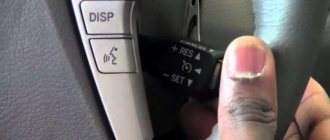
Reset the DTC (See page Click here).
Turn the ignition switch (IG) ON and check that the multiplex CAN bus DTCs are not output.
Start driving, increase your speed to 3 km/h (2 mph) or more, and check that the speed sensor DTCs (brake control system DTCs) are not output (See page Click here and Click here).
Remove fuse ECU-IG1 from the instrument panel distribution block.
Measure the resistance of the fuse.
Disconnect ECU connector E67.
Measure the voltage at the harness side connector.
Disconnect ECU connector E67.
Measure the resistance of the connector on the wiring harness side.
Reset the DTC (See page Click here).
Start driving, increase your speed to 3 km/h (2 mph) or more, and check that the same DTC is output.
Possible causes and tips for troubleshooting problems that led to the error.
Possible causes and tips for troubleshooting problems that led to the error:
Causes:
Low battery. Defective battery. Faulty charging system. Power supply diagram.
Troubleshooting Suggestions:
If there is a problem with the power supply circuit of the brake actuator assembly (electronic skid control unit), the skid control ECU issues a diagnostic trouble code (DTC) and disables the fail-safe function. If the voltage supplied to the terminal is not within the DTC detection threshold due to a fault in the battery and alternator circuit, for example, the DTC is stored.
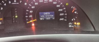
Error codes for the SRS security system in Toyota cars
The codes are read with the ignition on based on the number of times the SRS lamp lights up. In connector DLC1, contacts TC and E1 must be closed, and in DLC3, a jumper is installed between pins TC and CG.
Error codes must be erased when the ignition is turned off. If the codes are stored in memory, follow these steps:
DTC Car chassis operating errors C1241
On our resource you can ask questions and share your own experience in troubleshooting problems associated with error C1241. By asking a question within a few days you will be able to find the answer.
Taking into account the fact that OBD2 errors in the operation of the engine or other electronic systems of the car do not always directly indicate a non-functioning element, and the fact that for different brands and models of cars the same error can arise as a result of a malfunction of completely different elements of the electronic system, we have created this algorithm for assistance and exchange of useful information.
We hope, with your help, to form a cause-and-effect relationship for the occurrence of a particular OBD2 error in a specific car (make and model). As experience has shown, if we consider a specific make and model of a car, then in the vast majority of cases the cause of the error is the same.
If the error indicates incorrect parameters (high or low values) of any of the sensors or analyzers, then most likely this element is working, and the problem must be looked for, so to speak, “upstream”, in the elements whose operation is analyzed by the sensor or probe.
If the error indicates a constantly open or closed valve, then you need to approach the issue wisely, and not thoughtlessly change this element. There may be several reasons: the valve is clogged, the valve is jammed, the valve receives an incorrect signal from other faulty components.
Errors in the operation of the OBD2 engine and other vehicle systems (ELM327) do not always directly indicate a non-functioning element. The error itself is indirect evidence of a malfunction in the system, in a sense a hint, and only in rare cases a direct indication of a faulty element, sensor or part. Errors (error codes) received from a device or scanner require correct interpretation of the information, so as not to waste time and money on replacing working elements of the car. The problem often lies much deeper than it seems at first glance. This is due to the fact that information messages contain, as mentioned above, indirect information about the disruption of the system.
Here are a couple of general examples. If the error indicates incorrect parameters (high or low values) of any of the sensors or analyzers, then most likely this element is working, since it analyzes (produces certain parameters or values), and the problem must be looked for “upstream”, so to speak, in elements whose operation is analyzed by a sensor or probe.
If the error indicates a constantly open or closed valve, then you need to approach the issue wisely, and not thoughtlessly change this element. There may be several reasons: the valve is clogged, the valve is jammed, the valve receives an incorrect signal from other faulty components.
Another point that I would like to note is the specifics of a particular brand and model. Therefore, if you recognize an error in the operation of the engine or other system of your car, do not rush to make hasty decisions, but approach the issue comprehensively.
Our forum was created for all users, from simple car enthusiasts to professional auto electricians. A drop from each will be useful to everyone.
The first character is commonly called the DTC alpha indicator. This symbol indicates which part of the vehicle has a problem. The choice of symbol (P, B, C or U) is determined by the control unit being diagnosed. When a response is received from two blocks, the letter for the block with higher priority is used. Only four letters can be in the first position
The second symbol is the most controversial. It shows that it has identified the code. 0 (known as P0 code). A basic, open fault code defined by the Association of Automotive Engineers (SAE). 1 (or code P1). A fault code defined by the vehicle manufacturer.
The third character indicates the system where the fault is detected. Less is known about this symbol, but it is one of the most useful. Looking at it, we can immediately tell which system is faulty, without even looking at the error text. The third character helps you quickly identify the area where the problem is occurring without knowing the exact description of the error code.
-Fuel-air system. — Fuel system (for example, injectors). — Ignition system. - An auxiliary emissions control system, such as an Exhaust Gas Recirculation System (EGR), an Air Injection Reaction System (AIR), a catalytic converter, or an Evaporative Emission System (EVAP). ). — Speed control or idle control system, as well as related auxiliary systems. - On-board computer system: engine control module (Power-train Control Module - PCM) or controller area network (CAN). — Transmission or drive axle. — Transmission or drive axle.
By mistake P1150 see posts below!
********************************************
| Added after 364 days 10 hours 1 minute |
climate error 24 - right sun sensor
*************** It is better to remain silent and be considered a fool than to speak up and immediately dispel all doubts about this.
All errors TOYOTA 4RUNNER, ALLEX, ALLION, ALPHARD, ALTEZZA, ARISTO, AURION, AURIS, AVALON, AVENSIS, AYGO, BB, BELTA, BLADE, BREVIS, CALDINA, CAMI, CAMRY, CELICA, CELSIOR, CENTURY, COROLLA, ECHO, ESTIMA , FJ CRUISER, FORTUNER, FUNCARGO, GT86, HARRIER, HIACE, HIGHLANDER, HILUX, INNOVA, IPSUM, iQ, ISIS, IST, KLUGER HYBRID, KLUGER V, LAND CRUISER, LAND CRUISER PRADO, MARK, MARK X, MATRIX, MR 2 , NADIA, NOAH, OPA, PASSO, PLATZ, PREMIO, PREVIA, PRIUS, PROBOX, PROGRES, RACTIS, RAUM, RAV4, RUSH, SAI, SEQUOIA, SIENNA, SIENTA, SOLARA, TACOMA, TUNDRA, URBAN CRUISER, VANGUARD, VELLFIRE, VENZA, VERSO, VITZ, VOLTZ, VOXY, WILL CYPHA, WILL VS, WINDOM, WISH, YARIS.
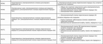
Table with errors
Full description of error codes for Toyota cars:
General faults
The following components are subject to diagnosis:
- all sensors installed on wheels;
- anti-slip system control unit;
- wires from the ABS control module to the controllers and control unit;
- contacts on the regulators.
Transmission faults
- malfunction of the speed shift sensor;
- gear drive failure;
- damage to the cable or one of the contacts on it;
- software malfunction of the control unit or use of an old version of software (software);
- lack of communication between the engine and gearbox control modules.
Possible causes of the malfunction:
- selection mechanism stroke sensor;
- incorrect operation of the selector drive unit and speed switch assembly (system electric motor);
- automatic transmission module malfunction;
- damage or wear to the shift joint or fork rod.
- malfunction of the drive device for selecting and switching speeds in the assembly;
- short circuit in the transmission electric motor line;
- problems in the operation of the TCM module.
More details on what to check:
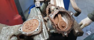
- Screen filters for the solenoid valve of the variable valve timing drive. These elements can be clogged or torn, and sometimes they are not installed correctly.
- Leakage of motor fluid at the seating surfaces of the gas distribution valve drive unit seals.
- Interruption of the supply of engine fluid to the solenoid valve of the drive mechanism.
- Integrity of the timing belt for wear.
Possible causes of the problem:
- incorrect compression in the engine cylinders;
- air leak;
- damage to the cylinder head gasket or head;
- faulty or clogged mass air flow sensor;
- failure of the lambda probe or damage to one of the contacts on the devices;
- fuel filter clogged;
- injector malfunction.
- failure or incorrect functioning of the electric pneumatic valve for controlling the turbocharger;
- break or short circuit on the vacuum control line;
- malfunction of the turbocharger device;
- breakdown of the recirculation system valve;
- damage to vacuum pipes or leakage;
- malfunction of the power unit control unit.
- malfunction of the fuel filter device;
- leakage or loosening of the fuel line clamps (you need to check the integrity of the nut for tightening the fuel pump cover and housing);
- breakdown of the fuel pump device.
Possible causes of the malfunction:
- battery discharge or damage;
- malfunction of the ignition switch or Start/Stop system;
- regular use of low-quality fuel;
- problems with the immobilizer;
- malfunction of the anti-theft system;
- critical engine failure;
- clogged one of the filters that affects startup;
- faulty injectors or oxygen sensors.
Sensor malfunctions
To resolve the issue, it is recommended to do the following:
- Check the integrity of the connectors on the block connecting the sensor to the dashboard. Perhaps the contact has come loose and needs to be reconnected.
- Diagnose the integrity of the cable through which the sensor is connected to the instrument cluster.
- Check the quality of the connection between the controller and the transmission unit.
- Carry out diagnostics of contacts for short circuits.
- malfunction of the boost pressure controller, sensor parameters are not within the range of normalized values;
- problems in the functioning of the turbocharger control drive unit.
- damage to the sensor power wiring or the bulbs installed in the brake lights;
- failure of the relay or safety device of the optical elements;
- damage to the fuse socket or contacts;
- malfunction of the sensor installed on the brake pedal;
- problems with the control unit.
- malfunction of the left or right front engine speed controller;
- damage to the wiring supplying the regulator;
- malfunction of the rotor speed mechanism;
- errors made when installing the sensor;
- Malfunction of the brake actuator control module assembly (ABS).
Electrical and electronic faults
Possible causes of the malfunction:
- the heating element has failed;
- the lambda probe fuse is blown;
- the wiring supplying the sensor is damaged, or a short circuit has occurred in the electrical circuit;
- the contact on the controller power supply has oxidized;
- The ECM motor control unit has failed or is not working correctly.
- stopping the engine when idling;
- difficulty starting the engine;
- “triple” of the power unit when driving uphill;
- RPM surges.
Possible causes of the malfunction:
- battery discharge;
- damage to the battery, which led to leakage of electrolyte and its inoperability;
- oxidation of the battery terminals or damage to the clamps;
- generator device malfunction;
- failure of the regulator relay;
- Damage or breakage of the drive belt.
Possible causes of the problem:
- failure of the clutch release actuator device;
- the smoothness of the fork or release bearing is impaired;
- failure of the clutch basket;
- use of non-original spare parts to repair the system;
- errors made when installing parts;
- using a control unit with outdated software.
- line damage or short circuit on the reverse light switch wire;
- failure of the switching mechanism travel controller;
- breakdown of the travel sensor of the selection mechanism;
- a malfunction of the TCM module or a software failure in its operation;
- Reverse light switch is broken.
- the control unit has not calibrated the zero position of the deceleration controller;
- the vehicle position was not stabilized during calibration;
- the SRS control module is faulty or operates intermittently;
- the control unit has failed or is not functioning correctly.
- broken or damaged line of the speed shift solenoid valve SR;
- SLU is shorted or disconnected.
damage to the wires on the instrument cluster or disconnection of contacts;
malfunction of the main wiring harness in the engine compartment;
failure of the left front anti-skid sensor;
Possible causes of the problem:
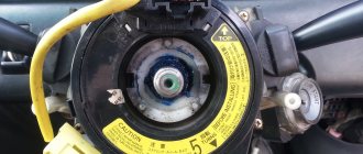
damage or wear of the harness with electrical circuits connected to the instrument cluster;
malfunction of the twisted wire assembly;
failure or disconnection of the contact from the horn button;
- the anti-skid system control module detects an impulse of a break or damage to the power line of the rear left squib;
- breakdown of the airbag knock sensor;
- failure of the control module or software failure of the SRS device.
- short circuit in the power supply wiring of the driver's knee airbag knock sensor;
- failure of the device's squib;
- breakdown or software malfunction in the operation of the SRS control module.
- Communication error between the engine control module and the ID code block. A detailed diagnosis of the wiring harness is required.
- Communication line failure. It is recommended to diagnose the ECM module.
- Identification element differences detected during the exchange of information between the identifier module and the ECM. It is necessary to check the operation of the modules.
To diagnose, you need to do the following:
- Check the battery. The cause of the problem may be its discharge, which causes the generator to work in increased mode, which leads to an increase in voltage. You need to make sure that there is no damage to the battery case, as well as the integrity of the contact clamps.
- Perform diagnostics on the generator drive belt. If the product is worn out, it must be replaced.
- Check the operation of the generator device. The cause of the problem may be a faulty regulator relay.
To find the cause, perform the following steps:
- the sensor itself is checked - the contact may have come off the device;
- diagnostics of the electrical circuit connected to the sensor is performed;
- The parking radar control unit is diagnosed.
Two-digit Type 9 codes
Possible causes of the malfunction:
- damage to the pins on the connection block;
- cable break or wear of the insulating layer;
- malfunction of the EFI unit itself;
- software problem;
- Battery malfunction.
- candles;
- coils;
- high-voltage wires;
- distributor.
Fault codes are considered for the following Toyota models:
- 4Runner
- Avensis T25 (Avensis T25);
- Avalon (Avalon);
- Auris (Auris);
- Aristo (Aristo);
- Brevis (Brevis);
- Caldina (Kaldina);
- Carina (Karina);
- Cami (Kami);
- Camry V40 (Camry);
- Chaser (Chaser);
- Corolla MMT, Ceres, SV40 (Corolla);
- Corona Premio (Crown Premio);
- Crown 1G FE (Crown);
- Estima (Estima);
- Fielder;
- Isis (Isis);
- Ipsum (Ipsum);
- Gracia (Grace);
- Granvia (Granvia);
- Highlander (Highlander);
- Hilux (Hilux);
- Land Cruiser 200 (Land Cruiser);
- Majesta (Majesta);
- Mark, Mark2 (Mark);
- Nadia (Nadia);
- Noax (Noah);
- Passo (Passo);
- Platz
- Prado (Prado);
- Previa (Previa);
- Prius (Prius);
- Rav4 (Rav 4);
- Soarer (Sorer);
- Surf
- Town;
- Verso (Verso);
- Vista (Vista);
- Vitz (Vitz);
- Wish (Wish);
- Yaris (Yaris);
- Windom (Windom);
How to diagnose the error?
The self-diagnosis process for Toyota vehicles can only be performed using connectors DLC1 and DLC2.
The test block is made in the form of a small plastic module equipped with a lid. Depending on the car model, the location of the connector may vary, but usually it is located in the engine compartment on the left side. On the block cover there is the inscription “Diagnostic”. In older versions of Toyota, the device is located next to the battery.
For Toyota Karina cars 1992-1997, as well as Corona and Mark 1992, error codes can only be read by reading the blinking LEDs. In newer versions of vehicles, the DLC2 module is located in the vehicle interior. It can be seen under the center console panel or near the driver’s feet, under the steering wheel. The module is made in the form of an oval or circle. The diagnostic process consists of closing certain contact elements of the block, which must be connected in a specific sequence.
Algorithm for checking:
- The protective plastic cover is removed from the connector. On the reverse side of the lining there is a special diagram showing the terminals of the block.
- Using a piece of wire, cable or paper clip, you need to make a jumper that is mounted between the pins numbered TE1 and E1.
- The key is inserted into the lock and the ignition is activated. When conducting diagnostics, the heating and air conditioning systems must be turned off.
- During the test, you need to look at the Check Engine LED indicators (for diagnosing the power unit) and at O/D (for the gearbox). The user must record the number of blinks of the light bulb, as well as the intervals.
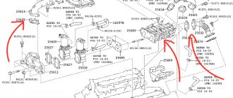
Pin designation on the DLC diagnostic block
You can determine the absence of malfunctions in the operation of the internal combustion engine (ICE) and gearbox by two symptoms:
- LED lights blinked evenly at the same interval and duration 11 times;
- The Check indicator blinks continuously and evenly at intervals of 4.5 seconds.
If there is no contact diagram on the cover or it has been erased, you can determine the required pins as follows:
- The car's ignition system turns on.
- One of the contact elements of the light indicator is connected to any standard engine ground bolt.
- The second output of the light bulb is connected in turn to each contact of the diagnostic block.
- At the moment when the Check indicator lights up on the dashboard, we can conclude that the required pin has been found.
To read the code you need to count the LED blinks:
- when a combination appears, the LED blinks quickly, lights up for a few tenths of one second;
- the time interval between decimal and unit readings will be no more than 1.5 s;
- the pause between each subsequent code will be 2.5 seconds;
- series of codes for various problems are separated by a pause of 4.5 s.
Video: Toyota car self-diagnosis
The JDM27 channel in its video showed the process of diagnosing the engine and automatic transmission of a Toyota car.
Self-diagnosis - step-by-step instructions
Professional car diagnostics at a specialized service center is not cheap. In addition, many car owners simply do not have the opportunity to use such services, since they live far outside large cities, and they have no desire to turn to “garage” specialists.
In such cases, self-diagnosis methods come to the rescue. Only basic skills are needed, so even beginners can figure it out. For example, to check engine operation, the procedure is performed in the following order:
If your car uses a DLC3 connector, you need to close contacts TC and CG.
How to reset the error?
To clear a fault code, perform the following steps:
- The car's ignition system turns on.
- On the diagnostic block, to reset the memory of the control unit, contacts TC and E1 are closed.
- Over the next three seconds, the user must press the brake pedal at least 8 times.
- Then you need to make sure that the LED indicator blinks with a pause of 0.5 seconds.
- The ignition is turned off and the jumper is disconnected from the pins. If the error codes are successfully cleared, the anti-lock brake indicator will not illuminate on the instrument panel.
You can use a computer to remove combinations of faults. If the diagnostics were performed using a laptop, software is used to reset the memory.
Deciphering Avensis fault codes
Unlike the first generation T22, in the second release of T25 from 2004-2005, two-digit blink codes appeared that can be read during self-diagnosis and checked with the table above or in the user manual. The self-diagnosis procedure looks like this:
The number of flashes indicates the code. The gap between two ciphers exceeds 2 seconds. Between tens and ones - one and a half. An interval smaller than this indicates units.
Error C1201: Toyota Avensis
When diagnosing this error code, a mechanic will do the following:
Common errors when diagnosing code P0205
A modern car is equipped with a large number of electronic sensors that monitor the correct operation of various systems. If a malfunction is detected, they send relevant information to the electronic engine control unit. It stores a specific error or fault code, which can be read during diagnostics. If the breakdown is serious, the Check Engine indicator lights up on the instrument panel. Thanks to this, the driver can correct the problem in a timely manner. In this article we will look at the most common error codes for Toyota cars. You will also learn how to perform diagnostics yourself.
The cost of diagnosing errors for Ford at service stations in Moscow and St. Petersburg
Approximate prices for computer diagnostics of faults:
| City | Company name | Address | Phone number | Price |
| Moscow | North Motors | St. Dubninskaya, 83 | +7 | 2500 rub. |
| Silver elephant | St. Pyalovskaya, 7 | +7 | 3500 rub. | |
| Saint Petersburg | Automagic | St. Uchitelskaya, 23 | +7 | 2000 rub. |
| ClinliCar | Bolshoy Sampsonievsky Ave., 61k2 | +7 | 3000 rub. |