Self-diagnosis of climate control. Works on most Japanese cars and is sometimes very useful. Process: 1. Stop the engine. 2. Simultaneously press and hold the “AUTO” and “Internal air circulation” buttons on the climate control. 3. Turn on the ignition. After checking the indicators, sensor diagnostics will automatically begin. 4. The result of the sensor diagnostics is displayed in the window displaying the set temperature. If there are 2 or more codes, the display starts with the smallest one. 5. To diagnose the drives, press the “Internal air circulation” button. Checking the drives should be carried out on a warm engine. To slow down the test, press the heated front window button. At intervals of 1 second. the damper actuators, fan and relay will operate. To enter the sensor diagnostic mode, press “AUTO”. 6. To complete the diagnostics, press the “OFF” button. Clearing the memory: After troubleshooting, clear the memory: while diagnosing the sensors, press the “Heated front window” (FRONT) and “Heated rear window” (REAR) buttons simultaneously.
Error codes: 00 - No errors 11 - Interior temperature sensor* 12 - Ambient temperature sensor* 13 - Evaporator temperature sensor* 14 - Coolant temperature sensor* 21 - Sunlight sensor (passenger side)* 22 - Lock sensor compressor** 23 — Pressure sensor (refrigerant).*** 24 — Sunlight sensor (driver's side)* 31 — Air mixture damper position sensor (passenger's side)* 32 — Air intake damper position sensor* 33 — Air Outlet Damper Position Sensor Circuit 41 - Damper Control Servo (Passenger Side)* 42 - Damper Control Servo* 43 - Air Outlet Damper Control Servo Motor Circuit 46 - Damper Control Servo (Driver Side) 51 - Compressor Solenoid Circuit 62 - Humidity Sensor air (not in Camry) 71 - A/C Inverter High Voltage Power Resource System Malfunction 72 - A/C Inverter High Voltage Output System Malfunction 73 - A/C Inverter Start-up Signal System Malfunction 75 - A/C Inverter Cooling / Heating System Malfunction 76 - A/C Inverter Load System Malfunction 77 - A/C Inverter Low Voltage Power Resource System Malfunction 97 - BUS IC Communication Malfunction 98 - Communication Malfunction (A/C Inverter Local) 99 - Multiplex Communication Circuit Note: *: Malfunction this sensor or climate control control unit; The wiring or connectors between this sensor and the climate control are damaged. **: This sensor or climate control unit is faulty; The wiring or connectors between this sensor and the climate control are damaged; The compressor drive belt is damaged or not adjusted; The compressor electromagnetic clutch sensor is faulty; The air conditioning compressor is faulty (or the compressor is blocked); The engine control module (ECM) is faulty. ***: This sensor or climate control control unit is faulty; The wiring or connectors between this sensor and the climate control are damaged; The compressor is faulty (or the compressor is blocked); Leakage, lack of refrigerant or incorrect (lower or higher than normal) pressure in the system. —————————————————————————————————————————————————— ——— Codes 21 and 24 may pop up if diagnostics are carried out in a dark room or at night. Due to loss of connection with the instrument panel, code 71 cannot be displayed on it. —————————————————————————————————————————————————— ——— What is “compressor blocking”? Many people do not understand this point. The principle of correct operation is simple. When the compressor is OFF, the accessory drive belt rotates only the accessory drive belt pulley. If the compressor needs to be turned ON, the electromagnetic clutch is activated (the compressor is locked with the pulley and begins to rotate). The brain receives a signal from a sensor (similar to the ABS sensor) that the compressor is turned on and rotating. This sensor then transmits pulses to the ECM equal to the engine speed. If the ratio between the compressor and engine speeds deviates by 20% or more from normal operation, the ECM turns off the air conditioning compressor and the indicator begins to flash with period
1 p. Data on the operating status of the compressor is transmitted by the ECM to the air conditioning control unit via a multiplex data transmission system (CAN and BEAN buses).
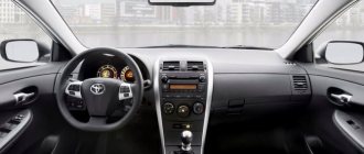
Japanese cars are distinguished not only by increased reliability, but also by comfort. And one of the proofs of this is the climate control in the Camry, which automatically provides a comfortable temperature for the driver and passengers. The basis of a car’s climate system is a control unit, which also controls the temperature and direction of airflow. But it does not last forever, and may fail during operation.
Climate control Camry
Climate features in Camry
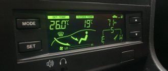
Depending on the body model, cars are equipped with a single-zone, dual-zone, and in the latest modifications, a three-zone climate control system. The latest version is the most functional and easy to use. There are several types of climate control units:
- On the Camry 30, climate control was usually installed in an old style, without a display. But there are later "thirties" with LCD displays;
- 40th car bodies are equipped with newer modifications of units with both single-zone and dual-zone control; they are equipped with a liquid crystal display and push-button control;
- Camrys in the 50 body are equipped with a modern unit with a display controlled using buttons.
Few people know, but units with displays allow for full diagnostics of sensors and actuators used by the car’s climate control system.
First, let's estimate the cost of purchasing a radiator
If you are moving forward, the original Toyota Camry V40 radiators in various articles have the following image:
| Toyota | 88460-06210 | 30102 rub. |
| Toyota | 8846006070 | 55,115 rubles |
| Toyota | 8846033100 | 30,984 rubles |
The difference in price is due to engine power and transmission type (models with automatic transmission cost higher). Above, for article number 8846006070 there are non-original replacement options depending on the engines:
READ Chevrolet Lacetti windshield replacement
| Nissense | 94757 | 2,4-3,0 | 5516 rub. |
| AVA | TO5319 | 2,0-3,0 | 5146 rub. |
| Ella | 8FC 351 307-391 | 2,4-3,0 | 4786 rub. |
| Valeo | 818109 | 2,4-3,0 | 5693 rub. |
The time difference in the price of spare parts and components is always alarming, and it is not easy to understand where such “inexpensive” analogues come from. The answer is simple: Toyota produces the Camry 40 in several modifications, and after receiving contracts for the supply of the conveyor, all manufacturers begin to produce “spare parts”. This is the same thing that Toyota supplies, but only for the free market and at completely different prices.
The decision on how much to pay for a new radiator will be up to the buyer, but there are some things to keep in mind in this case. It is simply an evaporator, which is a closed container in which the liquid changes temperature, and many parts manufacturers make such components and components perfectly.
Self-diagnosis procedure
This function is available if the climate control on the Camry 40 is equipped with a unit with an LCD display. On older versions of units, diagnostics can only be carried out using a car scanner by connecting to the standard connector located near the steering column.
Self-diagnosis procedure
We are trying to carry out self-diagnosis of the climate systems in the car, you need to perform the following steps:
- Turn off the engine, turn off the ignition.
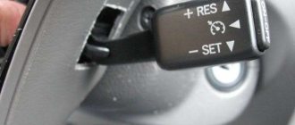
- Simultaneously press the Auto button on the climate control panel and the button that activates internal air circulation.
- While holding the buttons, turn on the ignition. At the same time, all indicators located on the remote control display will begin to blink, which indicates the start of the self-diagnosis process.
- After checking the display and diagnostics of the sensors, an error code will be displayed on the display in the place where the temperature is normally displayed.
- If 2 or more errors occur, they are displayed alternately, starting with the smallest code.
The climate control on the Toyota Camry is equipped with a considerable number of electric drives, the functionality of which can be checked by switching to self-diagnosis mode. To do this you need:
- Start the system self-diagnosis process as described above, then press the button that activates air circulation inside the cabin. Important: diagnostics must be performed on a fully warmed-up internal combustion engine.
- During the test, various fan operating modes will turn on alternately, with a delay of 1 second, and the dampers will open/close.
- You can increase the interval for changing modes by pressing the windshield defogger button.
- To exit the test mode for drives, relays and fans, press the AUTO button - in this case, the control unit will switch to the sensor test mode.
The diagnosis is completed by pressing the Off button.
Climate control for Toyota Camry
The climate control control unit on the Toyota Camry supports the memory clearing function. It should be carried out after eliminating errors that arose during the self-diagnosis process. It is performed as follows:
- The control unit is put into diagnostic mode.
- Press the front window heating and rear window heating buttons at the same time.
- The error memory has been cleared.
There are many reasons why the climate control on a Camry 50 or 40 shows errors during self-diagnosis: from missing contact to sensor failure.
Possible malfunctions that occur during climate control operation are as follows:
- sensor malfunction. Fixed by replacing it;
- control unit malfunction. Often, to fix the problem, it is enough to simply disassemble it and solder all the contacts;
- Damaged electrical wiring or sensor connectors. This often occurs as a result of unqualified intervention in the electrical equipment of a car;
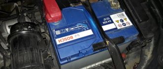
- weak compressor drive belt tension or damage. In this case, you need to check the integrity of the belt;
- failure of the electromagnetic clutch sensor installed in the compressor;
- compressor failure or blockage;
- leakage or lack of refrigerant, or its level does not correspond to that established by the car manufacturer;
- lack of contact with the instrument panel or engine ECU.
Troubleshooting
Self-diagnosis of climate control may be required if the device fails and the normal level of comfort in the car interior is disrupted.
The main sources of problems are:
- sensors;
- fan;
- compressor.
It is not always possible to visually determine the presence of faults. For a simple check, sometimes it is necessary to completely disassemble the system. If the breakdown is hidden in the wrong place, the driver will be seriously disappointed, because he had to do such work in vain.
In order not to needlessly disassemble the interior, modern systems on cars have provided a self-diagnosis function for climate control. Automakers install approximately identical devices on cars, which simplifies their installation during vehicle assembly, further repairs and maintenance.
There may be some differences between car climate control systems. But mostly it's about power and design. Their operating principle is the same.
Before checking the climate control in cars, be sure to read the operating manual for your particular car. The manufacturer provides recommendations for maintenance and repair, and instructions for enabling the self-diagnosis mode on specific climate control equipment.
Scanner check
Some people test climate control using a plug-in diagnostic scan tool. In this case, the work has the following sequence:
- turn off the car ignition;
- connect an external scanner to check;
- find the recirculation button and the opposite key (on the right or left in the corner);
- simultaneously press the key with the ignition settings without starting the engine.
After this, the scanner will begin reading data, and records about the start of diagnostics will appear on the screen. The device will automatically check it and display errors in the form of digital codes.
But external scanners do not always provide accurate information. Plus, modern climate systems allow you to launch a self-diagnosis mode without the participation of external testers and check everything in a matter of minutes.
Checking without a scanner
Self-test instructions may vary slightly. But usually there is no fundamental difference. Therefore, we suggest looking at the procedure for launching diagnostics using the example of climate controls installed on Toyota cars.
If you want to check the current status of the equipment, then proceed in the following sequence:
- turn off the ignition;
- hold down the Auto button and the button to select the air intake mode (internal or external) and turn on the engine;
- the panel indicators should light up 4 times, and the interval between them will be 1 second;
- To exit the diagnostic mode, press the Off button;
- when the indicators are checked, diagnostics of the condition of the climate control sensors will begin;
- to check the drives, hold down the air intake mode selection key;
- The drives should be checked when the engine is warm;
- to slow down the test mode, press the button to turn on the heated windshield;
- at one-second intervals, the damper drives, relays and system fan will start to turn on;
- to switch to diagnostic mode, press the Auto button;
- you will see the result of the test on the screen where the temperature is displayed;
- if the display shows 2 codes or more, the indication is carried out from the lower value;
- To complete the procedure, click on Off.
A little about compressor blocking
Blocking the compressor does not mean that it is jammed as a result of foreign objects getting inside.
Compressor blocking
The fact is that when the electromagnetic clutch is turned off, only the pulley rotates with the drive belt. And after pressing the AC key on the climate control unit, its signal activates the electromagnetic clutch, connecting the pulley and the rest of the compressor mechanism. Its rotation frequency is controlled by a special sensor, which transmits signals to the ECU. If a discrepancy between the compressor rotation speed and the engine speed is detected by more than 20%, the climate control unit will automatically turn off the electromagnetic clutch, thereby stopping the compressor. In this case, the AC indicator light on the climate panel will begin to flash once per second.
Therefore, if, when you turn on the air conditioner, warm air blows from the air ducts, and the climate control on the Toyota Camry 40 shows an AC error, then the first thing you should do is check the condition of the belt and its tension.
P0137, P0157
P0137, P0157 – low voltage in the oxygen sensor circuit (bank 1, bank 2 sensor 2). Causes of errors P0137, P0157:
- open circuit, break in the heated oxygen sensor circuit, row 1,2 sensor 2,
- faulty lambda probe (heated oxygen sensor),
- air/fuel mixture sensor bank 1,2 sensor 1,
- leakage from the exhaust gas system.
New and Old Lambda Sensor If, during active air-fuel ratio control, the target ratio is rich but the heated oxygen sensor output voltage is less than 0.21 V (lean), the ECM treats this as an excessively low sensor output voltage and sets DTC P0137 or P0157 . During active air-fuel ratio control, if the target ratio is lean but the output voltage is greater than 0.59 V (rich), the ECM considers this to be an excessively high sensor output voltage and sets DTC P0138 or P0158.
If replacing the sensor did not bring results, then the technicians could have replaced the wrong sensor (this happens often), or the problem is not in the sensor, but in the circuit or in an exhaust gas leak. Check all connectors; they may have oxidized or moisture may have gotten into them. Visually inspect the wiring to see if its integrity is damaged. If the circuit is visually in order, then check its operation using an oscilloscope.
Catalog number 1 of the oxygen sensor installed before the catalyst.
Replacing the climate control unit
If the climate control regulator on a Camry sv20 is broken, then by replacing it you can simultaneously solve two problems - increase the functionality of the car’s climate system and improve the interior. The fact is that in terms of dimensions the climate from 30 is completely similar to the “twenty”. There is a slight difference in the wiring, but the working diagrams for connecting the climate control unit from another car model are more than enough.
In a similar way, you can answer the question of how to make climate control on a Camry America - just replace the faulty unit with a European one. But it is worth considering that errors may occur during self-diagnosis, since American car models are equipped with additional sensors.
Engine overheating occurs when the cooling system malfunctions
When the engine overheats, the coolant temperature gauge needle approaches the red zone
If the engine overheats, unpleasant consequences can occur: breakdown of the head gasket, warping of the head and, as a result, difficult engine repairs
Checking the cooling system
If the temperature gauge needle has moved into the red zone, but no clouds of steam are escaping from under the hood, you need to turn on the maximum interior heating mode. This is necessary to reduce the temperature of the fluid in the engine cooling system
You need to turn on the hazard warning lights and move to the edge of the roadway, and if possible, then outside the roadway
The engine should be idled for a couple of minutes with the heater on at full power.
Do not stop the engine immediately! The only condition is to maintain the tightness of the cooling system. If the hose bursts or comes off or another leakage point forms other than fluid escaping from under the expansion tank plug, the engine must be stopped immediately
After stopping the overheated engine, local overheating of the coolant begins at the points of its contact with the most overheated engine parts and the formation of vapor locks. This phenomenon is called heat stroke
- Stop the engine
- Open the hood and inspect the engine compartment
When inspecting the engine, pay attention to the presence of coolant in the expansion tank, the integrity of rubber hoses, radiator, thermostat
Do not immediately open the radiator cap. The liquid in the cooling system is under pressure; opening the plug can cause burns.
You also need to look under the instrument panel on the front passenger side to see if there is a leak underneath or traces of coolant leaking from the heater core.
A broken hose can be temporarily repaired using adhesive tape.
A radiator leak, thermostat or heater malfunction is difficult to eliminate on site, so you need to add water to the cooling system and monitor the temperature gauge while driving, periodically restoring the level in the cooling system
Do not add cold water to an overheated engine. The engine must cool down with the hood open for at least 30 minutes.
A broken or loose accessory drive belt almost always leads to engine overheating. If the belt is intact, you need to check its tension
The engine may overheat if the thermostat malfunctions, which regulates the flow of fluid in the cooling system through or past the radiator (to speed up the warm-up of a cold engine)
To check the thermostat, with the engine warm, check by touch the temperature of the hose connecting the thermostat to the radiator. If the radiator hose is cold, the thermostat is faulty, there is no circulation through the radiator
A common cause of engine overheating is the failure of the electric radiator fan.
We start the engine, monitor the temperature and pay attention to whether the cooling system fan turns on when the engine overheats
The reason the fan does not turn on may be a blown fuse, a faulty switch relay...
...oxidized contacts in the wiring block, burnt-out additional fan resistance or burnt-out electric motor
If the fan motor does not turn on, replace the fuse link (A) in the fuse and relay mounting block installed in the engine compartment
If after replacing the fuse link the fan does not start working, you need to check the fan motor
To do this, you need to take two additional wires and supply power directly from the battery to the electric motor.
If the electric motor starts to work, the wiring, fuses or fan relay are faulty
Advice
There are two valves installed in the radiator cap - inlet and outlet. The exhaust valve plays a big role in maintaining engine temperature
It maintains an excess pressure in the system of at least 78.5-122.7 MPa (0.80-1.25 kgf/cm2), ensuring an increase in the temperature at which the coolant begins to boil and preventing intense vaporization. If the valve is jammed in the closed position, overheating causes a significant increase in excess pressure - more than 0.2 MPa (20 kgf/cm2), which can lead to a rupture of the radiator or failure of one of the hoses.
Valve jamming in the open position leads to premature boiling of the coolant
You need to wash the radiator cap with running water once a year. If in doubt, replace the plug.
Obviously, if you remove the radiator cap on an overheated engine and this action coincides with thermal shock, then boiling of the liquid and the formation of air locks in the cooling system will be guaranteed
Periodically, you need to blow out the radiator cells with a stream of compressed air to remove dirt, adhering insects and road debris from the surface of the radiator. This way you can partially restore the efficiency of the radiator
given: - Camry v40 - “climate” is fully automatic - the temperature outside is below zero - the temperature set in the cabin is from 19 to 21. - the air conditioner indicator does not light up, but I did not turn it off manually, i.e. If necessary, the air conditioner will turn on automatically
If I turn on recirculation under these conditions (when there is a smokehouse in front, for example), then simultaneously with the indicator for turning on recirculation, the air conditioner indicator lights up and they both begin to flash synchronously in an incomprehensible algorithm.
Moreover, it does not always happen there even at approximately the same temperature outside, even during one trip, i.e. At first it blinks, but the next time you turn it on everything is ok, the indicators are constantly on, or vice versa - at first everything is ok, and then they start blinking synchronously (the blinking intervals are different).
What does this Morse code mean?
PS TFM has not smoked yet.
Here is a video where you can see that the air conditioner works great at -9.
The video shows how immediately after turning on the recirculation, the air conditioner automatically turned on, after which the “recirculation” and “air conditioning” buttons blinked synchronously, but the blinking did not continue and everything worked as normal.
sometimes it happens that they continue to blink further - this is exactly what I wrote about at the very beginning, but this is not on the video, I’ll take it again later.
then why isn't it always like that? Then why, at the same temperature for the same trip, it either works normally, or breaks Morse code.
then why does it blink synchronously with recirculation.
no, I don't think that's the issue.
for example, this morning at -4 it blinked when I turned it on, and in the evening at -5 everything was ok.
and if you turn off the air conditioner manually, but leave the “climate” in automatic mode, then the recirculation will not blink, but this is understandable.
it depends on whether the climate turns on the air conditioner and what the evaporator temperature is. If the climate turns on the air conditioner and the evaporator temperature is above zero, a signal goes to the compressor relay and it turns on the compressor. In general, the climate control lamps blink to indicate an error. There may be no pressure in the system (freon leakage), the compressor is faulty. Since the error is floating, I assumed the compressor relay. But at the link below, five people write that this signaled to them that the cabin filter was clogged.
version doesn't work. > when recirculation is turned on, the air conditioner should turn on (not just a light bulb)
It shouldn’t, but in AUTO mode this is exactly what happens, as indicated by the light.
> And since with a minus he cannot do this
Maybe. turns on. tonight at -5 everything was ok, the air conditioner turned on and off synchronously with the recirculation, nothing blinked.
Computer diagnostics of Toyota Camry 40 cars is a powerful tool in determining the location of a car malfunction.
Diagnostics must be performed when the on-board computer message “Check VSC System” appears.
To carry out diagnostic work, specialized (dealer) or universal equipment is required. As a result of diagnosing the devices of the Toyota Camry 40, error codes are issued. Most car scanners independently decipher error codes.
How to understand what is wrong and how to fix it?
Task No. 1. One of the problems with this equipment is that one of the functions fails, for example, when you turn on the fan, this function works on the passenger side but not on the driver side. Also, the system may not respond to temperature control, but after a while it will start working normally.
READ Renault symbol replacement heater radiator
The best option would be to contact a service center and install hardware diagnostics, but first you can check its operation yourself. To do this, turn off the ignition and hold down the automatic mode and recirculation buttons, then turn on the ignition and release the previously pressed buttons. You should see an error code on the monitor and determine the cause of the failure.
Task No. 2. Another fairly common reason is air conditioning failure. It stops cooling the air, turns on the compressor, runs for 5 minutes and stops cooling. At the same time, the freon level and pressure are normal.
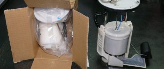
If you notice similar changes in the performance of your machine's equipment, you should consider checking the thermistor located on the evaporator fins. By assessing the temperature, it sends a signal to the air conditioning computer to turn off the compressor if the evaporator is about to freeze.
Task No. 3. Cold or barely warm air blows into the front seat passenger's legs, and the driver is very hot at the same temperature.
In this situation, you can try replacing the cabin filter and disconnecting the battery and then diagnose the problem.
If warm air starts blowing when the air conditioning is on and the climate control shows an AC error, be sure to check the condition and tension of the belt.
In some cases, it may be advisable to replace the climate control unit in your vehicle. This will help improve the functionality of your car's climate control system and even improve its interior. You can replace the faulty unit with a European one.
Task No. 4. Often Toyota Camry 40 stops using climate control on the steering wheel. This happens in cases where the driver tries to repair the steering wheel, removes it and puts it back in place. Under the steering wheel there is a cable with wires that are responsible for the functions, they can be accidentally damaged or cut, and the cable itself can break, causing the above problem.
Task No. 5. Warm air blows, blows onto the passenger seat, the air is slightly warm, and then at speed while the radiator pipes are hot. If all the air ducts are sealed and no problems are visually detected, the cause may be in the radiator.
This car model is quite modern, and its equipment is quite complex. Therefore, so that you do not have to spend money on replacing it or expensive repairs, do not be lazy to diagnose it in a timely manner.
Source
And for the air conditioner to work properly, all elements of this complex system must work. The peculiarity of Japanese cars is that the manufacturer randomly changes the elements of the air conditioning system depending on the configuration, so even one model has several options.
How to perform computer diagnostics on Camry 40
Various scanners are used to diagnose blocks and components of Toyota Camry v40 cars. Optimal scanning is performed using dealer devices. You can use universal professional and semi-professional diagnostic devices. Engine diagnostics can be performed using simple scanners such as ELM327.
In this case, some specific errors in the engine management system may not be detected. Common errors in the OBDII protocol will be fully identified. In most cases, this is enough to identify most faults.
The sequence of diagnostic work is approximately the same for all devices:
- Turn off the ignition.
- Connect the vehicle diagnostic connector to the scanner.
- Connect the scanner to a computer (if it is not a single unit) or to a smartphone, as in ELM
- If using a Bluetooth connection, make it using a smartphone.
- Download the diagnostic program to your computer (with the exception of integrated Launch scanners). Select the car model, year of manufacture, scan type.
- Turn on the car ignition and wait until the on-board computer performs self-diagnosis.
- Start scanning.
- As a result of scanning, the program will display error codes that have accumulated in the scanned control units.
- Write down all error codes. Some programs automatically decipher error codes, sometimes in Russian. In this case, the transcript must also be recorded. Sometimes some errors are not decrypted by the diagnostic program. This can be done later using search engines or on forums.
- Remove all errors. Perform diagnostics again. After completing these steps, only valid errors will remain. Data about previously recorded errors will be erased; perhaps some sensor was disconnected and then connected again. Some of the inactive errors may appear again after several kilometers of driving the vehicle.
- Record valid errors.
- During professional diagnostics, the next stage is a dynamic scan, as a result of which it is possible to determine: ignition timing, instantaneous fuel consumption, temperature conditions, and other important parameters of engine operation. To perform dynamic diagnostics, the engine must be started.
- All units of the car are scanned in the same way: the brake system, automatic transmission, climate control, immobilizer, body control unit and others.
- At the end of the diagnostic work, the ignition is turned off and the scanner is disconnected from the diagnostic connector.
Next, we begin to analyze the errors and their arrangement.
Video
Toyota Camry error codesLink to main publication
| Code 1 – 1 flash, pause, 1 flash | No faults | |
| Code 12 – 1 flash, pause, 2 flashes | The NE signal does not arrive to the ECM within a few seconds after the engine starts. The G signal does not arrive to the ECU at engine speeds from 500 to 4000 rpm. | Electrical circuit of the ignition distributor. Distributor. |
Ignition unit. Electrical circuit of the ignition unit. Starter electrical circuit. ECM block.
Fault codes for gasoline engines (Toyota)————————————————————————————Self-diagnosis codes are read by the number of flashes of the “CHECK ENGINE” indicator when the “TE1” terminals are closed ”-“E1” connector DLC1 under the hood or “TC”-“CG” connector DLC3 under the dashboard and the ignition is on.12 - Crankshaft position sensor (P0335)13 - Crankshaft position sensor (P0335, P1335)14 - Ignition system , coil No. 1 (P1300) and No. 4 (P1315)15 - Ignition system, coil No. 2 (P1305) and No. 3 (P1310)16 - Automatic transmission control system18 - VVT-i system - phases (P1346)19 - Pedal position sensor accelerator (P1120)19 - Accelerator pedal position sensor (P1121)21 - Oxygen sensor (P0135)22 - Coolant temperature sensor (P0115)24 - Intake air temperature sensor (P0110)25 - Oxygen sensor - lean signal (P0171) 27 - Oxygen sensor No. 231 - Absolute pressure sensor (P0105, P0106)34 - Turbocharging system35 - Turbo pressure sensor36 - CPS sensor (P1105)39 - VVT-i system (P1656)41 - Throttle position sensor (P0120, P0121)42 — Vehicle speed sensor (P0500)43 — Starter signal47 — Additional throttle position sensor49 — Fuel pressure sensor (D-4) (P0190, P0191)51 — Switch status52 — Knock sensor (P0325)53 — Knock signal55 — Knock sensor No. 258 — SCV drive (D-4) (P1415, P1416, P1653)59 — VVT-i signal (P1349)71 — EGR system (P0401, P0403)78 — Injection pump (D-4)89 — ETCS drive (P1125, P1126, P1127, P1128, P1129, P1633)92 - Cold start injector (D-4) (P1210)97 - Injectors (D-4) (P1215) Fault codes for diesel engines (Toyota)——————————— ———————————————–12 — Crankshaft position sensor13 — Speed sensor14 — Injection advance angle adjustment valve15 — Throttle valve servomotor17 — Control unit signal18 — Electromagnetic bypass valve19 — Accelerator pedal position sensor22 — Coolant temperature sensor24 — Intake air temperature sensor32 — Correction resistors35 — Boost pressure sensor39 — Fuel temperature sensor42 — Vehicle speed sensor96 — EGR valve position sensor Automatic transmission fault codes (Toyota)——————————————— ———————————–Self-diagnosis codes are read by the number of flashes of the “O/D OFF” indicator when the “TE1”-“E1” terminals of the DLC1 connector under the hood or “TC”-“CG” of the DLC3 connector under the hood are closed instrument panel and the ignition is on (in this case, overdrive must be allowed - “O/D OFF” is not lit).11 - Normal37 - Automatic transmission input shaft speed sensor (P1705)38 - Automatic transmission fluid temperature sensor42 - Speed sensor (or output shaft speed sensor) (P0500)44 - Speed sensor (or rear output shaft speed sensor)46 - Accumulator pressure control solenoid (P1765)61 - Speed sensor (or front output shaft speed sensor)62 - Solenoid No. 1 ( P0753)63 — Solenoid No. 2 (P0758)64 — Torque converter lockup clutch solenoid (P0773)67 — Automatic transmission input shaft speed sensor68 — Torque converter lockup clutch control solenoid73 — Center differential lockup clutch solenoid ABS fault codes (Toyota)—————— —————————————————————Reading codes (models with DLC1 connector)— Turn on the ignition.— Jumper the “TC” and “E1” terminals of the DLC1 connector.— Remove the jumper from pins “WA” and “WB” of connector DLC1.— After 4 seconds, read the code by the number of indicator flashes.— Remove the jumper from pins “TC” and “E1.”
— Install a jumper on pins “WA” and “WB”.
Resetting codes (models with DLC1 connector)— Turn on the ignition.— Jumper the “TC” and “E1” terminals of the DLC1 connector (vehicle stationary).— Press the brake pedal eight or more times in an interval of three seconds.— The indicator should display the normal code ( blink 2 times per second).— Turn off the ignition.— Remove the jumper from the “TC” and “E1” terminals.
— Make sure the ABS indicator goes out. Reading codes (models with DLC3 connector)—Jump the “TC” and “CG” terminals of the DLC3 connector.—Turn on the ignition.—After 4 seconds, read the code by the number of indicator flashes.
— Remove the jumper from the “TC” and “CG” terminals. Resetting codes (models with DLC3 connector)— Jumper the “TC” and “CG” terminals of the DLC3 connector. — Turn on the ignition.
— Press the brake pedal eight or more times within an interval of three seconds. — The indicator should display the norm code (blink 2 times per second).
— Remove the jumper from the “TC” and “CG” terminals.
Code System11 Open circuit in the solenoid valve relay12 Short circuit in the solenoid valve relay circuit13 Open circuit in the electric pump relay circuit14 Short circuit in the electric pump relay circuit21 Open circuit or short circuit in the front right wheel solenoid valve22 Open or short circuit in the front left solenoid valve wheels23 Open circuit or short circuit in the rear right (left) wheel solenoid valve24 Open circuit or short circuit in the rear left (right) wheel solenoid valve31 Malfunction of the front right wheel speed sensor32 Malfunction of the front left wheel speed sensor33 Malfunction of the rear rotation speed sensor right wheel34 Malfunction of the rear left wheel speed sensor41 Battery voltage is too high or too low43 Malfunction in the deceleration sensor circuit44 Open or short circuit in the deceleration sensor circuit49 Open in the brake light switch circuit51 Short circuit or open circuit in the electric pump power supply circuit71 Low signal level from the frequency sensor rotation of the front right wheel72 Low signal level from the front left wheel speed sensor73 Low signal level from the rear right wheel speed sensor74 Low signal level from the rear left wheel speed sensor75 Incorrect signal change from the front right wheel speed sensor76 Incorrect signal change from the speed sensor rotation of the front left wheel77 Incorrect change in the signal from the rear right wheel speed sensor78 Incorrect change in the signal from the rear left wheel speed sensor79 Malfunction of the deceleration sensor98 - Vacuum sensor in the vacuum brake booster (C1200 SRS fault codes (Toyota)————————— —————————————————–Self-diagnosis codes are read similarly to others, by the number of flashes of the “SRS” indicator when the “TC”-“E1” terminals of the DLC1 connector under the hood or “TC”- are closed. “CG” of the DLC3 connector under the dashboard and the ignition is on.
Codes should be erased when the ignition is turned off. If the codes are stored, it is necessary to carry out the cleaning procedure: - connect two wires to the “TC” and “AB” terminals - turn on the ignition and wait at least 6 seconds - alternately, once a second, short the “TC” and “AB” terminals to ground ( pause between closures - less than 0.2 seconds) - after the third closure of the “TC” output, the indicator should flash at a high frequency - this means the codes are erased.
11 — Driver air protection igniter (short to ground)12 — Driver air protection igniter (short to power)13 — Driver air protection igniter (short circuit)14 — Driver air protection igniter (open circuit)15 — Front right SRS sensor (short or open) in the circuit)15 - Front right SRS sensor (short to ground or power)16 - Front left SRS sensor (short or open circuit)16 - Front left SRS sensor (short to ground or power)31 - Malfunction of the SRS control unit51 - Igniter Passenger CB (short to ground)52 - Passenger CB igniter (short to power)53 - Passenger CB igniter (short circuit)54 - Passenger CB igniter (open circuit)61 - Driver belt pretensioner igniter (short to ground)62 - Driver belt pretensioner igniter (short to power)63 - Driver belt pretensioner igniter (short circuit)64 - Driver belt pretensioner igniter (open circuit)71 - Passenger belt pretensioner igniter (short to ground)72 - Passenger belt pretensioner igniter (short circuit) to power supply) 73 — Passenger belt pretensioner igniter (short circuit) 74 — Passenger belt pretensioner igniter (open circuit) 4WS system fault codes (Toyota)—————————————————— ————————–Self-diagnosis codes are read by the number of flashes of the “4WS” indicator when the “TC”-“E1” terminals of the DLC1 connector under the hood are closed and the ignition is on.
Code System - -11 Electronic control unit 4WS12 Malfunction of the main electric motor of the rear steering gear13 Malfunction of the steering gear control drive21 Short circuit in the main electric motor system22 Open circuit in the main electric motor system23 Blocking of the main electric motor24 Malfunction of the main electric motor31 Open circuit in the reverse motor system32 Malfunction of the electric motor reverse gear41 Malfunction of the left front wheel speed sensor42 Malfunction of the 4WS system sensor43 Incorrect operation of the 4WS system sensor
Checking the airbag system indicator Set the ignition switch to the “ACC” or “ON” position, check that the warning light comes on and goes off after about 6 seconds. Note: If the ignition switch is in the “ACC” or “ON” position and the indicator remains on or flashes, check the fault code. If the indicator sometimes lights up or remains on even when the ignition switch is in the “OFF” position, check the indicator circuit for a short circuit .
Mechanism to prevent activation of the SRS system.
1. Set the ignition switch to the “ACC” or “ON” position and wait approximately 20 seconds. 2.
Install a jumper on terminals “TC” and “E” of the diagnostic connector. Note: Incorrect pin connections may result in system failure.
3, If there is no fault, the indicator will flash 2 times per second.
4. If there is a malfunction, the indicator will flash at a variable frequency. Identify trouble codes.
. The figure shows an example of the output of codes “11” and “31”.
5. Fault codes are displayed from the smallest. If codes are not output, check the “TC” output circuit of the diagnostic connector.
6. For decoding of fault codes, see the table “SRS system fault codes”.
Engine error codes, possible malfunction
After performing diagnostic work, it is necessary to obtain as much information as possible about the suspected malfunction. For example, computer diagnostics showed error P0032. According to the table below, it is interpreted as exceeding the maximum current in the heater circuit of the first lambda probe. You should not immediately buy a new sensor (in Camry it costs more than 3,000 rubles).
First of all, you need to check the electrical wiring that leads to it. The Camry, like most new gasoline cars, has two oxygen sensors (lambda probes) - one before and one after the catalyst. They are heated, that is, there is a spiral that heats the sensor to enter working condition. It is possible that the sensor is faulty, the coil is shorted, and the diagnostics shows error 0032. But in most cases, the cause of this malfunction is a short circuit in the wiring leading to the lambda probe. It is laid in close proximity to the exhaust manifold, which heats up to a temperature of more than 300 degrees Celsius. If the PVC insulation is destroyed, the wiring may have a short to ground on the vehicle. In this case, error P0032 may appear. It is possible that the error will disappear at the time of diagnosis, but then it will appear again while driving, so it is better to check the quality of the insulation.
Below is a breakdown of the main engine error codes and their possible causes.
Mechanical damage to the air conditioning system can immobilize the vehicle
We don't want to scare anyone, but a lot of things go together in a modern car, so some problems with the air conditioning system can cause the engine to run abnormally.
If we talk about Toyota Camry, then the cause of failure may be the bearing, the cost of which is from 8 to 10 euros. Given the design of the shaft, it never fails immediately, starting to make sounds with increased wear. The safety margin of the assembly is large, so even after complete wear, the shaft will rotate for some time. But there is no need to lead to this.
Toyota officially states that the compressor is not disconnected and if problems occur, the entire unit must be replaced. This is not actually the case, and if you know exactly which unit is on the machine, you can replace the bearing cheaply and have the system running like new.
However, it is better to leave this level of work to professionals, and in order for the air conditioner to work correctly, pay more attention to those parts of the system that we mentioned above.
Source
Automatic transmission fault codes, possible faults
Automatic transmission repair is one of the most complex car system repairs. High-quality maintenance and repair of an automatic gearbox is impossible without computer diagnostics. It should be noted that diagnostics allows you to determine mainly errors in sensors, solenoids (solenoid valves), and control circuits.
As is the case with engine management system components, you should not immediately start replacing, for example, an automatic transmission solenoid. It is necessary to gain access to it (sometimes after removing the automatic transmission and disassembling it), then measure its electrical resistance. For most solenoids, the resistance value is in the range from 10 to 25 ohms.
You cannot replace solenoids without cleaning the chips and changing the oil in the automatic transmission. If the automatic transmission is more than 10 years old, you can simultaneously perform routine maintenance using the appropriate overroll kit. Computer diagnostics do not report mechanical faults of components in the form of codes.
Assess the level of the problem before purchasing new parts and components.
The air conditioning system consists of 9 main elements and suddenly fails only when the fan fails. But this is a rather rare occurrence, so before solving the replacement problem, we will consider the following points:
- Cleaning engine radiators and air conditioning. After cleaning the cell cooling elements, efficiency usually increases by 15-25% after 3 years of vehicle operation;
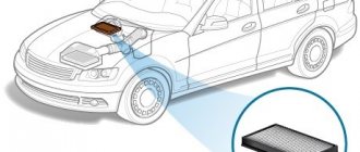
- Timely replacement
of air filters. In hot summers, a clogged filter can reduce cooling system efficiency by 40% (and add moisture); - Pressure testing costs money, so after 3 years of operation it is better to dry and fully charge the air conditioner. The difference in price is small, but refilling does not allow cleaning the evaporator, so the efficiency of the system will still decrease;
- Visually inspect and clean all air intake points. Sometimes a simple brush can restore normal interior climate.
The second level of problems with the air conditioning system is mechanical - extraneous noise, vibration, various sounds and other signs of increased mechanical wear. These problems need to be addressed quickly, rather than waiting for a breakdown, which will lead to more expensive repairs.
ABS fault codes, possible faults
ABS system error codes make repairs much easier. If the anti-lock brake system malfunction indicator light comes on, it means that it has become completely inoperable. Continuing to drive, especially on slippery roads, is dangerous. In most cases, the cause of the malfunction may be the failure of one of the sensors. If the error code shows a malfunction in the circuit of any sensor, for example, the rear left one, again, you should not immediately start replacing it. Most often this is due to damage to the electrical wiring leading to it. Sometimes there are up to three wiring faults along the way to the rear sensors.
If the error code corresponds to an incorrect signal value for a particular sensor, the working area may be dirty, or the gap may be increased due to small stones.
Before replacing the sensor, it should be tested using a multimeter. The working sensor has a resistance in one of the directions from 700 to 1500 Ohms.
Below are error codes with explanations and possible malfunctions.
P0351, P0352, P0353, P0354, P0355, P0356
Ignition coil errors, the last two can only appear on Toyota V6 engines, for example, 2GR-FE. Reasons for these codes:
- faulty ignition coil,
- faulty wiring leading to the coils,
- broken electronic control unit.
To accurately determine the malfunction, use an oscilloscope to measure the electrical signal from the ignition coil that showed the error. If you don't have an oscilloscope, you can swap the potentially faulty coil with another. For example, there is an error P0351, we moved the coil from the first cylinder to the second, now the scanner shows P0352 - the problem is in the coil, but if the code remains the same P0351 - the wiring or ECU is faulty.
Airbag fault codes
If there is a message on the dashboard about a malfunction of the airbag system, you should definitely check which elements and sensors are faulty or there is no communication with them. The resistance of the airbag and belt pretensioner squib can be checked with a multimeter, it is about 2 ohms. Error codes with explanations are given in the table.
P0172
Error P0172 - Air/fuel mixture too rich. Causes:
- air intake system,
- faulty injectors,
- not working correctly mass air flow sensor,
- fuel pressure is outside acceptable limits,
- exhaust gas leak,
- the problem is in the circuit or in the oxygen sensor itself,
- ECU.
To make an accurate diagnosis, contact an experienced specialist. One option to eliminate the error is to replace the VVT-I valve.
Other electrical fault codes
Complete computer diagnostics of Camry 40 cars greatly simplifies repair and maintenance. Fault codes are universal for all vehicles (with some minor differences in the error codes for vehicles for the North American market).
Main reasons
Temperature sensor (using the example of Hyundai Tucson).
The first thing to do is call self-diagnosis. If this does not bring results, turn on the ignition, then pay attention to the display - the error number should light up there. If the number “18” lights up, this indicates a malfunction of the temperature sensor (short circuit).
The device connector is located near the left leg of the front seat passenger (it is easy to recognize by its white color).
After disconnecting, there are two options - install a new sensor or replace it with a 2.2 kOhm resistor.
After this, you should call the self-diagnosis again. If error “17” appears, this indicates high resistance (diagnosed as an open circuit).
The next time you turn the ignition on and off, the air conditioning starts working.
Many car owners complain about the situation when, after winter, the car’s climate control does not work, and trying to turn the button on and off does not produce results. One of the reasons is a freon leak.
Here it is worth taking into account the following points:
One way to check is to use a tester, which is placed on the service terminals of the air conditioner.
Based on the measurement results, conclusions are drawn about how much freon the system needs.
Next, the cylinder is connected and refueling is performed (without disassembling the system).
Remember that before replenishing the working gas, the cause of the leak must be investigated and repaired.
If the climate control does not work, for example, it turns off on its own while driving, and the display does not light up, the cause may be a blown fuse.
The location of these elements may vary from vehicle to vehicle. A malfunction can be recognized by the complete dysfunction of the device - the climate control display does not light up, and the device does not respond to commands.
The solution is to replace the failed insert with a fusible one.
Stove fan chip.
One of the reasons why climate control does not work is problems with the stove fan chip. In this case, the system screen often works normally and without errors.
After turning on, the required button lights up, but the air conditioner does not turn on. In this case, the pressure in the system is normal, as is the freon level.
The reason may be a lack of voltage at the outputs of the climate control unit, one of which goes to the EM valve of the accelerated idle cycle, and the other is in the air conditioner clutch activation circuit.
If you apply 12 volts directly to the clutch, it is activated, and the climate control itself performs its assigned function.
A detailed inspection shows that all elements are intact, the board tracks are not damaged and ring.
The first thing that is recommended is to use a similar control unit. If the climate control still does not work, the problem is in the heater fan chip.
The device does not see the fan speed, which leads to a malfunction. Special attention to the connector should be given to owners of Laguna cars (Renault Laguna), in which the contact group often burns or the fan as a whole may burn out.
The fan is usually mounted using four bolts and is installed under the glove compartment.
In Renault cars, the connector consists of ten black contacts, of which two are not used. In this case, four connections are power, and four more are control.
Malfunction of the “twist” (using the example of Mazda Axel 3).
There are situations when an attempt to regulate climate control using a “twist” does not produce results - the device does not work, and the temperature is not regulated (the previously set value remains).
The first thought that comes to mind is problems with the contact connection.
To identify the cause and eliminate the breakdown, you will need a pair of screwdrivers (regular and Phillips), as well as superglue.
The algorithm of actions is as follows:
After completing the assembly, check whether the climate control is working - the “crank” should perform the tasks assigned to it.
The system is not activated (using the example of the Opel Astra).
Let's consider the situation. An attempt to turn on the climate control when the outside temperature is high does not yield anything - the unit does not work and continues to blow warm air into the cabin.
The manual for the car says that you just need to set the desired temperature using the “twist” and after some time the system will blow cold air. But that did not happen.
After a trip to the service station, it turned out that the air conditioning was not turned on. But how to activate it if the button with the “snowflake” is missing?
It is believed that the system should operate automatically. This is wrong. In fact, climate control is turned off for the winter, and by spring you need to turn it on yourself by entering the CLIMATE menu.
To do this, you need to click on the large “twist” and activate the “AC” square. If this is the reason, the system will work properly.
Fuse on the clutch (using the example of the Opel Astra).
There are situations when the climate control is activated, the “tick” is set, but the unit still does not work - warm air is supplied to the cabin.
The first solution that comes to mind is to sign up for diagnostics, but in 99% of cases the problem is in the clutch fuse.
It is enough to replace it, and the air conditioner should work. The service station will most likely force you to change the compressor, which will cost a large sum.
The air conditioner radiator is cracked.
Another breakdown that owners of cars with climate control encounter is damage to the air conditioner radiator (the appearance of a crack).
Regardless of the reason, the only solution is to contact a service station, repair under warranty, or replace the unit at your own expense.
Depending on your vehicle model, you may need to order a part.
The compressor valve is faulty (using the example of Volkswagen Passat B6, 2.0, turbodiesel).
Let's consider the situation. The climate control works, but the cold air flow is too weak. And if in the spring this state of affairs seemed to be the norm, with the arrival of the summer heat the low efficiency of the unit becomes noticeable.
Diagnostics at a service station shows a compressor malfunction and the need for its repair or replacement. The specialists set a price tag of 14,000 rubles for replacing the radiator, dryer, compressor and flushing the system.
Repeated diagnostics showed that the compressor works and cools, but does not work for long. At the same time, after a while the fan begins to drive a warm flow.
A small amount of freon was pumped into the system, after which the climate control worked briefly and failed again.
Checking the system for leaks showed no problems. Using a special device, it was possible to determine that the compressor periodically does not work. The reason turned out to be the device's electromagnetic valve, the replacement of which is comparable to the installation of a new compressor.
The damper and fan drive motor does not work (for Audi A4B6).
Symptoms of a malfunction - the stove is completely turned off while driving, the control unit continues to work and displays the main parameters (power, temperature). There is no air flow from the system - neither cold, nor warm, nor hot.
There can be two reasons for such a breakdown, namely a failure of the damper drive motor or a problem with the fan drive motor.
During the diagnostic process, it is worth paying attention to whether the damper moves when switching modes, and whether the damper closes when the ignition is turned off.
If this does not happen, the climate control does not work due to a breakdown of the damper motor.
It is worth noting that there are at least four dampers in the car, and there are several hundred or even thousands of positions. At the same time, it is not always possible to determine the operation of the damper by ear - this requires some experience.
The best solution is to conduct a full computer diagnostic of the system to determine which node is not functioning.
The system does not work for cooling (Toyota Mark P/Cresta, Chaser)
When the automatic mode “AUTO” is turned on, hot air flows from the climate control to the feet. In this case, the fan operates at full power.
After a while, the cabin becomes very hot. Reducing the temperature does nothing - the climate inside the car does not change, and the fan continues to blow with the same power.
If you lower the temperature until the word “COLD” appears, the mode changes and the climate control produces cold air. It turns out that the temperature is set only to the extreme upper and extreme lower positions.
To find out the cause of the malfunction (what does not work), it is worth doing a climate control diagnosis:
The damper does not work
There are situations when the failure of the climate control is due to a malfunction of the damper.
In relation to the Audi A6 TDI AHU, the problem is diagnosed based on the following symptoms: the center console position sensor is blocked, the electric motor is “stuck,” and the software is trying to fix the problem.
To solve the problem, you need to get to the damper drive. To do this, remove the wipers, protection and glass wiper trapezoid along with the motor.
Take out the drive block, there are two of them, red and blue.
The first redirects the air in the leg-glass directions. The second is the central damper.
Disassemble the drive and clean it.
Take out the motor, disassemble it and clean the commutator.
Afterwards, put everything back in place by lubricating and cleaning the trapezoid.
Next, adapt the climate system, after which the error should disappear. To adapt, you will need a VAG COM cord and a laptop with the VCDS program.
If the dampers are stuck in one of the positions, after dismantling and repairing the servos, it is worth figuring out in what position they are installed. If the position is selected incorrectly, the system will also not work correctly.
If a similar breakdown is detected on the Great Wall Hover H5, the cause may be a non-functional drive machine. It must be dismantled and tested for functionality.
To do this, remove the iron rod from the machine, remove the electrical connector, and unscrew a couple of screws. Next, connect the machine to the plug from the working device.
Carrying out such an experiment allows us to determine what exactly is the reason.
There are two options: poor contact of the positioner or a wedge in one of the gears. If the malfunction is not corrected in a timely manner, it will certainly manifest itself over time.
Backlight doesn't work
Some car owners are faced with a situation where the backlighting of the “Mode” and “A/C” buttons disappears.
In this case, do the following (Toyota Windom is taken as an example):
On some cars, for example, Mercedes-Benz E-class, removing the climate control does not require disassembling half of the dashboard - just use special knives.
They can be found by catalog number W 00, and the cost of the products is only 100 rubles.
To dismantle it, just insert these knives into the special connectors provided in the “AUTO” button of the climate control. After this, remove the device without dismantling the panel elements.
If you couldn’t find special keys, you can use two women’s nail files. Insert them into the special slots, then pull the climate control towards you.
If the backlight does not work, all that remains is to find a socket with a light bulb (it is highly likely that it has burned out). Take the lamp and go to the store to buy the same part.
In this case, it is better to install a regular light bulb, which emits a pleasant yellowish light. You can install an LED, but it must have a diffuse rather than directional glow.
Another reason why the backlight does not work is the failure of the resistor. The malfunction is discussed below using the Renault Laguna 2 as an example.
Upon closer inspection, you can notice a crack that sometimes appears between the resistor and the track.
To fix the problem, just solder the resistor. After this, you can assemble the climate control and check whether the backlight works or not.