Toyota Mark 2 is a popular car in many regions of the Russian Federation, thanks to its reliable build quality and powerful power unit, which freely overcome Russian roads, regardless of their condition.
However, for the stable operation of a vehicle, it is necessary to constantly maintain all its systems, in particular, monitor the quality of electrical wiring and promptly check fuses.
The main positive aspects of TDI
The TDI engine system is economical. Its most important positive aspects are:
- low fuel consumption;
- small volume of emissions of harmful substances;
- the need to carry out auto service work and maintenance only occasionally.
Directly at low speeds, it is possible to significantly increase power up to the maximum rotational speed. There is an improvement in acceleration performance, and at the same time in the quality of operating dynamics. The increased torque also ensures maximum driving comfort when equipped with a TDI engine.
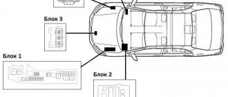
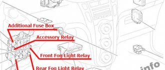
General scheme
Locations of blocks with fuses and relays
Relay description
- Radiator Fan Relay
- Range selector switch relay
- CVT relay
- Air conditioner relay
- Horn relay
- Relay for increasing idle speed
- Headlight/Front Fog Light Relay
- Rear window defroster relay
- Signal relay
- Accessory relay
- Ignition relay-1
- Ignition relay-2
- Spare fuse
- Breaker
- Fuel pump relay (under the driver's side front door trim)
- EGI relay
- Rear window wiper relay
- Rear fog lamp relay
- Ignition relay-3
- Rear fog lamp relay (depending on model)
- Radiator Fan Relay-2
* (under the dashboard on the driver's side, depending on model)
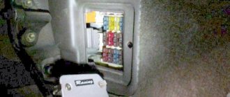
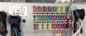
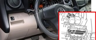
Fuses in the cabin
It is located to the right of the steering rack, covered with a protective cover. On the reverse side there will be a diagram describing the element
Option 1
| F1 | (20 A) Air conditioner-heater fan motor |
| F2 | — |
| F3 | (10A/20A) Rear window defroster switch, rear window defroster relay |
| F4 | (10A) Horn relay |
| F5 | (15A) Fog lamp relay |
| F6 | (10A) Air conditioning system, start inhibit switch |
| F7 | (7.5A) Central locking, idle speed control (ISC) relay - with automatic transmission, diagnostic connector |
| F8 | (10A) Rear window defroster relay - if equipped, central locking, central locking signal control unit, daytime running light control unit - if equipped, PVN switch, reverse lights |
| F9 | (15A) Rear window washer cleaner |
| F10 | (15A) Audio system |
| F11 | (7.5A) Hazard switch |
| F12 | (7.5A) ABS electronic control unit |
| F13 | (15A) Cigarette lighter fuse Nissan March K11 |
| F14 | (10A) Brake lights |
| F15 | (10A) Hazard switch |
| F16 | (10A) Electronic transmission control unit |
| F17 | (15A) Fuel pump relay |
| F18 | (10A) Seat heater |
| F19 | (20A) Windshield wiper motor, windshield wiper motor relay |
| F20 | (7.5A) Engine control system, immobilizer control unit |
| F21 | — |
| F22 | (10A) SRS electronic control unit |
| F23 | (10A) Windshield washer cleaner |
| F24 | (10A) Fuel cut-off valve - Diesel, interior lamps, instrument cluster, audio system, electronic transmission control unit, immobilizer, central locking signal control unit |
| F25 | (10A) Glow plug control unit - Diesel, recirculation system solenoid valve or USR - Diesel, immobilizer, heated oxygen sensor, idle air bypass control valve |
| F26 | (7.5A) Start inhibit switch relay - automatic transmission, engine management system |
| F27 | — |
| F28 | — |
| F29 | (15A) Headlight washer delay relay |
Fuse number 13 at 15A is responsible for the cigarette lighter.
Option 2
- 10A Starter
- 10A Ignition
- 10A Interior lighting
- 10A Stop lights
- 10A Signal
- 15A Fog lights
- 10A Hazard Alarm
- 10A Dimensions
- 10A Turn signals
- 10A Instrument panel
- 10A ABS
- 10A Electric power steering
- 10A Airbags
- 10A Motor
- 10A Fuel Pump
- 10A A/T Control
- 10A Air conditioner
- 15A Electric stove motor
- 10A Audio system
- 15A Cigarette lighter
- 20A Front wipers
- 10A Mirrors and rear wipers
- 15A Heated rear window
For an example of the location of the unit and replacing the cigarette lighter fuse, see the video.
This entry is purely for myself (or maybe it will be useful to someone) since I constantly lose these pictures and can’t quickly find them again. Now I will store them on my blog.
How to decipher fuses on a Toyota Mark 2: detailed instructions
Many home mechanics often have a lot of problems with Toyota Mark 2 fuses - the Japanese design solution is not always logical, as a result of which it takes car owners a lot of time and effort to replace damaged elements.
Meanwhile, there is a domestic marking of fuses on cars aimed at the European market, where each element has a sequential numbering.
If you have a car aimed at the Japanese domestic market, you will have to get a little confused - on the manufacturer’s official website you can find instructions for deciphering the hieroglyphs or symbols used on the main fuse block.
| Marking part number | Functional purpose of the element |
| 1 | The element is responsible for the operation of the engine radiator fan circuit |
| 2 | Fuse for the positive contact circuit responsible for charging the battery |
| 3 | A reserve element that is used to unload the circuit of other electrical systems or in case of connecting additional equipment not included in the package |
| 4 | An audio signal is connected through the element, and sometimes power is supplied to the central locking circuit and the additional alarm module |
| 5 | This fuse is responsible only for the operation of the right headlight. |
| 6 | This fuse is responsible only for the operation of the left headlight. |
| 7 | The module is necessary for overvoltage protection of the wheel traction control system |
| 8 | The part is responsible for the proper functioning of car de-icers - depending on the configuration, heating can be installed on the windshield and rear-view mirrors |
| 9 | Additional fuse for ignition switch circuit |
| 10 | The element is responsible for the uninterrupted operation of the 4WS system |
| 11 | The fuse is necessary to protect against overvoltage of the engine generator circuit |
| 12 | Additional fuse for engine radiator fan |
| 13 | The part is responsible for the operation of the anti-lock wheel module |
| 14 | Fuse protecting the direct injection system from power surges |
Note! If you purchase a vehicle with Japanese markings, it is recommended to replace all fuses with European adaptation by purchasing a special set of protective elements.
This step will significantly simplify the procedure for servicing the car in the future, especially if the driver sometimes turns to third-party mechanics for help - not every repairman will take on servicing Japanese electronics.
Do-it-yourself replacement of fuses on a Toyota Mark 2: everything you need to know
The procedure for replacing faulty fuses on a Toyota Mark 2, regardless of the year of manufacture of the car or its configuration, follows an identical algorithm of actions. The entire range of work will take no more than 20 minutes of free time, and you will also need the fuses themselves, a set of Phillips and slotted screwdrivers, and a specialized puller or narrow-nose pliers.
To replace fuses on a Toyota Mark 2, you must perform the following procedure:
- To begin with, be sure to de-energize the electrical circuit in the car by disconnecting all terminals from the battery;
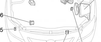
- Then, under the hood of the car, on the right side of the power unit, we find a small plastic box and use screwdrivers to remove the fixing fasteners. It is important to remember that the fuse box under the hood of the Toyota Mark 2 is sealed and damage to the fasteners may allow moisture or dust to enter the system, which in turn will lead to metal corrosion and loose contacts;
- After successfully dismantling the block cover, we conduct a visual inspection of the faulty elements. A blown fuse will have traces of melting on the body, and during dismantling it will be possible to see the destroyed part inside the product;
- Using pliers, a special puller or medical tweezers, you need to disconnect all faulty fuses and install new components. Fuses are mounted on Toyota Mark 2 by lightly pressing the part onto the connector until a characteristic click appears;
- If no faulty fuses were found, then go inside the cabin and open the second fuse box. The internal fuse box is located under a plastic cover at the bottom of the instrument panels - for free access you will have to remove the protective cover itself;
- At the end of the maintenance procedure, we connect the battery back and check all the electrical systems of the vehicle for functionality.
Note! The design of the Toyota Mark 2 electrical system sometimes causes small voltage surges when connecting or disconnecting the battery, which can damage freshly replaced fuses. In this case, the maintenance procedure will have to be repeated.
It is also recommended to pay special attention to the throughput capacity of the elements themselves - it is strictly forbidden to use fuses oriented towards higher or lower power. Using incompatible fuses or replacing fuses with protective elements and vice versa can compromise the security of the car's electrical equipment, which will lead to costly repairs in the event of a power surge or short circuit.
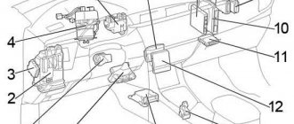
Blocks under the hood
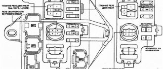
Main block
The main fuse and relay box in the engine compartment is located on the left side next to the battery.
Scheme
Designation
| COND FAN (condenser fan) | 30A |
| ALT-S (charging) | 7.5A |
| POWER №2 | 50A |
| POWER №1 | 60A |
| HEATER | 50A |
| HEAD (RH) (right headlight) | 10A |
| HEAD (LH) (right headlight) | 10A |
| TRC (traction control) | 7.5A |
| DEICER (de-icer) | 20A |
| AM2 (ignition switch circuit AM2) | 20A |
| 4WS No. 2 (4WS system) | 30A |
| ALT-S (alternator circuit) | 5A |
| 4WS No. 1 (4WS system) | 30A |
| HORN (horn) | 10A |
| MAIN (main fuse link) | 40A |
| RADFAN (radiator fan) | 30A |
| ABS (anti-lock system) | 60A |
| ALT (generator) | 100A |
| EFI (injection system) | 15A |
- CIRCUIT OPENING - fuel pump relay
- HORN - horn relay
- HEAD - headlight relay
- FAN - fan relay
- GLOW - glow plug relay
- HEATER - heater relay
- STARTER - starter relay
Fuse diagram for Cresta Chaser Mark II — Toyota Cresta, l., year on DRIVE2
When installing, refer to the assembly drawing. When installing the bushings on the stabilizer, do so as shown in the figure.
After installation, stabilize the suspension cross on the body down and lifting it up. Rear axle hub Note: Removal 1. Jack up the vehicle and remove the rear wheel. Unscrew the hub nut. Rear axle hub. Example text from the section "Steering": Installation is carried out in the reverse order of removal. When removing the pump, pay attention to the following points: After installation: Bleed the system.
Fuses and relays Toyota Mark 2 100
Remove the cylinder head cover. Remove the four nuts, spark plug tube seal, cylinder head cover and gasket.
If not, turn the crankshaft one turn? Check the valve drive clearance. Using a feeler gauge, measure the gap between the pushrod and the camshaft. Record the valve clearance measurements.
They will use the toyota cross fuse diagram to determine the required shim when replacing. Valve drive clearance cold engine: Adjust the valve drive clearance.
Rotate the crankshaft so that the lobe of the camshaft cam is at the top. Position the pusher as shown in the illustration.
Using special tool A, press the tappet, and place special tool B between the camshaft and the tappet.