Toyota Corolla E120 The E130 represents the 9th generation of the Toyota Corolla model range, which was produced in 2000, 2001, 2002, 2003, 2004, 2005, 2006 and 2007 with left and right-hand drive. Delivered all over the world (America, Europe, Asia) with various body styles. Also known as Toyota Fielder, Fielder Runx Allex (Toyota Ranks) And Toyota Corolla 124 / 130. In this publication you will find a description of the fuses and relays of the Toyota Corolla 120 (Toyota Fielder) with block diagrams and their locations. Note the cigarette lighter fuse.
The design of the blocks and the purpose of the elements in them may differ from those presented and depend on the year of manufacture, equipment level and region of delivery of your car (Right or Left hand drive). Check the purpose with your diagrams on the block cover.
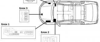
General arrangement of blocks
In total, this model has 5 main blocks with fuses and relays, and individual elements can also be installed outside them.
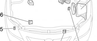
General scheme
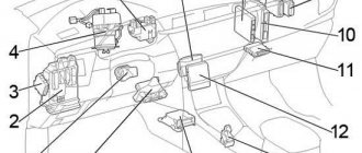
Location of blocks in the cabin for right-hand drive cars
Description
- heater relay
- mounting block under the instrument panel
- additional mounting blocks
- electric power steering control unit
- VSC system buzzer
- mounting blocks No. 7, No. 11
- turn signal switch relay
- accessory relay block
- SRS control unit
- engine and automatic transmission control unit
- control unit ABS, TRC, VSC, BA
Instructions for replacing fuses
Before replacing the fuse, it is necessary to establish the cause of the burnout of the protective element and eliminate it. As a rule, a short circuit, a break in the electrical wiring, or a power surge causes a fuse to burn out.
Fuse replacement pliers
To replace a blown fuse, specialized pliers are used. Their use allows you to grab the Toyota Corolla E120 fuse and pull it out of the seat. It is not always possible to perform this operation manually.
Replacement of fuses must be carried out in compliance with the following safety rules:
perform the operation with the battery terminals disconnected;
- in place of the blown fuse, install an element identical in rated current value;
- It is prohibited to use various jumpers to replace a failed fuse.
Blocks in the cabin
Main unit
In the general diagram it is designated as Block 2. In the cabin it is located under the panel on the left side.
Right hand drive
To gain access, you need to unscrew the screw, disconnect the fasteners and remove the glove compartment.
Example location
Photo example
Designation
Scheme
Full assignment of elements
| A | POWER 30A - electric window lifts, electric sunroof |
| b | DEFOG 30A - rear window defroster |
| With | HEATER 40A - air conditioner, heater. |
| 1 | WASH 15A - windshield wipers and washers |
| 2 | ECU-KZ 10A - ABS, electric power steering, radiator and condenser fans |
| 3 | GAUGE 10A - instrument cluster, direction indicators and hazard warning lights, seat belt and forgotten key warning systems, central locking |
| 4 | backup circuit |
| 5 | backup circuit |
| 6 | backup circuit |
| 7 | WIPER 25A – windshield wipers and washers |
| 8 | TAIL 15A - dimensions and lighting, rear fog lamp, headlight warning system, headlights |
| 9 | STOP 15A - brake lights, engine control, automatic transmission and ABS indicators |
| 10 | DOOR 25A - central locking, interior lighting, warning system, wireless central locking control |
| 11 | P/W 20A - electric window lifts |
| 12 | Reserve |
| 13 | AM1 25A - circuit AM1 ignition switch |
| 14 | ECU-B 7.5A - fog lights, engine control and automatic transmission |
| 15 | FOG 15A - front fog lights |
| 16 | ST 7.5A - instrument cluster, engine management, starting system |
| 17 | A/C 25A – air conditioning |
| 18 | IG2 15A - ABS, charging system, automatic transmission, electric power steering, engine management, ignition, SRS |
| 19 | DEF I-UP 10A - Engine management, Rear window defroster |
| 20 | Reserve |
| 21 | CIG 15A - cigarette lighter , radio, navigation system, clock, mirror adjustment |
Fuse number 21 at 15A is responsible for the cigarette lighter.
Some relays are attached to the reverse side.
Photo - diagram
Relay purpose
| A | Ignition relay |
| IN | Rear window defroster relay |
| WITH | Fuel pump relay |
| D | Electric window lift relay |
| E | Starter relay |
Left hand drive
To gain access you need to remove the glove box.
Example of assignment from the glove box lid
Scheme
Description
| 1 | not used |
| 2 | not used |
| 3 | not used |
| 4 | 25A FUEL HTR - Fuel heater |
| 5 | 15A CIG - Cigarette lighter , audio system, clock, controls for electric rear-view mirrors |
| 6 | 15A IG2 - Sensors and counters, SRS air bag system, multi-channel fuel injection system/sequential multi-channel fuel injection system, starter system, charging system |
| 7 | 10A M-НТR/ DEF I-UP — Anti-fog of external rear-view mirrors, multi-channel fuel injection system/ sequential multi-channel fuel injection system |
| 8 | 7.5A ST - Starter, multi-channel fuel injection system/sequential multi-channel fuel injection system, sensors and counters |
| 9 | 10A ECU-B - Air conditioning system, anti-lock brake system, vehicle stability control system, rear fog lamp |
| 10 | 25A AM1 – Fuse “CIG” |
| 11 | 15A TAIL - Dimensions, Taillights, License Plate Lights, Parking Lights, Headlight Beam Control, Instrument Panel Lights, Clock, Headlight Cleaner, Front Fog Lights, Seat Heaters, Multiport Fuel Injection System/Sequential Multiport Injection System fuel |
| 12 | 20A P/V – Electric drive window |
| 13 | 15A STOR - Brake lights, high mounted brake light, gear lock control system, multi-channel fuel injection system/sequential multi-channel fuel injection system, anti-lock brake system, vehicle stability control system |
| 14 | 15A FOG - Front fog lights |
| 15 | 25A DOOR — Electric door locking system |
| 16 | not used |
| 17 | 10A A/C - Air conditioning system |
| 18 | 7.5A OVD - On-board diagnostic system |
| 19 | 10A GAUGE - Gauges and meters, air conditioning system, power windows, reverse signals, daytime running lights, rear window defogger, automatic transmission overdrive system, power door locking system, charging system, hazard warning lights, automatic anti-glare interior rearview mirror, SRS airbag system, front passenger seat belt indicator light |
| 20 | 15A S-НТR — Seat heaters |
| 21 | 15A WASH - Windshield wipers and windshield washer |
| 22 | 10A ECU-IG - SRS air bag system, electric cooling fan, anti-lock brake system, gear lock control system, electric steering system, headlight cleaner |
| 23 | 25A WIPER - Windshield wipers and windshield washer, windshield wipers and rear window washer |
| 24 | 40A DEFOG — Rear window anti-fog, fuse “M-HTR/DEF I-UP” |
| 25 | 30A POWER - Electric drive window, electric sunroof |
| 26 | 40A HEATER - Air conditioning system, fuse "A/C" |
Relay diagram on the back of the block
Designation
| A | Ignition relay |
| B | Rear window defroster relay |
| C | Fuel pump relay |
| D | Electric window lift relay |
| E | Starter relay |
| F | Electric window lifts, electric sunroof |
| G | Rear window defroster, air conditioning, heater |
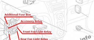
Additional relay block
In the general diagram it is designated as Block 5 In the cabin, located under the panel on the right side.
Scheme
Purpose
| A | Idle speed control system relay |
| B | Fog light relay |
| C | Relay for accessories |
| D | Heater relay |
Signs of breakdown
As mentioned above, the car has special elements that protect all electrical appliances in it from short circuits. If a short circuit or interruption occurs in the electrical circuit, the current begins to increase, and in order to protect the wires from fire, the thread located in the fuse burns out.
Each fusible element has its own designation; this is done so that you can quickly find and replace a burnt-out element. Thanks to the knife-shaped contacts, they can be easily removed from their seat for replacement. You can replace them yourself without any special equipment. You can understand that it has failed by the condition of the connecting wire, which is visible thanks to the transparent plastic case, but it also happens that the integrity of the case is compromised, as a result of which it fails.
They differ from each other in their design, and in case of burnout they have their own characteristics.
There are three types of fuses installed on Toyota Corolla;
- View A, the state of the thread can only be understood when removed;
- View B, you can check its integrity without removing it;
- View C, just like in the second case, you can understand what state the thread is in without removing it, the only difference is in the form of a fusible insert.
They differ from each other in their design, and in case of burnout they have their own characteristics.
Important: If any electronic device in the car stops working, the first thing you need to check is the condition of the fuses.
Blocks under the hood
Mounting block
In the general diagram it is designated as Block 1. It is located on the left side, next to the battery.
Example of a circuit from a block cover
Scheme
Decoding
| A | Electric power steering relay |
| IN | Air conditioning compressor clutch e/m relay |
| WITH | Horn relay |
| D | Injection relay |
| E | Radiator fan relay #2 |
| F | Radiator fan relay #1 |
| A | EMPS (50A) - electric power steering |
| b | HEAD MAIN (40A) - headlights |
| With | A/PUMP (50A) - engine control (2ZZ-GE) |
| d | ALT (100A) - charging system, rear window defroster |
| e | H-LP CLN (30A) – headlight washer |
| f | RDI FAN (30A) - radiator and condenser fans |
| g | ABS No. 1 (30A) or VSC No. 1 (40A) - ABS |
| h | ABS No. 2 (40A) or VSC No. 2 (40A) - ABS |
| 1 | HEAD RH (15A) - right headlight |
| 2 | HEAD LH (15A) - left headlight |
| 3 | HORN (10A) - sound signal |
| 4 | HAZARD (10A) - direction indicators and hazard warning lights |
| 5 | ALT-S (5A) - charging system |
| b | spare |
| 7 | EFI (15A) - engine control, automatic transmission operating mode indicators, headlights, interior lighting, automatic air conditioning, radio, headlights warning system, remote control central locking, ABS (VSC) |
| 8 | DOME (15A) - clock, instrument cluster, headlights, interior lighting, air conditioning with automatic control, radio, warning system, lights not turned off, remote control |
| 9 | AM2 (30A) - circuit AM2 ignition switch |
| 10 | backup circuit |
| 11 | backup circuit |
| 12 | backup circuit |
| 12 | backup circuit |
Block 3
Installed next to radiators and cooling fans.
Scheme
Description
- Radiator fan relay #1
- Radiator fan relay #2
- Radiator fan relay #3
Toyota Corolla 120 (124/130) body (Fielder) fuses and relays
Toyota Corolla E120 E130 represents the 9th generation of the Toyota Corolla model range, which was produced in 2000, 2001, 2002, 2003, 2004, 2005, 2006 and 2007 with left- and right-hand drive. Delivered all over the world (America, Europe, Asia) with various body styles. Also known as Toyota Fielder and Toyota Corolla 124/130 . In this publication you will find a description of the fuses and relays of the Toyota Corolla 120 (Toyota Fielder) with block diagrams and their locations. Note the cigarette lighter fuse.
The design of the blocks and the purpose of the elements in them may differ from those presented and depend on the year of manufacture, equipment level and region of delivery of your car (Right or Left hand drive). Check the purpose with your diagrams on the block cover.
Where is?
Toyota Corolla fuses are located in mounting blocks. But in this model there is not one block, but several, and accordingly, the circuits for them will be different. One of the power supplies is located in the vehicle interior, the second is in the engine compartment. For greater clarity, check out the power supply diagrams installed in the cabin and under the hood.
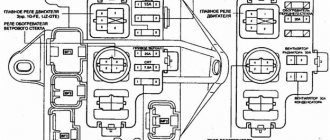
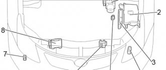
PSU in the engine compartment
To see this fuse box, you will need to gain access to the engine compartment. It is located on the right side when facing the hood. On the side of the fender liner, opposite the driver's seat, you can see a plastic cover behind which the device itself is hidden. Having opened the cover, a diagram of the elements is printed on its reverse side. Also, a diagram of the device components is shown below.
PSU diagram under the hood with digital designations of the device elements
The numbers above indicate all components of the Toyota Corolla fuse box. To make it more clear to you what they are responsible for, check out their designations below.
Designation table for power supply chain links under the hood
Designation table for power supply chain links under the hood
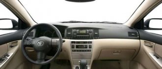
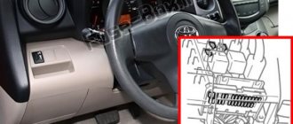
PSU in the cabin
As for the interior device, it is located, as you might guess, in the interior of your Toyota Corolla. In particular, it is located on the left side, if you sit in the driver's seat, under the dashboard. To get to it, you must open the plastic protective cover of the device. Here there are both relays and fuses themselves, the diagram of which is shown below.
Scheme of digital designations of relays and fusible elements of the electrical circuit located inside the vehicle
If everything is clear with the block diagram, then let’s move on to the notations given below.
Designation table for power supply chain links in the elephant of the machine
Designation table for power supply chain links in the elephant of the machine
Toyota Corolla › Logbook › Starter unloading relay
As I already said, I had problems with the factory starting hot. I could drive by stopping at a gas station or a store, turning off the engine and sitting in the car while trying to turn the starter for 10 minutes to an hour and a half in hot weather. No matter what I was guilty of, but based on the symptoms, the loss of power when trying to start was more appropriate. We turn the key to start - as a result there is silence. I decided to start with the reluhi. I went and bought: a 30 ampere relay, a mother for the relay, ring lugs, mother and father connectors, 2 wires of 2.5mm section per meter white and red and 2 meters of 2.5mm section black, 2 meters of corrugations and started sawing :))) At first I just I drilled my closet with a screwdriver :D, because I couldn’t gather my thoughts into a fist, but after 5 minutes and 15 holes in the closet, I got to work