Operating a vehicle with low or high tire pressure not only has a bad effect on dynamic performance and fuel consumption, but is also accompanied by a significant deterioration in the vehicle’s handling and safety. Therefore, the Toyota RAV4 has special sensors that control the degree of wheel inflation.
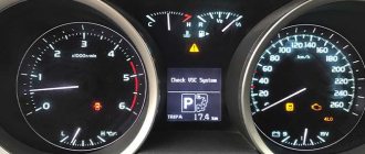
When the pressure deviates from the norm, the indicator on the instrument panel lights up. The driver is promptly informed about problems with the wheels, which allows appropriate measures to be taken in time.
Cost and part number for tire pressure sensors for Toyota RAV4
Toyota RAV 4 uses original tire pressure sensors with article numbers 4260730040, 42607-30071, 4260742021, 42607-02031, 4260750011, 4260750010. Their price ranges from 2800 to 5500 rubles. In addition to branded meters, there are analogues from third-party manufacturers. The table below shows the best brands whose sensors perform well on vehicles.
Table - Toyota RAV4 tire pressure sensors
| Firm | Catalog number | Approximate cost, ruble |
| General Motors | 13348393 | 2400-3600 |
| VDO | S180211003Z | 1700-2000 |
| Mobiletron | TXS066 | 1200-2000 |
Automated binding
The sensors are paired automatically during the test drive. 1. Install the sensor on the car. 2. Inflate all tires to the pressure recommended by the vehicle manufacturer. 3. To bind the sensors to the car, it is necessary to carry out a test drive at a speed of at least 40 km/h for up to 20 minutes. If the sensor in the spare wheel has been replaced, then its binding to the car is carried out using diagnostic equipment, by entering the sensor identifier into the vehicle's on-board complex (on some cars, the spare wheel sensor is linked automatically). For some cars, before a test drive, the manufacturer recommends leaving the car with the ignition on for 15-20 minutes without moving to recognize the new sensors. This requirement is desirable, but not required.
Sensor device in Toyota Rav4 tires
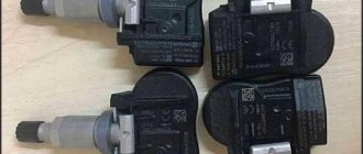
To begin with, it is worth noting that the original units have catalog number 42607-30071, are produced under the Pacific brand and are quite expensive. Moreover, the warranty on new spare parts is 12 months. The best analogue, according to experts, is Shnaider; it is more affordable in price and has a 24-month warranty. As for the device, it is the same for all options:
- a housing within which all components are arranged;
- air valve with rubber outer part assembled with nipple;
- nut for fixing on the outside of the disk;
- protective cap;
- fasteners - connecting screw, gaskets and washers;
- an electronic board that transmits a signal at a certain frequency;
- battery to ensure autonomous operation.
By the way!
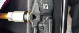
The sensors have a characteristic appearance - a metal nipple, which is visible from the outside, and a wide plastic body with an oval end on one side and a rectangular end on the other.
What to do if the tire pressure light comes on
If the light indicating low tire pressure is on, this does not always indicate a problem. False alarms often occur due to poor road surfaces or changes in temperature. Despite this, when a signal appears, it is prohibited to ignore it. It is important to inspect the wheels for damage. You also need to check the tire pressure. If it is below normal, then the wheels should be inflated using a pump.
A problem with the pressure sensor can be identified by visually inspecting it. Often on Toyota RAV 4 there is a mechanical breakdown of the housing and meter mount. In this case, it is not necessary to remove the tire from the rim to check. It is enough to rotate the wheel and listen to the sound coming from it.
Reading the error log also allows you to discover the reason for the low pressure indicator to light up. Based on the data received, troubleshooting actions must be taken.
Vehicle Tire Pressure Monitoring System (TPMS) Protocol Study
Tire Pressure Remote Monitoring System (TPMS )
— Tire Pressure Monitoring System) is designed to promptly inform the user about a decrease in tire pressure and the critical temperature of the tires. Sensors are available in internal or external versions. The internal ones are installed inside the tire of a tubeless wheel, the external ones are screwed onto the wheel fitting. A wheel with an internal sensor is completely identical in appearance to a wheel without a sensor. Such a wheel is easy to inflate. The external sensor is noticeable, it can be stolen, and when inflating the wheel, it must first be unscrewed. It is also exposed to atmospheric phenomena.
I was prompted to study the operating protocol of the TPMS system by the idea of installing such a system on a baby stroller for operational monitoring of tire pressure.
Fig.1. Appearance of the TPMS system
Fig.2.
TPMS system controller board It was not possible to simply install a standard receiving unit, since its minimum permissible pressure value is 1.1 Bar, and in a stroller it is less. Therefore, the module constantly beeps, informing about low tire pressure. You can read about the development of a controller for the “Smart” baby stroller “Maximka”, in which the research results were applied, in my article [1].
I started collecting information about the work of TPMS by searching for articles on the Internet. But, unfortunately, there is little information. Yes, and it usually concerns standard car systems, which are a little more complicated and much more expensive. But I needed information about a simple Chinese cheap system. I had some minimal understanding, now I had to start experimenting.
So, we arm ourselves with the USB whistle of the DVB tuner, launch RTL-SDR and watch the broadcast. The sensors operate at a frequency of 433.92 MHz in FSK modulation. Initially, I recorded the broadcast and then manually parsed the protocol. This is where the difficulties began. Previously I only encountered OOK modulation. Everything is simple there. It's a little more complicated here. Information is encoded at two frequencies. Therefore, I studied examples and theory on modulations. Then I saw how the URH-Universal Radio Hacker program was used [2, 3]. I tried to install it, but it doesn’t work on my WinXP 32bit. I had to look for a computer with win8 64bit and then the program was installed. You can read more about its work on the developer’s website. URH made the process easier for me in some ways, because... it captures a signal from the air, displays it as an oscillogram and immediately decodes it into raw digital form in both binary and hex form.
Fig.3. Screenshot of a program with a captured frame of a TPMS message
The sensor sends several parcels one after another in one session. The period between sessions can reach a minute or even more. If an alarming situation occurs, the sensor immediately begins sending data packets. Sound file of the message from the sensor [8]. An example of one message from a sensor taken from the URH program:
010101010101010101010101010101010101010101010101010101010101010101010101010101010101010101010101010101010101010101010101010 1010101010101010101010101010101010101010101010101010101010101010101010101010101010101010101010101010101010101010101010101010101 01010101010101010101010101010110011001101001101010010110010110100110101001101010011001010101010110100101010101010101101010010 11001101010010101100101101001010101011001011001100110101001 In hexadecimal form, this premise will take the form: 5555555555555555555555555555555555555555555555555555 5555555555555556669a965a6a6a6555a5555a966a565a556599a9 It was clear that all 4 parcels in one session had the same data, which means the packet was received correctly and we can begin to analyze it.
In the example above you can see the preamble (sequence 01010101....), then comes the data. After reading the Internet, we understand that this is a parcel encoded with Manchester encoding (GE Thomas). Each bit is encoded by two bits 01 or 10. I initially encoded by hand, thereby reinforcing the encoding/decoding theory. But then I decided to turn to an online decoder [4,5,6], which greatly speeded up the process.
So, having decoded the original message from the sensor using the Manchester code, we get
000000000000000000000000000000000000000000000000000000000000000000000000000000000000000000000000000000000000000000000000000000000000000000000000000000000000000000000000000000000000 000000000000000010101101110010011011101110100000011000000001110010111000100110000010010101110 The first 136 zeros are a preamble, it can be discarded. We are only interested in data.
Converting them to hexadecimal form, we get: 0x15B937740C03971304AE
This already has beautiful initial data, which somewhere contains an identifier, tire pressure and temperature.
For further research it is necessary to collect data statistics. To do this, I screwed one sensor to the wheel and captured the air, while simultaneously recording what the original system display showed. I released the pressure, pumped it up, put the wheel in the freezer for a negative temperature, and heated it up. Then I achieved the same conditions for another sensor to find out the temperature and pressure bytes.
The entire package takes 10 bytes. If you arrange the received decoded data in a column, you can see constant data and changing data.
15B937740C03971304AE 15B937740C03A1FC00A4 15B937740C03A700087B The sensors have stickers on the housing. Each sensor has a different one: 0A, 1B, 2C, 3D.
Stereotypical thinking did not help here. I thought that this was the ID sensor. I doubted why the ID took up only 1 byte, but then I forgot about it and tried to look for these identifiers in the stream. Then in the menu of the original system receiver I saw that other sensors can be linked to this receiver, and the receiver itself shows the sensor identifier on each wheel. And, lo and behold, I discovered that the fourth wheel sensor has ID = 3774.
15B937740C03971304AE This means that the 3rd and 4th bytes of the parcel are the wheel identifier. I compared it with other sensors and the identifiers also coincided with those displayed by the standard panel.
I counted the 1st byte as the prefix of the beginning of the data, and the 2nd byte as the identifier of the TPMS subsystem. Below I have provided parcels from different sensors for comparison.
15B9F3FA2300BE1B007B Sensor 0A ID=0xF3FA 15B91AA43201B71B002A Sensor 1B ID=0x1AA4 15B9ABFF32027B1B029B Sensor 2C ID=0xABFF 15B937740C03971304AE Sensor 3D ID =0x3774
And I realized that the inscriptions on the sensors (0A, 1B, 2C, 3D) are just wheel numbering in digital and alphabetic form, and not a hexadecimal wheel identifier. But, nevertheless, the 6th byte in the parcel is very similar to the serial number of the sensor. I concluded for myself that this is the wheel identifier. This means that one more byte has been decoded.
The last byte is most likely a checksum, which I don’t know how to calculate yet. This remained a mystery to me until the very end.
The next byte decoded is the wheel temperature. Lucky here. The temperature takes 1 byte and is presented in whole degrees. Negative temperature in additional code. This means that a temperature of -127…128 degrees Celsius will fit into a byte.
In our package, temperature is the 8th byte
15B9F3FA2300BE1B007B 0x1B corresponds to +27 degrees 15B937740C03A1FC00A4 0xFC corresponds to -4 degrees
There are three unrecognized bytes left: 5th, 7th, 9th. Judging by the dynamics of changes in tire pressure, the tire pressure is hidden in 7 bytes, and in the 9th byte, most likely, the status bits of the sensor. According to various sources of information on the Internet, as well as the functionality of my TPMS system, there should be a low battery bit, a rapid pressure loss bit, and a couple more bits that are not clear for what.
So, we will analyze the 7th byte, because we mean that the pressure is hidden in it. Having collected statistics on different sensors with different pressures, I could not clearly determine the formula that recalculates the pressure. And it is not clear in what default units the sensor transmits pressure (Bar, PSI). As a result, the table built in Excel did not provide an exact match with the standard TPMS display. One could neglect this difference of 0.1 Bar, but I wanted the concept of a protocol down to the last bit. The excitement took over.
If you can’t understand how the pressure byte is generated, then you need to make an emulator of the pressure sensor and, changing the pressure value, see what the standard panel displays.
It remains to find out the purpose of the 5th and 9th bytes of the packet, but they rarely change, so you can take their values as in the original packet, changing only the pressure byte. Now the only question is calculating the checksum. Without it, the standard panel will ignore my package and show nothing.
To emulate the sensor, it was necessary to transmit a packet. To do this, I had an SI4432 transceiver connected to a PIC16F88, once used for other purposes.
Fig.4. Photo of the test board
Taking advantage of old data transfer practices, I sketched out a program for PIC that transmits one of the packets that I received from the URH program. Some time after turning on the transmitter, the panel displayed the data that was transmitted to it! But this is a ready-made package with a ready-made CRC, and in order for me to change the pressure byte, I also need to recalculate the CRC.
I started reading, looking for information about what CRCs are used, tried different Xor, And, etc., but nothing worked. I already thought that nothing would work out and that I would have to be content with the pressure that I received according to my table, but it did not coincide a little with the original scoreboard. But on the Internet I saw an article about the selection of CRC. There was a program to which you give several packets, and it tries to find a checksum and, if successful, produces the value of the polynomial and the CRC initialization value. [7]
We specify several packages for the program:
reveng -w 8 -s 15B9ABFF3202AA1B0017 15B9ABFF3202AA1B0249 15B9F3FA2300D01A00D8 15B937740C037B130089 15B937740C03BD18025E 15B9ABFF32028F150834 The program produces: width=8 poly=0x2f init=0x43 refin=false refout=false xorout=0x00 check=0x0c residue=0x00 name=(none) I wrote a program for calculating CRC taking into account this data and ran it through the packages that I received earlier - everything came together! // I consider the CRC for this crc=0x43; // Initial value for correct calculation for(j=0;j<9;j++) { crc ^= tmp[j]; for(i=0;i<8;i++) crc=crc&0x80 ? (crc<<1)^0x2F : crc<<1; // Polynomial 0x2F to calculate the correct CRC } My hands were itching to broadcast pressure data. Having supplemented the test program with CRC calculations, I transmitted the first packet. The standard panel received the signal and displayed pressure and temperature. A small problem was that the standard panel had one decimal place and, when transmitting the value on the air, the same pressure was always displayed on the screen, because the remaining digits were invisible. Transmitted byte value 0..255. But again it’s somehow not clear. It turned out that the pressure of 0.00 Bar begins when the 7th byte contains the value 97. It is not clear why this is so. But then, with a discreteness of 0.01 Bar, everything is clear.
Byte P Pressure, Bar 255 1.58 254 1.57 … … 107 0.10 106 0.09 105 0.08 104 0.07 103 0.06 102 0.05 101 0.04 100 0.03 99 0, 02 98 0.01 97 0.00
Judging by the table, the maximum pressure that fits in one byte is only 1.58 Bar, but the system allows you to measure pressure up to 4 Atm. This means that 1 bit of the most significant bit is hidden somewhere else. There was no desire to go through all the bytes and change the bits in them. A car wheel was found, a sensor was screwed onto it, and the signal was captured. Curiosity got the better of me and I made mental bets on where this bit would appear. And that it will be exactly one bit, and not some other encoding scheme.
After decoding the packet, I saw this bit. It is the 7th bit of the 6th byte. This means that the 6th byte contains not only the wheel number, but also the most significant bit of the tire pressure. 15B937740C833C18025C
The most significant bit from 0x83 and 0x3C gives 0x13C = 219 which corresponds to a pressure of 2.19 Bar Formula for converting pressure to Bar: P=(ADC-97)/100, Where ADC = (B7>>7)*0x100+B6, where B6 and B7 is the value of byte 6 and byte 7.
With a value of 511 we have a maximum pressure of 4.14 Bar. It was also not clear why the bar is 4.14 Bar, but I guess that this is equal to 4 Atm - the maximum permissible pressure for the sensor.
It remains to understand what the status bits are responsible for. By releasing the pressure, connecting the sensor to a regulated power supply and reducing the voltage, the bits were obtained. 2 bits remained unclear. There may be more, but they never took the value of one during all the experiments.
To simplify the analysis, a program was written [8]
Fig.5. Appearance of the program interface for studying TPMS packages
The program can be given a raw packet from the URH program in hexadecimal form and the program decodes the packet, calculates the checksum and displays the data in normal units of temperature and pressure.
Somehow I went back to the standard panel menu and saw that the sensor identifier was not two bytes, but four. The panel has large and small indicators and I did not immediately notice that the 2nd and 5th bytes are also included in the sensor identifier.
15B937740C833C18025C
Thus, only the 1st byte remains unrecognized, but it is always 0x15 (0b010101), and this looks like some kind of packet preamble or identifier of its beginning.
Also, the status bits are not accurately recognized, but there are enough of those that exist.
Curiosity to find out what was inside the sensor took over and I disassembled one of them (Fig. 6)
Fig.6. TPMS sensor
It is based on an Infineon SP372 chip with a small trim. A search for documentation for this particular microcircuit yielded nothing. The ones I found were either review or advertising. So it was not possible to find out about the protocol. But the articles mention that this is a programmable controller, so the program can be anything. Therefore, I did not risk buying the microcircuit separately.
Protocol
Now about receiving data from the sensor to the SI4432 transceiver.
The original plan was to receive raw data from the SI4432 so that the controller would decode Manchester and collect the bytes. But this transceiver has a packet processing function. That is, for transmission, you can set the transmitter to the desired frequency, modulation, deviation, set the preamble length, encoding, sync word, bit rate, data length. Then write the original data packet into the transmitter buffer (for example, our 15B937740C833C18025C) and start the transmission. The transceiver itself will generate a packet and broadcast it, observing all the specified parameters, and the controller at this time is free to process other information. Ideally, I wanted to get batch processing of data from the SI4432 when receiving. For the receiver to receive the packet and generate an interrupt indicating that the packet has been received. Then the controller simply reads the receive buffer, which already stores data in its pure form, thereby freeing up processor time for other functions.
I began to study setting up registers for the reception transceiver. This turned out to be much more difficult than transmitting the package. Here you need to know well the theory of radio reception, which I don’t have. There are register calculation tables in Excel for this transceiver, but they either do not work due to the fact that Excel is Russian, or they are truncated. There is also an application from the developer, but everything there is also not very transparent. After going through many examples and looking at calculation tables, I manually calculated the register values according to the documentation.
I connected a logger to the receiver output and captured the air, looking at what the receiver outputs. As a result, I managed to configure the receiver filters so that it would let my packet through. He manipulated the speed of the flow, beat the tambourine. The theory, unfortunately, is still not clear to me.
In order for the receiver to receive a data packet, it must indicate the length of the preamble, the sync word, which must be present, and the length of the data. It is also possible for the receiver to calculate the checksum itself, but in the SI4432 the calculation algorithm does not correspond to the CRC algorithm of pressure sensors.
The mandatory presence of a two-byte sync word could have clouded the idea of receiving the packet, but it was lucky that the message from the sensor starts at 0x15B9 (15B937740C833C18025C) and is the same for all sensors. This means that 0x15B9 was set for the sync word. The data packet length is 8 bytes, checksum analysis is disabled. We set the interrupt to be generated when a packet is received and start the reception procedure.
When the receiver receives the preamble, sync word 0x15B9 and 8 bytes of data, it will issue an interrupt to the main controller, which simply reads 8 bytes of data from the receiver buffer. Next, the main controller will calculate the checksum, compare it and decode the received data. Fortunately, everything worked out as planned!
Fig.7. Photo of the standard TPMS indicator and smart stroller display
Below is an example of initializing the SI4432 transceiver for reception:
WriteSI4432(0x06, 0x05); // interrupt all disable WriteSI4432(0x07, 0x01); // to ready mode WriteSI4432(0x09, 0x7f); // cap = 12.5pf WriteSI4432(0x0A, 0x06); // uC CLK: 1 MHz WriteSI4432(0x73, 0x00); // no frequency offset WriteSI4432(0x74, 0x00); // no frequency offset WriteSI4432(0x75, 0x53); // 430-440MHz range WriteSI4432(0x76, 0x62); // 0x621A-433.924 kHz WriteSI4432(0x77, 0x1A); // low part WriteSI4432(0x79, 0x00); // no frequency hopping WriteSI4432(0x7a, 0x00); // no frequency hopping // Configuring receiver registers for speed 9090/2 WriteSI4432(0x1C, 0x81); // 01 IF Filter Bandwidth register WriteSI4432(0x1D, 0x44); // 44 AFC Loop Gearshift Override register WriteSI4432(0x1E, 0x0A); // 0A AFC Timing Control WriteSI4432(0x1F, 0x05); // 00 Clock Recovery Gearshift Override WriteSI4432(0x20, 0x28); // 64 Clock Recovery Oversampling Ratio register WriteSI4432(0x21, 0xA0); // 01 Clock Recovery Offset 2 register WriteSI4432(0x22, 0x18); // 47 Clock Recovery Offset 1 register WriteSI4432(0x23, 0xD2); // AE Clock Recovery Offset 0 register WriteSI4432(0x24, 0x08); // 12 Clock Recovery Timing Loop Gain 1 register WriteSI4432(0x25, 0x19); // 8F Clock Recovery Timing Loop Gain 0 register WriteSI4432(0x2A, 0x00); // 00 AFC Limiter register WriteSI4432(0x69, 0x60); // 60 AGC Override 1 WriteSI4432(0x70, 0x26); // Manchester encoding, data in inversion WriteSI4432(0x71, 0x22); // FSK modulation, FIFO WriteSI4432(0x72, 31); // Deviation 31*625=19375 Hz (you can try to remove it in receive mode) WriteSI4432(0x34,10); // 10 — preamble length in 4-bit nibbles WriteSI4432(0x35.0x1A); // preambula threshold WriteSI4432(0x36,0x15); // Sync word 3 is 0x15 WriteSI4432(0x37.0xB9); // Sync word 2 is 0xB9 WriteSI4432(0x27.0x2C); // RSSI // Header settings WriteSI4432(0x33, 0x0A); // fixpklen=1, Synchronization Word 3 and 2 WriteSI4432(0x32, 0x00); // Disable header filtering WriteSI4432(0x30, 0x80); // Skip2ph, Enable Packet RX Handling=0 (you can try removing Skip2ph...) WriteSI4432(0x3E, 0x08); // Received data length is 8 bytes WriteSI4432(0x0B, 0x12); // setting GPIO0 to enable TX transfer mode WriteSI4432(0x0C, 0x15); // configure GPIO1 to enable RX receive mode // Reset FIFO TX WriteSI4432(0x08, 0x01);//write 0x01 to Operating Function Control 2 register WriteSI4432(0x08, 0x00);//write 0x00 to Operating Function Control 2 register // Reset FIFO RX WriteSI4432(0x08, 0x02);//write 0x02 to Operating Function Control 2 register WriteSI4432(0x08, 0x00);//write 0x00 to Operating Function Control 2 register //Disable all interrupts except: Receive preamble, Receive sync word, Receive packet WriteSI4432(0x05, 0x02); // Interrupt when receiving a packet WriteSI4432(0x06, 0x00); //Reading interrupt status registers to clear current interrupts and reset NIRQ to log. 1 SI4432_stat[0] = ReadSI4432(0x03); SI4432_stat[1] = ReadSI4432(0x04); WriteSI4432(0x07, 0x05); // Turn on RECEIVING the air The data reception itself will look like this: if (si_int) // If an interrupt has arrived from the receiver SI4432 { //reading status registers to clear interrupt flags SI4432_stat[0] = ReadSI4432(0x03); SI4432_stat[1] = ReadSI4432(0x04); SI4432_RSSI = ReadSI4432(0x26); if (SI4432_stat[0]&0x02) { WriteSI4432(0x07, 0x01); // I complete the reception. Thus, you can continue later. If you do not complete, then the packets will no longer be accepted SI4432_ReadFIFO(); // Read 8 received bytes from the FIFO TPMS_Parsing(); // Check CRC and parse data // Reset FIFO WriteSI4432(0x08, 0x02); // write 0x02 to Operating Function Control 2 register WriteSI4432(0x08, 0x00); // write 0x00 to Operating Function Control register 2 //WriteSI4432(0x07, 0x05); // Enable RECEIVING ether } else { // Reset FIFO TX WriteSI4432(0x08, 0x01);//write 0x01 to Operating Function Control 2 register WriteSI4432(0x08, 0x00);//write 0x00 to Operating Function Control 2 register // Reset FIFO RX WriteSI4432(0x08, 0x02);//write 0x02 to Operating Function Control register 2 WriteSI4432(0x08, 0x00);//write 0x00 to Operating Function Control register 2 } if (SI4432_stat[0]&0x80) { // Reset FIFO RX WriteSI4432(0x08, 0x02);//write 0x02 to Operating Function Control 2 register WriteSI4432(0x08, 0x00);//write 0x00 to Operating Function Control 2 register } WriteSI4432(0x07, 0x05); // Enable RECEIVING ether si_int=0; } The SI4432_ReadFIFO() function simply reads 8 bytes from the receiver buffer, which contain the data from the sensor.
The TPMS_Parsing() function parses the checksum and decodes the information into final units of pressure and temperature, as well as status information.
Problems
- While reading information about sensors, synchronization of sensors with each other was mentioned. For some reason it is necessary to pair the sensors, there was something about a speed of more than 20 km/h for 30 minutes. It is not clear why this is necessary. This may be due to the timing of the information transfer, but this is my guess.
- I haven’t fully figured out the functions of the pressure sensor status bits.
- It is not clear about setting up the SI4432 transceiver for reception, or about the transmission speed using Manchester encoding. It works for me, but I don’t understand the principle yet.
Results of work
The research covered in this article took about a month of free time.
As a result of the work on studying the protocol for the operation of the tire pressure monitoring system, issues of transmitting and receiving data over the air were raised, signal encoding was briefly considered, and the SI4432 transceiver was tested for transmission and reception. This task made it possible to integrate TPMS into the main project of a “smart” stroller. Knowing the exchange protocol, you can connect more sensors and integrate them into your development. Moreover, the controlled pressure can be within a wide range, and not as in the standard system 1.1-3.2 Bar, because pressure outside this range is accompanied by an alarming squeak from the system of the standard central unit. TPMS can also now be used to monitor tire pressure on a motorcycle, bicycle or, for example, an air mattress. All that remains is to physically install the sensor and write a top-level program.
Links
- “Smart” baby stroller “Maximka”
- github.com/jopohl/urh
- www.rapidtables.com/convert/number/hex-to-binary.html
- www.rapidtables.com/convert/number/binary-to-hex.html
- eleif.net/manchester.html
- hackaday.com/2019/06/27/reverse-engineering-cyclic-redundancy-codes
- My utilities, sample package, CRC selection. Archive password "tPmSutiLity" dropmefiles.com/MtS9W"
- i56578-swl.blogspot.com/2017/08/eavesdropping-wheels-close-look-at-tpms.html
- www.rtl-sdr.com/tag/tpms
How to reset
If the air pressure in the tires is normal, but the icon on the display continues to light, then there are 4 methods to reset the Toyota Rav 4 tire pressure sensor:
- Option without reboot. Keeping a speed of 60-70 km/h, drive 15-17 km. Then stop and turn off the engine. The next time you start, the problem should disappear.
- Reboot TMPS. You need to turn on the ignition, but do not start the car. Press the SET button under the steering wheel. Hold it until the indicator blinks 3 times. Turn off the ignition, wait 2-3 minutes. Then turn on the motor. The icon should disappear.
- If the problem persists after restarting, it is worth deflating and then inflating all tires. To update data from the sensors, you need to drive 5-6 km at a constant speed of 30 km/h.
- If a failure occurs in the on-board computer, then it can also be rebooted. First, use a wrench to disconnect the negative terminal from the battery. Then you should, without turning on the engine, turn the ignition and press the horn for a few seconds. Now the terminal can be connected in place.
If all methods have been tried and the light is still on, then you should contact a car service center. Perhaps an error has crept into the system's operation or one of the tires has been damaged.
Other problems
Sometimes the tire pressure light will turn on again and this indicates a bigger problem. Here's what it might mean:
- One of the tires may be leaking air slowly
- The system may have an internal fault that prevents it from functioning properly
- Wheel sensor requires replacement (in indirect/indirect tire pressure management system)
In an indirect tire pressure monitoring system, if the sensor fails, the ABS warning light also comes on. In each case, this means that the vehicle must be diagnosed at a technical center, where an auto mechanic can detect the problem and fix it. The service will also help you repair or replace a faulty tire pressure monitoring system component.
For reference:
Indirect tire pressure monitoring system
The sensors do not measure tire pressure, but their rotation speed and the distance traveled per wheel rotation. If the tire is flat or the pressure in the wheel begins to decrease, over a certain distance the wheel will make more revolutions, since the lower the pressure in the wheel, the smaller its diameter.
The indirect (indirect) tire pressure monitoring system determines how far the car has traveled per full wheel rotation. If the standard data does not comply, the system warns the driver of a possible problem with the wheel. Unfortunately, in this case the driver has no information about which wheel is likely to have a problem.
Direct tire pressure monitoring system
This tire pressure monitoring system uses sensors on the wheels to monitor the pressure in each wheel. By collecting data on pressure and its changes , the sensors transmit information to the car’s computer, which, analyzing the information received, if necessary, signals the driver about a problem in the wheel or wheels.
Disconnect and reconnect your car battery
Your car has an on-board computer that checks all the sensors in the car (such as tire pressure monitoring system sensors) and decides what to do with that information. Just like your computer at home, sometimes electronics can experience system glitches. The fastest and easiest way to solve the problem of a computer crash is to restart it. Unfortunately, in order to reboot the computer in your car, you will have to first disconnect it from the power supply. To do this, you will need to briefly disconnect the negative (-) terminal of your car's battery.
First, open the hood of your car. Locate the battery and disconnect the negative cable from the battery. To do this you will need a wrench. After this, get into the car, turn on the ignition without starting the engine, and press the horn for about three seconds. This will drain any remaining energy stored in the vehicle's electrical system. Next, connect the negative cable back to the battery.