Before replacing the oxygen sensor, you need to make sure that it is this that is causing the engine to malfunction: failures during acceleration, loss of power, increased consumption, engine tripping. To do this we need to check the oxygen sensor.
List of possible malfunctions of the lambda probe (oxygen sensor):
- heating not working;
- loss of sensitivity - decreased performance (how to repair the sensor (restore sensitivity)?).
As a rule, the death of a sensor is most often not recorded on a car if the cause is in the sensitivity of the sensor. But if there is a break in the sensor heating circuit, the on-board computer will instantly give you an error.
Checking the sensor power (voltage at the oxygen sensor)
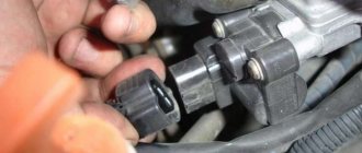
Before replacing the sensor, you need to make sure that it is receiving power and that all circuits are working properly. To do this, open the hood and disconnect the sensor connector (it is attached with a clamp to the cooling system pipe).
- Check the heating element circuit. We take the tester and connect its “minus” to the engine, and attach the “plus” to contact “B”. Turn on the ignition and look at the tester readings: it should show 12V. If the tester readings are less than 12V or are absent at all, then either the battery is discharged (which is unlikely) or the power circuit is open (we eliminate the malfunction). The ECU may also be faulty, but as a rule, the on-board computer immediately indicates this error.
- We check the circuit of the sensitive element. We measure the voltage between contacts “A” and “C”. minus on "C" plus on "A". The voltage should be 0.45V. If the voltage is absent or differs by 0.02 V or more, then the power circuit is faulty (you need to find and fix it) or the ECU is faulty (which is also unlikely).
You can fully check the sensor for functionality only with the help of an oscilloscope, which most car enthusiasts do not have, so I see no point in describing this situation. I will only say that to check it you will need to artificially lean and enrich the fuel mixture and look at the sensor readings. If the sensor has already traveled quite a bit - more than 100,000 km, then it can be safely replaced. Because, even if it is working, the sensitivity has noticeably deteriorated - which leads to extra costs for gasoline.
What is a lambda probe, principle of operation and its types
So, an air sensor is a small device that is installed in the exhaust manifold of any modern car and serves to assess the concentration of residual oxygen in the exhaust gases. Thanks to the readings of this device, the computer unit of your car receives data on the basis of which it prepares a combustible mixture. The lambda probe takes into account the residual oxygen concentration in the burned fuel and sends a signal to the electronics that the newly incoming combustible mixture needs to be either enriched or depleted of air. It goes without saying that any malfunction of the lambda probe may affect the performance of the car’s engine.
Remember! For combustion of 1 kg. mixture of fuel and air, you need to spend about 15 kg. oxygen.
What and how can you check the lambda?
To check, you will need a digital voltmeter (preferably an analog voltmeter, since its “sampling” time is much shorter than that of a digital one) and an oscilloscope, if possible, the measurements will be more accurate. Before checking, you should warm up the car since lambda operates correctly at temperatures above 300C°.
First we look for the heating wire:
We start the engine, do not disconnect the lambda connector. We connect the negative probe of the voltmeter (ordinary gauge) to the car body. We “poke” the positive probe on each wire contact and observe the voltmeter reading. When the positive wire of the heater is detected, the voltmeter should show a constant 12 V. Next, using the negative probe of the voltmeter, we try to find the negative wire of the heater. We connect to the remaining contacts of the sensor connector. If a negative contact is detected, the voltmeter will again show 12 V. The remaining wires are signal wires.
Lambda probe device
A modern air sensor is a small structural device inside which there are a number of interconnected parts.
Lambda probe design
- A metal body with threads. It is designed to fix the sensor in the mounting hole;
- Insulator made of ceramic;
- O-ring seal;
- Conductors;
- Protective shell with hole for ventilation;
- Contact;
- Ceramic tip;
- Electric heater;
- Gas outlet;
- Steel shell.
As a rule, the start of exhaust gas measurements occurs at a temperature of 310-400 degrees. It is at this temperature that the special filler in the sensor becomes electrically conductive. Until the temperature reaches the desired value, the car’s electronic control unit takes readings from other sensors, and only then from the lambda probe. The peculiarity of its operation is that the exhaust gases and atmospheric air are separated by a container with a current-generating composition. As a result of certain chemical effects on this capacity from the exhaust side and from the air side, a difference in oxygen concentration occurs, on the basis of which an electrical potential is generated. The values of this potential are sent to the vehicle control unit.
All oxygen sensors are divided into four types depending on the number of wires in their design:
1. Single-wire; 2. Two-wire; 3. Three-wire; 4. Four-wire.
Types of lambda sensors
All of the above lambda probes come in narrowband and broadband.
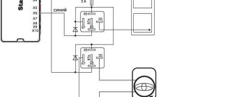
Design and connection diagram of the lambda probe/oxygen sensor, causes of breakdowns
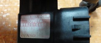
We bring to your attention technical information from DENSO on installing universal oxygen sensors.
How to properly install a universal oxygen sensor?
1. Cut the new oxygen sensor wires to the required length.
IMPORTANT: The new sensor connected to your existing connector must be the same length as the old sensor with the original connector.
2. Cut the wire from the old oxygen sensor.
3. Strip the wires of the new sensor and connector from insulation by approximately 7 mm each.
4. Crimp the butt joints of the sensor and conductor with special pliers and cover with heat shrink tubing (size 22–16).
5. Apply hot air to the shrink insulation until the connections are tightly sealed.
How to correctly connect the oxygen sensor wires by color?
1. Find out what wire colors are used on your old sensor.
2. Select the appropriate DENSO universal oxygen sensor. For all DENSO sensors there are two types of cable color combinations depending on the article number.
3. Connect the wires according to the data in the table below:
| Old (original) sensor | New DENSO sensor | |||
| Original sensor type 1 | Original sensor type 2 | Original sensor type 3 | Original sensor type 4 | Original sensor type 5 |
DOX-010.
DOX-011.
DOX-012.
DOX-013.
DOX-015.
The original sensor has 4 wires with the following color combination: 2 white, black and gray. The DENSO oxygen sensor art. no. is suitable for your vehicle. DOX-0107. Therefore, the wires should be connected as shown in the picture below:
Option 2: - Black wire on the ECU - Gray wire - ground - White wires - “-” and “+” for heating the probe - polarity does not matter. In this case, the white “-” is thrown to ground, and the white “+” to the ignition switch, or to the battery through a relay or something like that. Then it turns out that 2 native contacts remain empty.
1 Topic by serega 32 2014-11-30 00:15:08
- serega 32
- New member
- Inactive
- Registration: 2014-11-29
- Messages: 5 Thanks : 0
- Car: VAZ 2109i
Topic: oxygen sensor connector is broken, how to connect by color? VAZ 2109
The connector has come off. How can I now connect the wires without this connector? Which wire goes to which? they are not there by color. Tell me who has encountered this!?
Added: 2014-11-30 01:15:08
I forgot to say, the car is a VAZ 2109i
2 Reply from Serg 2014-11-30 08:52:53 (2014-11-30 08:59:27 edited by Serg)
- Serg
- Lada2111.rf fan
- Inactive
- Registration: 2013-07-29
- Messages: 830 Thanks : 363
- Car: 2111 dwg 2114 year 2008
Re: oxygen sensor connector is broken, how to connect by color? VAZ 2109
Which side did the sensor or harness come off from? The connector has the letters ABCD
sensor A - C sensor output (gray and black) B - D sensor heater (usually white wires)
harness A - pink to ecu 28 leg B - pinkblack +12v heater power supply C - red and white to ecu 10 leg D - white to ecu
3 Reply from serega 32 2014-11-30 11:41:24
- serega 32
- New member
- Inactive
- Registration: 2014-11-29
- Messages: 5 Thanks : 0
- Car: VAZ 2109i
Mechanical snag of the lambda probe (“screw-in”)
“Vvertysh” is a bushing made of bronze or heat-resistant steel. The inside of such a “spacer” and its cavities are filled with ceramic chips with a special catalytic coating. Due to this, the exhaust gases are burned faster, which, in turn, leads to different indicators of pulses 1 and 2 DC.
Important! Any snag is installed only on a working lambda probe.
A homemade lambda probe decoy, the diagram of which is presented below, is easy to manufacture. To do this you will need to prepare:
The blende is made on a processing lathe. If there is none, then you can contact a specialist by providing him with a drawing.
How the sensor works
Exhaust gases pass through the sensor, and clean air from the atmosphere enters it. Due to the different oxidizing properties of clean air and exhaust gases, a potential difference appears. These readings are sent to the ECU.
Hidden inside the sensor are a conductive element, electrodes, a signal contact and grounding. This whole system begins to work only after warming up to 300–400 oC. Only at this temperature is a solid electrolyte capable of conducting electricity.
Scheme of work
Repair work
After the car owner understands how to check the lambda probe at home, he needs to carry out repair work. You can do this yourself, or by turning to the experts. If you decide to carry out repairs yourself, you must follow the instructions.
First you need to determine where exactly the breakdown occurred. If a malfunction occurs with the circuit contacts, you will have to find the area of the break. At the same time, you need to check the contacts for oxidation and the lambda power supply. When oxidation occurs, treatment is carried out.
If the probe body is completely covered with carbon deposits, the elements must be cleaned. The treatment is carried out with special means that dissolve deposits. Do not use sandpaper or brushes.
Sensors are not that expensive, so we recommend trying to repair it yourself. If the fault cannot be repaired, then all that remains is to replace the parts.
Instructions for connecting an oxygen sensor
This instruction is for informational purposes only. It is strongly recommended that you entrust such a responsible procedure to a service center specialist with relevant experience.
- Remember or write down the location of the sensor wires. Disconnect the plug from the electronic component of the car without damaging or disconnecting the wires of the probe itself. Carefully remove the old lambda.
- Trim the wiring of the new universal sensor so that each subsequent cable is 4 cm shorter than the previous one (you can start from any one). Also shorten the cables from the connector of the old probe.
- Place special insulation and water protection on each of the wires (with the wide end of the water protection facing the point of connection of the wire).
- Remove 8 mm of insulation from each wire with wire cutters, then put on the contact connection and compress the structure so that the connection is perfect and no bare wires protrude. You should start the connection with the shortest wire, it’s easier.
- Move the waterproofing from both ends of the wiring to the connection, completely cover the connection with an insulating tube. Secure the structure with a hot hair dryer.
- Mount the sensor itself directly, removing the protective cap. The pinout of the lambda wires will help you lay out the new wiring in colors exactly as the old one was. It is necessary to connect and secure the wiring carefully so that it does not come into contact with the converter, manifold or other parts of the car that heat up to high temperatures.
Timely replacement of the lambda probe is very important. If the car's ECU does not receive reliable information about the level of oxygen in the exhaust, it will work based on average parameters, so the fuel-air mixture will not be optimal - this will negatively affect the condition of the car.
Our car service center in St. Petersburg specializes in diagnosing and repairing exhaust systems of a wide variety of cars, from VAZ to foreign cars. We guarantee high quality repairs and short terms. Don’t risk your equipment - turning to professionals will save a lot of nerves, and in the long run, money, because independent repairs based on advice from forums can only lead to more serious malfunctions.
Replacement sensors
Oxygen sensor for VAZ 2110
If you have come to such a need as replacing a lambda probe, you should think about which sample to choose.
There is always the opportunity to choose the original version, for example, with catalog number 89465-32160 for Toyota Vista, as well as 89465-48130, 89465-48020 for Toyota Harrier and Kluger; many car enthusiasts speak well of Toyota 89465-20270 (for 3s-fe, 4s engines -fe), however, those who want to save money are looking for alternatives. An alternative could even be an analogue for the VAZ 2110 (Bosch 0 258 005 133), but you will have to resolder the wires. However, if you contact a service center where good craftsmen work, or if you yourself have experience in certain types of work on a car, this will not be a problem.
You can choose either an original part, or just a factory one, or, as mentioned, even from another car, the main thing is to install it properly. This work will be quickly completed in the workshop, and the car will once again return to its economical fuel consumption and environmental parameters, which is what is actually required. It is worth remembering that the accuracy of the readings and, consequently, the amount of fuel consumed by the car may depend on the quality and correct installation of the probe. So the work should be trusted only to competent specialists.
Checking the voltage
A way to check the voltage in the heating circuit with your own hands:
- Turn on the ignition without removing the connector from the lambda probe.
- Connect the probes to the heating circuit.
- Look at the multimeter values: normally they are the same as the voltage on the battery - 12 V.
Two points:
- “+” is directed to the sensor from the battery using a fuse. If it is not there, you need to ring this circuit.
- “—” comes from the management block. If not found, test the terminals of the “lambda probe - electronic control unit” line.
How to measure the reference voltage:
- Turn on the ignition.
- Measure the voltage between ground and signal wiring.
- The normal reading is approximately 0.45-0.50 V.
Useful video on how to check a lambda probe with a multimeter for serviceability:
It is important to check the signal, that is, the sensitivity of the tip. Instructions on how to check an oxygen sensor with a multimeter:
- Start the car and warm up the engine to seven to eight tens of degrees. Bring it to three thousand revolutions per minute and hold it there for two to three minutes so that the sensor is warmed up.
- Connect the negative wire of the multimeter to the engine body (to the ground of the car). Positive to signal wiring (usually black wiring).
- Look at the multimeter readings. Normally they vary from 0.2 to 1 V, changing frequently. In about ten seconds, the sensor turns on the same number of times. If the multimeter shows 0.5 V but does not turn on, the sensor is faulty.
- Press the gas pedal to the floor and release sharply. The working sensor has a value of 1 V, after which it drops to 0. If, when manipulating the pedal, the values do not change and show, say, 0.4 V, the lambda probe is faulty.
If there is no voltage at all, diagnose the wiring: use a multimeter to test all the cables that connect the relay to the ignition switch.
Operating principle of the sensor
Today, cars can use different types of oxygen systems. To understand how to check whether the lambda probe is working, you need to study its operating principle. The sensor itself consists of a heating element, several electrodes and an electrolyte. The functioning of the λ probe is simple, but has its own nuances.
In order for the device to determine the “incorrectness” of the readings, it needs to compare the results obtained with something. Therefore, it measures the air itself and the gases remaining after the combustion of the air-fuel mixture (FA). The measurement results are transmitted in the form of pulses to the ECU. This is where electrodes come into play and take measurements by reacting with oxygen and exhaust. The impulse is sent to the ECU, where it compares the results with the data “in memory”.
Nowadays on many cars the exhaust system is equipped with two sensors. They measure residual oxygen and evaluate the efficiency of the neutralizer. Thanks to this system, the environment is not so polluted. But if the car owner refuels the car with low-quality fuel a couple of times, the converter will break. Even if you follow all the rules for operating the system, the neutralizer may still become faulty, because it has a certain working resource.
The main causes of lambda probe malfunctions and the consequences of its breakdown
Once we have defined the concept and operating features of the oxygen sensor, we can conclude that it plays a key function in the normal operation of the internal combustion engine. So what can cause the lambda probe to break down and fail? There are two aspects to this issue: external factors and internal ones, about which read below.
- Coolant or brake fluid leaking into the sensor housing;
- Caring for the sensor with means that are not intended for such purposes;
- Poor quality fuel with excessive lead content;
- Overheating of the sensor, which also happens when using bad fuel.
After the lambda probe fails, your car will begin to show certain signs:
- Significant jerks when moving;
- Excessive fuel consumption;
- Poor performance of the catalyst;
- Floating engine speed;
- Excess toxic waste in exhaust gases.
The seriousness of all of the above should prompt the driver to check the lambda probe almost every 10 thousand km. Its complete replacement is desirable after every 40,000 km.
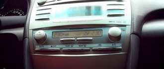
Checking the oxygen sensor using self-test
The cause of the increased consumption is identified by checking the 3S-Fe lambda probe in self-diagnosis mode. Compliance with the following initial conditions is mandatory:
- The car battery produces at least 11 volts of voltage;
- the engine is warmed up to operating temperature (80-90°C);
- The manual transmission lever is in the neutral position (on cars with automatic transmission – selector position “P”);
- the throttle valve is closed;
- additional equipment that consumes electricity is turned off.
Click to enlarge
To obtain a verification code you need to do the following:
- turn on the ignition, do not start the engine (the “CHECK ENGINE” should light up and not go out);
- Using a jumper, connect pins 4 and 13 (CG and TC, respectively) to the diagnostic connector (DLC3).
If the actions are performed correctly, the indicator will first go out and then begin to flash. No flashing is a sign that the connectors have not been closed properly. The code is read by the number of blinks of the indicator.
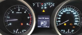
Code identification
If there is no malfunction of the 3S-Fe lambda probe, the indicator will light up and go out at intervals of a quarter of a second. If there is a problem with the oxygen sensor, the indicator will flash every half second, and the number of flashes corresponds to one of the code numbers. They are two-digit, so after the first sequence of flashes (the first number), after one and a half seconds the second sequence (the second number) begins.
Click to enlarge
If there are more faults, the time interval between the displayed codes will be 2.5 seconds. After all errors are displayed after 4.5 seconds, the cycle is repeated, and the display is increasing (for example, 21 will be displayed first, then 25, etc.).
Some engine control systems detect a problem using a two-stage algorithm. When it is initially detected, it is temporarily recorded in the memory of the control unit. If the error occurs again, the driver is given a signal in the form of a lit “CHECK ENGINE” indicator. An important nuance is to turn off the ignition between two stages (driving tests).
Checking the 3S-Fe oxygen sensor for malfunction is completed by removing the jumper from the diagnostic connector. Error codes stored in memory can be reset (erased).
Erase errors
Since the code is not automatically deleted from memory after replacing or cleaning the lambda probe, it must be erased. To do this, with the ignition off, the one responsible for the electronic fuel injection system (EFI) is removed from the fuse block. The shutdown time depends on weather conditions - the colder it is, the longer the fuse does not return to its seat.
Oxygen sensor errors can also be reset by removing the wire from the negative terminal of the battery. In this case, you need to take into account the fact that data from other systems with memory will be reset to the car. A check after installing the fuse will show either a normal operation code or the presence of the same malfunction. Further actions of the car owner are repeated cleaning or replacement of the element with a new one.
A little history
This element can be considered the most popular among all other sensors in the car. Automotive diagnostic specialists often deal with it. There have been oxygen sensors before, this is not a new thing. The first lambda probe was a kind of sensitive element without heaters. The element was heated by the temperature of the exhaust gases. The heating process took some time.
As the years passed, the environmental situation around the world constantly deteriorated. Therefore, it was necessary to take measures to tighten the harmfulness and toxicity. The requirements for cars have become stricter. At this point, the sensor began to develop and evolve. It was equipped with a special heater.
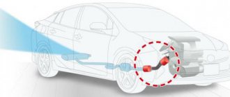
Why is a lambda probe needed in a car, location
A lambda probe is necessary to measure the oxygen content coefficient in a combustible mixture. It is always installed in the area of the exhaust pipe before the catalyst and measures the volume of unburned oxygen in the combustion products. This information will allow the ECU to prepare the optimal mixture.
A mixture containing 14.7 parts air and one part fuel burns most efficiently. These are optimal indicators; if oxygen is present in large quantities, then the mixture is lean; if there is less air, then it is rich.
General connection rules
Since 1999, cars have typically been equipped with zirconium or titanium oxygen sensors that meet certain standards regarding wire colors. The number of wires is usually four. Below are tables for both probes. In the vast majority of cases, to check you will need the first table - for zirconium sensors, but occasionally you can find titanium ones.
If, during reconciliation, it is revealed that the combination of colors in one of the columns of the table corresponds to the colors of the lambda probe wires of your car, this means that the probe is structurally designed this way, and the pinout should be done in accordance with these data.
| Purpose | Color combinations (zirconium probes) | ||||
| 1 | 2 | 3 | 5 | 6 | |
| Signal (plus) | Blue | Black | Black | Violet | Green |
| Signal (minus) | White | Grey | Grey | Beige | White |
| Heater (plus) | Black | Violet | White | Brown | Black |
| Heater (minus) | Black | White | White | Brown | Black |
| Purpose | Color combinations (titanium probes) | ||
| 1 | 2 | ||
| Signal (plus) | Grey | Yellow | |
| Signal (minus) | Grey | Black | |
| Heater (plus) | Black | Red | |
| Heater (minus) | Black | White | |
Tip for using the table:
- Check the oxygen sensor wires in your car.
- Compare their colors with the columns in the tables.
- If the colors completely match one of them, then this is exactly the design you have and you should build on it.
For example, your lambda probe is equipped with four wires of the following colors: beige, purple and two brown. The same combination is indicated in the fourth column of the first table. This means you have a zirconium device with the same wires and operating principle. Next, we look at the first column of the same table and see that the arrangement of the wires according to the diagram is as follows: the beige one goes to ground (minus), the purple one is responsible for transmitting signal data, and the two brown ones are needed for the operation of the heater. This way you can accurately identify the wires by their shades.