In order to prevent the car's wheels from locking and, as a result, skidding on the road, the Toyota Corolla uses an anti-lock braking system. The purpose of a fully automated anti-lock system is to maintain controllability in the event of emergency braking of the vehicle and to prevent it from slipping uncontrollably.
Rice. 1. Braking trajectories during braking
Anti-blocking operates according to the following principles:
- at the initial moment of braking, special sensors on the wheels record the initial blocking impulse;
- by means of feedback via an electrical wire, a signal is generated that controls the weakening of the force of the hydraulic cylinders even before the start of slipping, the tires regain traction with the road;
- after spinning the wheel, the maximum braking force is again created in the hydraulic cylinders;
Thanks to the repeated repetition of this simple electro-hydromechanical chain, the braking distance is practically no longer than with continuous blocking, but controllability is completely preserved. This allows you to avoid skidding, moving the car into oncoming traffic or onto the side of the road.
The device of the ABS complex
Main components of the anti-lock system:
- speed sensors of front and rear wheels;
- hydraulic valves of the hydraulic brake system;
- elements of the channel for exchanging information between sensors and hydraulic system valves.
Anti-lock braking is especially important for drivers who do not have much experience, since it is enough to hold the brake pedal to the floor, and the system does the rest. But on sections of the road with a loose surface in the form of gravel, sand or snow, the braking distance turns out to be longer than when braking by completely and continuously blocking the brakes. After all, the tires do not bury themselves in the loose mass, but slide along its surface.
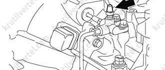
Rice. 2. Installation locations of ABS units in the car
In Fig. Figure 2 shows a diagram of the location of the main components of the auto-locking system in the overall structure of the car.
The arrows indicate the following elements:
- Anti-lock complex drive;
- Control relay;
- Control unit and photodiode for turning on the anti-lock braking system;
- Front wheel speed sensor;
- Speed sensor rotor in the front wheel;
- Speed sensor rotor in the rear wheel;
- Rear wheel speed sensor.
The effect of the anti-lock braking system is to maintain the stability and controllability of the car while optimally reducing the speed. All this happens by monitoring the rotation speed of each wheel and periodically releasing pressure in its brake hydraulic line.
Toyota Corolla security system, ABS
The Toyota Corolla is equipped with a set of safety systems designed to reduce the likelihood of an emergency and, in the event of a traffic accident, to provide maximum protection for the driver and passengers.
ABS - anti-lock braking system. Prevents wheel locking during emergency braking or when braking on slippery roads. EBD - brake force distribution system. It is part of the anti-lock braking system. TRC - traction control system. If the drive wheels slip during acceleration, the system automatically reduces engine torque and brakes the wheel that has slipped, helping to restore traction. VSC - exchange rate stability system. Automatically triggers when it detects a skid due to sudden steering or insufficient contact with a slippery road. By braking one wheel or another and changing the engine torque, it brings the car out of a skid and helps the driver stabilize its trajectory. BA - emergency braking assistance system. Provides emergency braking when the driver presses the brake pedal sharply, but not hard enough. To do this, the system measures how quickly and with what force the pedal is pressed, and then, if necessary, instantly increases the pressure in the brake system to the maximum effective. ABS Toyota Corolla
The anti-lock brake system (ABS) consists of wheel speed sensors, a switch on the brake pedal, a hydroelectronic control module and warning lights in the instrument cluster. The anti-lock braking system includes brake force distribution (EBD) and a self-diagnosis system that detects malfunctions of system components. ABS serves to regulate the pressure in the brake mechanisms of all wheels when braking in difficult road conditions and thereby prevents wheel locking. The ABS system provides the following advantages: - avoiding obstacles with a higher degree of safety, including during emergency braking; — reduction of braking distance during emergency braking while maintaining directional stability and controllability of the vehicle, 8 including when turning. In the event of a system malfunction, diagnostic functions and maintenance of operation in the event of system failures are provided. The hydroelectronic control module receives information about vehicle speed, direction of travel and road conditions from the wheel speed sensors and throttle position sensor. After turning on the ignition, the control unit supplies voltage to the wheel speed sensors. They use the Hall effect and generate an output signal in the form of pulses. The signal changes in proportion to the rotation frequency of the sensor pulse ring. Based on this information, the control unit determines the optimal wheel braking mode. There are the following operating modes of the anti-lock braking system: - normal braking mode. During normal braking, the intake valve is open and the exhaust valve is closed. When you press the brake pedal, brake fluid is pressurized into the working cylinder and operates the wheel brakes. When the brake pedal is released, brake fluid returns to the master cylinder through the inlet and check valves; — emergency braking mode. If a wheel locks during emergency braking, the module sends a command to the pump electric motor to reduce the brake fluid supply, then voltage is applied to each solenoid valve. The inlet valve closes and the supply of brake fluid from the master cylinder and pump is shut off; The exhaust valve opens and brake fluid flows from the working cylinder into the main cylinder and then into the reservoir, which causes a decrease in pressure; — pressure maintenance mode. When the pressure in the working cylinder decreases to a maximum, the module issues a command to maintain brake fluid pressure; voltage is supplied to the intake valve and not to the exhaust valve. In this case, the intake and exhaust valves are closed and the brake fluid does not leave the working cylinder; — pressure increase mode. If the module determines that the wheel is not blocked, then voltage is not supplied to the solenoid valves, and the brake fluid enters the working cylinder through the inlet valve, the pressure in which increases. To diagnose and repair the anti-lock brake system, special equipment and accessories are required, so if it fails, contact a specialized service station.
CHECKING ABS SYSTEM FAULT CODES AND THEIR REMOVAL
If the anti-lock brake system warning light comes on in the instrument cluster, the diagnostic code can be used to determine the cause of the system malfunction. To check the DTCs, do the following: 1. Pry up the latch... 2. ...and open the cover of the diagnostic connector.
3. Install a test lamp between the diagnostic connector contacts “4” and “13” to read the anti-lock brake system fault codes. 4. Set the ignition key (lock) to the “ON” position. 5. After 4 s, the indicator lamp will start flashing, for example: flash, pause (approximately 1.5 s), flash, flash, flash (serially at 4 s intervals). By counting the number of flashes before and after the pause, we determine the fault code. If there are two or more faults in the system, a series of flashes are repeated in blocks in which fault codes are displayed sequentially at intervals of 2.5 s, and the blocks are repeated at intervals of 4 s. If the control lamp does not light up, check the connections of terminal “4” to ground and terminal “13” to the control unit. If there are no faults, the warning lamp flashes at intervals of 0.25 s. 6. Set the ignition key to the “ACC” position and disconnect the warning lamp from the diagnostic connector. 7. Set the steering wheel to the straight-ahead position of the vehicle.
8. Install a test lamp between pins “4” and “12” of the diagnostic connector to read the anti-lock brake system fault codes. 9. Set the ignition key to the “ON” position. The warning light should first come on for a few seconds and then start flashing. If the control lamp does not light up, check the connections of terminal “4” to “ground” and terminal “12” to the control unit. 10. Take a test drive while driving the car in a straight line at a speed of at least 45 km/h and no more than 80 km/h. While driving, the warning light should go out. 11. Stop the car - the warning light should flash.
12. Install an additional test lamp between pins “4” and “13” of the diagnostic connector and perform steps 5. 13. To exit the ABS fault code checking mode, turn off the ignition and remove the warning lights. To eliminate fault codes from the control unit memory, do the following. 1. Pry up the latch. 2. ...and open the cover of the diagnostic connector. 3. Install a test lamp between pins “4” and “13” of the diagnostic connector to read the anti-lock brake system fault codes.
4. Set the ignition key (lock) to the “ON” position. 5. Press the brake pedal at least 8 times within 5 seconds. 6. The control lamp should show the absence of malfunctions, i.e. flash at 0.25 s intervals. Otherwise, repeat the operations in paragraphs. 4 and 5. 7. Turn off the ignition and remove the warning lamp.
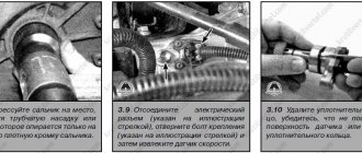
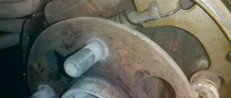
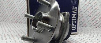
REPLACING WHEEL SPEED SENSORS Toyota Corolla front wheel speed sensor
installed in the hole in the steering knuckle of the front suspension and is removed complete with the wiring harness.
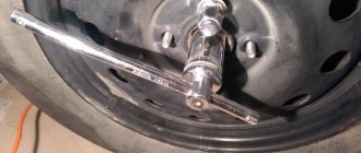
Replacement of the sensor on the left front wheel is shown. The sensor on the right front wheel is replaced in the same way. 1. Disconnect the wire from the negative terminal of the battery. 2. Brake the rear wheels, install wheel chocks (“shoes”) under them, loosen the front wheel nuts, lift the front of the car, place it on reliable supports and remove the front wheel. 3. Remove the front wheel arch liner. 4. Remove the bolt securing the front wheel speed sensor to the steering knuckle. 5. Remove the sensor from the hole in the fist. 6. Using a screwdriver, open the lower clamp and remove the sensor wiring harness. 7. Remove the bolt and disconnect the lower mounting bracket for the wiring harness from the front suspension strut. 8. Remove the bolt and disconnect the upper mounting bracket for the wiring harness from the body. 9. Using a screwdriver, open the upper lock and remove the front wheel speed sensor wiring harness. 10. Press out the block fastening clamp, disconnect the wiring harness block and remove the front wheel speed sensor assembly with the wiring harness. 11. Install the front wheel speed sensor and all removed parts in the reverse order of removal. When installing the front wheel speed sensor, align the hole in the front wheel speed sensor housing with the threaded hole in the knuckle. During installation, do not rotate the sensor around its longitudinal axis. The increase in resistance to movement of the sensor should only be felt the last 2 mm before it is completely seated in the fist. If the sensor enters the knuckle hole with great resistance from the very beginning of installation, remove the sensor and eliminate the cause of the jamming (dirt, burr on the body, etc.) It is strictly forbidden to press in the wheel speed sensor with a hammer. The Toyota Corolla rear wheel speed sensor
is installed in the rear wheel hub and is removed as an assembly with the hub. If it is necessary to replace the sensor, replace the rear wheel hub assembly. You will need: a flat blade screwdriver, 14" and 17" wrenches, a 14" socket with an extension. Replacement of the sensor on the left rear wheel is shown. The sensor on the right rear wheel is replaced in the same way. 1. Disconnect the wire from the negative terminal of the battery. 2. Engage 1st gear (move the automatic transmission selector to the “P” position), install wheel chocks (“shoes”) under the front wheels, loosen the rear wheel nuts, lift the rear of the car, place it on reliable supports and remove the rear wheel . 3. Use a screwdriver to pry off the latch. 4 . .open and remove the housing of the rear wheel speed sensor pad. 5. Disconnect the rear wheel speed sensor wiring harness connector. 6. Remove the brake caliper 7. Remove the brake disc 8. Remove the rear wheel hub 9. Install the rear wheel hub assembly with the speed sensor and all removed parts in the reverse order of removal.
REMOVAL OF THE HYDROELECTRONIC MODULE
Hydroelectronic ABS module
: 1 - pipeline of the primary circuit of the main brake cylinder; 2 — pipeline of the second circuit of the main brake cylinder; 3 - pump; 4.5 — bolts securing the module to the bracket; b — bracket for attaching the module to the body; 7 — pipeline of the working brake cylinder of the right front wheel; 8 — pipeline of the working brake cylinder of the left rear wheel; 9 — pipeline of the working brake cylinder of the right rear wheel; 10 — pipeline of the working brake cylinder of the left front wheel; 11 — wiring harness block
The hydroelectronic module for controlling the anti-lock brake system is installed on bracket 6 (Fig. 13.1) in the engine compartment on the left and is attached to the bracket through rubber pads with bolts 4 and 5... and special keys “10”, “14” for loosening the pipeline nuts. 1. Disconnect the wire from the negative terminal of the battery. 2. Pump out the brake fluid from the master cylinder reservoir. 3. Unscrew the six fastening nuts and disconnect the hydraulic electronic module pipes.
4. Slide the wiring harness block lock up. 5. Disconnect the wiring harness connector from the hydroelectronic module. 6. Unscrew the two front and one bottom mounting bolts and remove the hydroelectronic module. 7. Install the hydroelectronic anti-lock brake control module and all removed parts in the reverse order of removal. 8. Bleed the brake system
Passive safety system Toyota Corolla
Layout of airbags
: 1 - driver's airbag; 2 — passenger airbag; 3 — side airbags; 4 - curtains
The actual airbags installed in the vehicle may appear different from those shown in the illustration.
The passive safety system (SRS) of the Toyota Corolla, Auris combines 1 and 2 front and 3 side airbags for the driver and front passenger, 4 inflatable side curtains (depending on the configuration), height-adjustable seat belts for the driver and front passenger with pretensioners, inertial seat belts for rear passengers, ISOFIX child seat anchorages, front seat with WIL rear impact protection system to prevent spinal injuries.
Airbags are not a replacement for seat belts.
Moreover, when the car is moving, the driver and front passenger must be wearing seat belts, since in the event of a traffic accident, a deployed airbag itself can cause serious injury to a person who is not wearing a seat belt. In addition, rear seat passengers must wear seat belts. In the event of an accident, an unbelted passenger in the rear seat can cause injury and serious injury to all passengers in the vehicle. Do not install or place any accessories on the passenger front panel above the glove box in your vehicle. Such objects may move suddenly and cause injury when the passenger airbag inflates. When installing an air freshener inside the cabin, avoid placing it near instruments or on the surface of the dashboard. Such objects may move suddenly and cause injury when the passenger airbag inflates. The deployment of airbags may be accompanied by a loud noise and the spread of fine dust throughout the cabin. This is normal since the airbags, when inoperative, are packed in this powder. Dust released during the expansion of pillows can cause irritation to the skin or eyes, and increase the asthmatic reaction of some people. After an accident in which the airbags deploy, thoroughly wash all exposed skin with warm water and soap. The SRS airbag system is designed to deploy only when the force of the frontal impact is sufficiently large and its direction makes an angle of no more than 30° with the longitudinal axis of the vehicle. In addition, it is a single use system. Front airbags are not designed to inflate in the event of a side collision, rear impact, or rollover. Children under the age of 12 must be transported using a special child restraint device. The use of a child restraint system is determined by the Road Traffic Regulations, and its fastening in the vehicle interior is determined by the manufacturer’s recommendations. It is the driver's responsibility to ensure that the passenger's front airbag switch is positioned correctly. The passenger's front airbag should only be turned off when the ignition is off, otherwise the airbag system control unit may fail. The SRS system includes the following elements: - the driver's airbag module, located in the steering wheel hub and consisting of a folded airbag shell and a gas generator; — driver’s foot airbag module (in a variant), located in the lower part of the instrument panel; — the front passenger airbag module, located under the instrument panel on the passenger side and consisting of a folded airbag shell and a gas generator. Differs from the driver's airbag in shape and larger volume; — driver and front passenger side airbag modules located in the outer side parts of the front seat backrests and consisting of a folded airbag shell and a gas generator; — curtain airbag modules for the driver and passengers (in a variant version), located under the facings of the front and rear pillars of the body and consisting of a folded airbag shell and a gas generator. The airbag locations are indicated by the “SRS AIRBAG” symbol; — modules of front seat belt pretensioners, combined with inertial reels, located in the central pillars of the body, behind the lower trim of the pillar; — an electronic control unit installed in the instrument panel, under the heating, air conditioning, and interior ventilation control unit. The ECU contains micromechanical sensors that measure the longitudinal and lateral acceleration of the vehicle during a collision. The ECU estimates the severity of the impact by comparing the values it receives from the front impact sensors, side impact sensors and internal electronic sensors with a set value. If the deceleration signal due to a frontal or side impact exceeds a predetermined value, the computer triggers the activation of the seat belt pretensioners and deployment of the associated airbags. If a vehicle's battery is destroyed during an accident, the voltage hold circuit in the ECU will still be able to activate the airbags for some time after the impact; — frontal and side impact sensors that transmit acceleration information to the system control unit. Frontal impact sensors
are located on the side members of the car body in the front part of the engine compartment.
The side impact sensors are located on the B-pillar, behind the lower pillar trim. The strength and direction of impact during a traffic accident is determined by the electronic control unit (ECU) of the passive safety system using impact sensors. Based on sensor signals, the control unit activates airbags and front seat belt tensioners; - seat belts. When an impact of a certain force occurs, the ECU, having received signals from the impact sensors, increases the tension of the belts before activating the airbags, issuing a command to the pyrotechnic elements of the pretensioners. The latter provide a timely response to emergency deceleration of the car, pulling the driver and front passenger to the backs of the seats, preventing them from further moving forward by inertia and getting injured from a deployed airbag; — head restraints installed in the backs of all seats prevent damage to the cervical vertebrae of people sitting in the car in the event of a strong rear impact and when the airbags are deployed. The front seat head restraints feature WIL technology, which further reduces the risk of neck and spine injuries in rear impacts. The headrests of the front and rear seats can be adjusted in height by pressing the lock and moving them up or down to the required height. The optimal position of the headrest is one in which its upper edge is located at the same level as the top of the head. For very tall people, raise the head restraint to its highest position; for very short people, lower the head restraint to its lowest position. — passive safety system indicators. The high pressure passive safety system fault indicator (with a red filter) is located on the right side of the instrument cluster. Lights up when the ignition is turned on, stays on for about a minute, and goes off if the system is working properly. If the warning light does not go off (or comes on while driving), it means that there is a malfunction in the passive safety system. If the warning light comes on, immediately contact a car service center. In addition to the possible failure of the airbag in an emergency, it may unexpectedly deploy while driving, which will lead to serious consequences. warning light unit
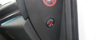
is located on the center console. The airbag deactivation warning lamp A comes on and stays on if the passenger's front airbag is deactivated. The airbag warning light B comes on and stays on if the passenger's front airbag is activated. The front passenger seat belt warning light B lights up and flashes when the ignition is switched on if the front passenger seat belt is not fastened. The presence of a front passenger is detected by a special sensor in the front seat. The driver's seat belt warning light is located on the right side of the instrument cluster; it lights up and flashes when the ignition is on if the driver's seat belt is not fastened; — the front passenger airbag switch is located on the side surface of the instrument panel, on the right side. The switch turns off the front passenger airbag when a child is transported in the front passenger seat. Do not turn off the front passenger airbag unnecessarily, except when a child restraint is installed in the front seat. This subsection describes the removal and installation of driver and front passenger airbags, and the removal and installation of seat belts. Side and curtain airbags should only be removed by a workshop by specially trained personnel.
REMOVAL AND INSTALLATION OF DRIVER AIR BAG
You will need: a flat-blade screwdriver, a TORX TZO wrench. 1. Disconnect the wire from the negative terminal of the battery. Attempting to remove an airbag module without disconnecting its power supply may result in unexpected deployment of the airbag. You can begin subsequent operations to remove the airbag only after the activator capacitor has completely discharged. To discharge the capacitor, you must wait at least one minute after turning off the power supply. Before replacing a fuse or disconnecting the battery, turn the ignition key to the “LOCK” position and remove it from the ignition. Never remove or replace fuses related to the airbag system while the ignition key is in the "ON" position. Failure to heed this warning will cause the airbag warning light to illuminate. To turn off the alarm, you will have to contact a specialized auto repair center. 2. Use a screwdriver to pry off the latches and remove the plugs on the left and right sides of the steering wheel. 3. Using a TORX TZO wrench, remove the screws securing the steering wheel pad on the left and right sides. 4. Pull towards you and move the pad with the airbag away from the steering wheel. 5. Disconnect the horn terminal from the inside of the steering wheel pad. 6. Using a screwdriver, pull out the lock of the airbag wiring harness block... 7. ...disconnect the wiring harness block and remove the airbag. Do not disassemble the airbag module. Do not drop the airbag module and do not allow water, grease or oil to come into contact with it. The airbag module must not be exposed to temperatures above 95 °C 8. Install the driver's airbag and all removed parts in the reverse order of removal. When installing the module in the steering wheel of a car, be outside the deployment zone of the airbag. When you first turn on the ignition after installing the airbag module in the vehicle, stand outside the vehicle and turn on the ignition switch with your hand under the steering column.
REMOVAL AND INSTALLATION OF THE FRONT PASSENGER AIR BAG You will need: flat-blade and Phillips-blade screwdrivers, a 10mm wrench. 1. Disconnect the wire from the negative terminal of the battery. Attempting to remove an airbag module without disconnecting its power supply may result in unexpected deployment of the airbag. You can begin subsequent operations to remove the airbag only after the activator capacitor has completely discharged. To discharge the capacitor, you must wait at least one minute after turning off the power supply. 2. Remove the top of the instrument panel
3. From the inside of the instrument panel, remove the two screws securing the airbag brackets. 4. Disconnect the holders of the front and rear parts.. 5. ...and remove the airbag. Do not disassemble the airbag module.
Do not drop the airbag module and do not allow water, grease or oil to come into contact with it.
The airbag module must not be exposed to temperatures above 95°C. 6. Install the front passenger airbag and all removed parts in the reverse order of removal. When you turn on the ignition for the first time after installing the airbag module in the vehicle, stand outside the vehicle and turn on the ignition switch by reaching under the steering column.
REMOVAL AND INSTALLATION OF THE ELECTRONIC CONTROL UNIT FOR THE PASSIVE SAFETY SYSTEM You will need: flat-blade and Phillips-blade screwdrivers, “10”, “12” keys.
The electronic control unit
(ECU) for the passive safety system is located in the central part of the instrument panel under the heating, air conditioning and interior ventilation system unit. For clarity, the work is shown on a car with the instrument panel removed. 1. Disconnect the wire from the negative terminal of the battery. After disconnecting the wire from the negative terminal of the battery, you must wait at least a minute, and only then can you disconnect the ECU wiring harness block. 2. Remove the floor tunnel lining 3. On the center console, remove the ashtray unit, the security system display unit, the control unit for the heating, air conditioning and interior ventilation system 4. Overcoming the resistance of the clamps, disconnect the central air duct from the heating, air conditioning and interior ventilation system unit and remove the air duct . 5. Press the lever lock and turn the wiring harness block fixing lever to the left. 6. Disconnect the ECU wiring harness block. 7. Remove the ECU front mounting bolt. 8. Remove the left and right ECU rear mounting bolts. 9. Pull towards you and remove the electronic control unit for the passive safety system. 10. Install the passive safety system control unit and all removed parts in the reverse order of removal.
Replacing a Toyota Corolla shock sensor
You will need: flat-blade and Phillips-blade screwdrivers, 10mm wrench. To replace the side impact sensor, do the following: 1. Disconnect the wire from the negative terminal of the battery. After disconnecting the wire from the negative terminal of the battery, you must wait at least one minute, and only after that you can begin to remove the sensor. Replacement of the spruce side side impact sensor is indicated. The side impact sensor on the right side is replaced in the same way. 2. Remove the lower trim of the B-pillar 3. Slide the wiring harness block clamp... 4. ...and disconnect the side impact sensor block. 5. Remove the bolt securing the sensor to the central pillar of the body. 6. Remove the side impact sensor. 7. Install the side impact sensor and all removed parts in the reverse order of removal. To replace the front impact sensors, do the following: 1. Disconnect the wire from the negative terminal of the battery. After disconnecting the wire from the negative terminal of the battery, you must wait at least one minute, and only after that you can begin to remove the sensor. Frontal impact sensors are located on the side members of the car body in the front part of the engine compartment. Replacement of the front impact sensor on the left side of the vehicle is shown. The front impact sensor on the right side is replaced in the same way.
2. Remove the front trim of the engine compartment 3 Remove the front bumper 4. Unscrew the fastening bolt... 5. ...and disconnect the sensor from the side member 6. Press the clamps, open and remove the protective cover of the wiring harness block. 7. Disconnect the wiring harness connector and remove the left front impact sensor. 8. Remove the right front impact sensor in the same way. 9. Install the front impact sensors and all removed parts in the reverse order of removal.
Tags Toyota Corolla, abs, security system
ABS electronic module
The anti-lock control unit is located next to the instrument panel. It includes and processes electrical impulses from wheel speed sensors. After processing the information, the unit sends signals to the cavity valves of the anti-lock drive.
Also, with the help of an electronic module, the performance of the entire complex is constantly monitored and tested. In the event of a malfunction, a light signal flashes on the dashboard, warning the driver of an emergency situation. The electronics unit is also capable of generating a fault code and storing it for a service station specialist.
A photodiode signal that flashes from time to time warns the driver that deviations in operating parameters are possible in the complex. In this case, you should check the reliability of the connection of the wires from the sensors to the electronic unit, the fuses, and the filling of the master cylinder reservoir with brake fluid.
If after this the warning signals continue to appear, then you should contact a specialized Toyota Corolla repair and maintenance center.
Why might errors occur?
The Corolla 150 is a reliable car, but Russian operating conditions may not have the best effect on the sensors. Most often, if the ABS icon appears on the dashboard, you need to check for faulty ABS sensor.
When you turn on the engine, the light should light up and go out after a certain time: this is a normal reaction of the system to turning on, however, if the ABS lamp turns off again, this already indicates a malfunction in the control unit or sensor. The notification may come on for the following reasons: the fuses have failed, the electrical system wires do not transmit impulses well, the sensor itself is faulty, the control unit has failed, or communication with the sensor has been lost.
If the lamp does not light constantly, but flashes frequently, then the problem may be in the operation of the car’s generator.
Anti-lock braking system drive for Toyota Corolla
The device includes a hydraulic pump and a multi-cavity housing with four magnetic valves. In the drive cavity of each wheel, the required pressure is created and regulated using its own valve. Signals for opening and closing cavity valves come from wheel rotation sensors.
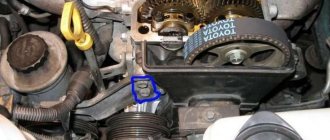
Photo 1. ABS block of Toyota Corolla Fielder
The block can be seen under the hood of the engine compartment. It is located next to the brake cylinder and is connected to it by metal pipes for the flow of brake fluid.
How to check the fault?
It is best to check the operation of the Toyota Corolla ABS at a specialized car service center, where they can determine exactly what the problem is and fix it. If the car has an on-board computer, the technician will be able to read the error number and understand what is wrong.
However, some manipulations can be done independently.
It is recommended to start checking with fuses; if you don’t know how to disable ABS, but want to do it, it’s better to start with them too.
Without this element the device will not work. You can find the fuse box under the hood: check the fuses, connectors, and replace blown ones if necessary.
The control unit is also located under the hood. You can find the control unit by the tubes coming from the brakes and wires. The control unit may receive mechanical damage, so you must first inspect it visually. You will first need to remove the electrical wire from it. Check whether water has entered the unit: if it is wet, it needs to be dried.
After washing, a similar problem may also occur, as moisture gets on the wiring. The wet wire shorts out and the wheel sensor cannot communicate with other parts of the system; in this situation you need to wait until the wire dries.
Major repairs may be required if the wheel bearing is faulty. To do this, you need to accelerate the car to at least 80 km/h and listen: if you hear a distinct hum, then the bearing needs to be replaced. Most often the front one breaks, but if, for example, the rear left one requires repair, the bearings are replaced on both sides of the axle. If the rear bearing is faulty, it is not necessary to change the front right or left element.
In the same situation, you can check the brakes. Pay attention to how the car behaves when you press the pedal, whether it skids, whether you feel a blow to it from a working ABS. You will quickly understand if the system is not working. If the ABS sensor does not work, you will need to lift the car on a lift: each wheel has its own sensor, so you need to check them one at a time. The connectors may become oxidized and the sensors themselves may become clogged with dirt. You also need to check the integrity of the wires.
Wheel speed sensors
These elements are installed on the front wheel knuckles. They are located close to the gear rotors of the external connections of the axle shafts and mounted on the brake flaps of the back of the wheels with the rotors on the wheel hubs, constantly send information in the form of electrical impulses to the ABS electronic module.
Rice. 3. Toyota Corolla front wheel speed sensor
Anti-lock system activation signals
The driver learns that the system is activated by a specific twitching of the brake pedal at the moment of braking and by a flashing light on the instrument panel. If the light starts to light continuously, this means a malfunction in the anti-lock braking system. However, there is no need to sound the alarm - after all, if there is a malfunction in the ABS, the braking system works like in all cars without anti-lock.
To disable the anti-lock braking system in some Toyota Corolla models, simply press the brake pedal many times, as if braking intermittently. The complex is put into operation again in the same way.
How does the anti-lock brake system work?
In order to figure out whether the system is working correctly, you need to know how it should operate in good condition. On the Toyota Corolla 120, the system works as follows: as soon as braking begins, sensors installed on the car's wheels monitor the initial braking impulse.
Hydraulic cylinders are controlled through an electrical wire, which helps prevent slipping, as the sensor sends a signal to the system about possible brake blocking. Thanks to this, there is a strong grip on the road and no skidding occurs.
On cars without a sensor, the driver must control the situation by removing his foot from the brake pedal and pressing it again, but it is quite difficult to accurately track the moment when the car lost traction, and skidding becomes inevitable.