Reliability, efficiency, and comfort of the Toyota Corolla are ensured by many components, the most important of which is the electronic self-diagnosis system (SS) for the technical condition of the car. It “reports” error codes, which are then used to determine specific serviceability.
Engine fault codes 1.3 1NR-Fe
Corolla fault codes cover the most important parts of the car. The system can operate in two modes: normal automatic and forced. In automatic mode, it informs the user about problems that have arisen during the operation of the vehicle. In the forced mode, the user himself, using special procedures, calls from the system information about the technical condition of the node he is interested in. Here we will look at the procedure for self-diagnosis of the Corolla, and start with a brief description of the CC.
“Temper” of error and “behavior” of the motor
When the car has one ignition coil, then if it breaks down, you will not be able to drive further until the problem is fixed or replaced. But since modern engines have as many of them as there are cylinders, you can still go some way with this error. However, the engine will start:
- triple and this problem will only continue to grow;
- do not “feel” the gas pedal, i.e. the speed will not increase and may even fall;
- when it rains, the tripling will be greater;
- in the cold since the start.
Basically, ignition coils can fail when:
- installing bad spark plugs that allow breakthrough of reverse gases and breakdown of the insulator, which is bad for the insulators of the ignition coils;
- overheating for a long time if the cooling system is faulty or the fuel mixture is very lean. It also ruins the spark plug tips and coil electronics.
What error 14 Toyota can lead to:
- melting of the gas catalyst-neutralizer;
- rapid wear of the motor mounting pads due to high vibration;
- excessive fuel consumption, loss of power and engine efficiency.
Diagnostic connectors Corolla 120, 150, 180
Corolla anti-theft fault codes
Error codes on the diagnostic connector DLC 2 of Corolla 120, 150, 180 are supplied in OBD II format. In OBD format, codes are encrypted with 5 characters: the first literal character and the next four numeric characters. The literal character of this code indicates the node where the problem occurred:
The following numbers indicate the exact location of the breakdown, as well as its classification.
Additional systems fault codes
Diagnosis of OBD II error codes is possible only with special scanners or by connecting connectors to a computer with special software. After receiving the Corolla codes, fault diagnosis is carried out using a table describing the error codes and their corresponding defects.
“Fighting” error 14
There are a number of ways to install a non-working coil:
- if the engine is running rough, then by disconnecting the coil connectors, you can notice either a decrease in speed (the part is intact), or they will remain the same (defective part);
- On the removed coils, measure the resistance of the windings; usually faulty ones have a sharply different resistance. And a spark plug paired with a damaged coil is usually wet and black with soot;
- Sometimes a car’s self-diagnosis can show which cylinder is not working when the “Check engine” indicator is on.
Auto centers identify faulty parts using motor scanners that analyze vehicle electronics.
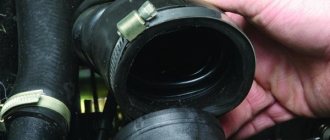
Troubleshooting (misfire) may be related to the coil tips. In this case, they must be replaced immediately. Otherwise, it may even break through the control transistor or short-circuit the secondary winding.
The malfunction of the coil itself is often associated with its primary winding, which requires its replacement. In this case, it is necessary to ensure complete insulation of the wires.
Catalog numbers
These important components of the Toyota ignition system (like all others) have a ten-digit catalog number. The first five are the same for all coils - 90919, the next five (usually written with a dash) are different, for example, 02117, 02163, 02234, 02259, 02265, etc.
Considering the important role that this module plays, it would be correct not to experiment with installing suitable coils on the machine, but to install only the one recommended by the manufacturer.
All errors TOYOTA 4RUNNER, ALLEX, ALLION, ALPHARD, ALTEZZA, ARISTO, AURION, AURIS, AVALON, AVENSIS, AYGO, BB, BELTA, BLADE, BREVIS, CALDINA, CAMI, CAMRY, CELICA, CELSIOR, CENTURY, COROLLA, ECHO, ESTIMA , FJ CRUISER, FORTUNER, FUNCARGO, GT86, HARRIER, HIACE, HIGHLANDER, HILUX, INNOVA, IPSUM, iQ, ISIS, IST, KLUGER HYBRID, KLUGER V, LAND CRUISER, LAND CRUISER PRADO, MARK, MARK X, MATRIX, MR 2 , NADIA, NOAH, OPA, PASSO, PLATZ, PREMIO, PREVIA, PRIUS, PROBOX, PROGRES, RACTIS, RAUM, RAV4, RUSH, SAI, SEQUOIA, SIENNA, SIENTA, SOLARA, TACOMA, TUNDRA, URBAN CRUISER, VANGUARD, VELLFIRE, VENZA, VERSO, VITZ, VOLTZ, VOXY, WILL CYPHA, WILL VS, WINDOM, WISH, YARIS.
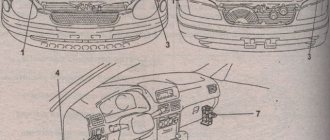
Location and types of diagnostic connectors
Cars of the Japanese manufacturer Toyota were equipped with two types of connectors that allow diagnostics - DLC1 and DLC2. More modern models use a DLC3 connector (standard OBD-II).
DLC1 is made in the form of a rectangle located on the left side of the engine compartment (in most cars of this brand). The plastic cover of this connector is marked Diagnostic.
Toyota errors can manifest themselves as follows:
- If a malfunction is detected in the engine, the Check Engine indicator on the instrument panel will light up.
- But if a breakdown occurs in the automatic transmission, the O\D OFF indicator will light up on the panel.
- The SRS light indicates a malfunction in the passive safety system (airbags, seat belt pretensioners).
- The ABS indicator lights up if there are errors in the operation of the anti-lock braking system.
- If the traction control system fails, the TRC lamp on the instrument panel will light up.
The DLC2 diagnostic connector in almost all cars of this manufacturer is located under the dashboard on the driver's side. Outwardly it differs from the first one. One of the features of this connector is the ability to diagnose a car on the go.
In earlier Toyota models, the diagnostic connector is located in the engine compartment. Typically, it is round in shape and yellow in color. It can often be found near the battery.
Modern scanners
Reading Corolla fault codes with scanners not only simplifies self-monitoring, but also makes it more informative. Today, manufacturers of diagnostic car scanners supply the market with a wide range of them, differing both in functionality and price. On the one hand, such a market is capable of satisfying the needs of various segments of consumers, but on the other hand, it creates certain difficulties, since it requires some special knowledge when purchasing. Here we will only indicate the main types of diagnostic equipment, as well as its purpose. And this will not be a bad guideline for choosing the right scanner. Based on functionality, scanners are distinguished between dealer, brand and multi-brand.
Corolla robot error codes
Dealer scanners are produced by automakers or their contractors, usually for a specific car brand. They have a wide range of functionality and are intended for professional use, and the price can reach several thousand dollars.
The group of brand scanners is also intended for professional use. They have functionality similar to that of the dealer, but more modest. The price of branded scanners ranges from several hundred to a thousand dollars.
Fault codes for automatic transmission and ABS Corolla
Multi-brand scanners are most widespread among motorists. They are easy to use and provide sufficient information for most situations. Scanners of this group are unified for several car brands. Therefore, when purchasing, you need to check their ability to read Corolla error codes.
Error codes for Corolla with VSC system
Self-diagnosis - step-by-step instructions
Professional car diagnostics at a specialized service center is not cheap. In addition, many car owners simply do not have the opportunity to use such services, since they live far outside large cities, and they have no desire to turn to “garage” specialists.
In such cases, self-diagnosis methods come to the rescue. Only basic skills are needed, so even beginners can figure it out. For example, to check engine operation, the procedure is performed in the following order:
- Open the hood and find the DLC1 connector with a plastic cover (look for the inscription Diagnostic). Open or unscrew the cover and find the contact markings on the back side. Use a paper clip or a piece of wire to connect terminals TE1 and E1.
If your car uses a DLC3 connector, you need to close contacts TC and CG.
- Turn on the ignition and watch the instrument panel indicators. The Check Engine and O\D lights should blink. If they light up and go out at intervals of about 0.5 seconds 11 times or more, no errors have been detected in the operation of the engine and automatic transmission. On some cars, the Check Engine light may light up and go out repeatedly with an interval of 4.5 seconds, this is also a sign of normal operation of all internal combustion engine systems.
- If you find that the indicator is reporting errors, you need to move on to the next section.
Proper diagnostics
Continuation of 1.3 Corolla engine error codes
The Toyota Corolla diagnostic system consists of sensors that record the physical parameters of components, an electronic control unit (ECU), a program for this unit, as well as a fault indication system.
Initially, the manufacturer entered the reference values of the state parameters of the vehicle components into the ECU memory. During operation, the sensors record the actual values of these parameters and then send them to the electronic control unit. The Corolla ECU compares the received actual parameters with the reference values and, if they do not match, writes a code into memory. After this, the control unit sends an error code to the Toyota Corolla “CHECK” indicator light. When the fault is corrected, the error signal disappears. In addition, it is possible to force the reading of fault codes with or without a scanner.
Malfunctions of the 1.3 Corolla engine
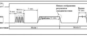
On the light indicator, error codes are visualized by the number of light signals, as well as the combination of their length and pauses between them. Toyota uses two types of light codes: 09 and 10. 09 is a two-digit code. This means that it starts with the number 11 and ends with the number 99. The duration of the glow - pause is 0.5 seconds. The pause between tens and ones is 1.5 seconds, the pause between ciphers is 2.5 seconds, and between a series of ciphers is 4.5 seconds. For example, two glares with a pause of 0.5 seconds plus one glare after 1.5 seconds corresponds to 21 error codes.
Code 10 is a unique cipher. In it, the number of light pulses corresponds to the fault error code. Just like in the previous cipher, the duration of the lights - pauses is 0.5 seconds. In this case, the pause between ciphers is 2.5 seconds, the pause between a series of ciphers is 4.5 seconds. 12 glares in 0.5 seconds correspond to the 12th fault code error.
Engine fault codes 1.4 Corolla
During the operation of the Corolla, the need arises for forced diagnostics of individual components of the car. For this, three blocks of diagnostic connectors (DLC - DataLinkConnector) are installed: DLC 1, DLC 2, DLC 3. The DLC 1 connectors are assembled in a diagnostic box labeled “Diagnostic”, which is located under the hood at the rear wall of the engine compartment. Connectors DLC 2, DLC 3 are located inside the car on the driver's side. DLC 2 connectors are installed under the panel, and DLC 3 under the front door. The DLC 2 block is used to read information with special scanners.
Error codes for the 1.4 King engine
The DLC3 unit has very limited use; it can be found on Corollas with a robotic gearbox.
It should be noted that the location of the scanning blocks may vary slightly under the hood or in the cabin, depending on the make and year of manufacture of the car.
DLC 1 consists of 20 connectors designed for engine and transmission self-diagnosis.
1.6 Corolla engine fault codes
To open the lid of the box, just pull the visible petal. The standard diagnostic procedure is carried out using a scanner. But in the absence of a scanner, the necessary information at home can also be obtained without it. To perform this procedure, perform the following diagnostic steps:
Corolla 1.6 engine malfunctions
If it blinks more than eleven times with an amplitude of half a second, then this indicates the absence of errors in the ECU memory, as well as the serviceability of the machine. This encoding corresponds to the 09 cipher. If “CHECK” blinks with an amplitude of four and a half seconds, it means that the car uses code 10 and it is also working.
Engine 1.6 Fault codes
And if the signals are different, it is necessary to read the code, determine the type of malfunction from the code and, depending on this, take further action. Self-monitoring of other nodes is carried out in a similar way. Only blocks of components and pairs of connectors, as well as indicators on the instrument panel, can be changed.
Decoding error codes for Toyota gasoline engines
The codes are read by the number of flashes of the Check Engine light with the ignition on and closed contacts TE1-E1 of the diagnostic connector DLC1 in the engine compartment or TC-CG in DLC3 under the front panel.
Error code and explanation:
- 12 / P0335 – incorrect signal from the crankshaft position sensor (CPS);
- 14 / P1300 or P1315 – ignition system error – coil 1 or 4;
- 15 / P1305 or P1310 – ignition system error – coil 2 or 3;
- 16 – malfunctions in the automatic transmission control system;
- 18 / P1346 – malfunction of the engine variable valve timing system (VVT-i);
- 19 / P1120 / P1121 – incorrect signal from the accelerator pedal position sensor;
- 21/P0135 – lambda probe malfunction;
- 22 / P0115 – malfunction of the coolant temperature sensor;
- 24 / P0110 – incorrect data from the intake air temperature sensor;
- 25 / P0171 – lambda probe – lean mixture;
- 27 – lambda probe No. 2;
- 31 / P0105 / P0106 – malfunction of the absolute pressure sensor;
- 34 – defect in the turbocharging system;
- 35 – malfunction of the turbine pressure sensor;
- 36 / P1105 – malfunction of the pressure sensor in the combustion chamber of cylinder No. 1 (CPS);
- 39 / P1656 – malfunction in the VVT-i system;
- 41 / P0120 / P0121 – incorrect signal from the throttle position sensor (TPS);
- 42 / P0500 – speed sensor malfunction;
- 43 – no starter signal;
- 47 – incorrect data from the additional throttle valve position sensor;
- 49 / P0190 / P0191 – incorrect data from the fuel pressure sensor;
- 52 / P0325 – knock sensor error;
- 53 – incorrect knock sensor signal;
- 55 – error of the second knock sensor;
- 59 / P1349 – incorrect signal from the variable valve timing system;
- 71 / P0401 / P0403 – malfunction of the exhaust gas recirculation (EGR) system;
- 97 / P1215 – problems with fuel injectors.
Deciphering fault codes for Toyota Corolla
Standard errors are displayed on the on-board computer display. For older modifications, the display on the instrument panel in the form of corresponding icons is relevant. Here you can see breakdowns only when connecting an external scanner.
The following are common codes found on most vehicle assemblies.
Error C0210
The rear right wheel speed sensor is not working correctly. Check wiring and sensor.
C0215 - code
Same for the rear left sensor.
C1241 - malfunction
A DTC error is recorded if the voltage at the power source is below the specified limit.
U0100 - code
The contact on the bus between the engine control unit and the central diagnostic system is broken. It is necessary to ring the bus for breaks or oxidation of contacts.
U0129 - Corolla code
Loss of communication with the ECU via the CAN bus. The repair steps are the same as above.
B1421 - malfunction
Solar activity sensor on the driver's side. Perhaps the controller is simply dirty or its contact group has come loose.
B1423 - error
The pressure sensor circuit is broken or damaged. Check that the device is connected correctly. If the module functions correctly, diagnose the monitored device.
B1821 - Corolla error
Open circuit for controlling the airbag squib igniter. Diagnostics of highways is needed.
B279a - malfunction
An increased signal is constantly visible in the communication line of the anti-theft system. It is possible that the control circuits are shorted to the positive wire.
B2799 - Corolla malfunction
Loss of communication between the engine control unit and the immobilizer module. Here there is a break in the contact group or oxidation on the pads. In rare cases, the cause is connected parts of systems.
Error 12 Corolla Ceres
The crankshaft position sensor is supplying incorrect data to the ECU.
Code 14
There are problems in the ignition coils. The presence of faults in the wiring and contact groups is taken into account.
Error 15
There is a loss of contact on coil 2 of the ignition system.
Code 21 climate control
The malfunction does not indicate a breakdown of oxygen sensor No. 1. On the latest versions of the car, the system indicates a breakdown in the air conditioning system.
Error 22
The coolant temperature sensor is transmitting incorrect data. A more thorough diagnosis of the node is needed. Usually contact is lost on the wiring.
Code 24
The intake manifold air temperature sensor is not working properly. A similar problem occurs on the AE100 type model.
Error 25
Excessively lean fuel mixture. Check throttle settings and line leaks.
Code 26
The opposite value is an over-enriched mixture at the inlet to the manifold. Look at the air route. The filter is usually clogged.
Code 31
The intake manifold absolute pressure sensor is faulty. It may also indicate a wiring problem.
32 - Corolla error
The left front wheel speed sensor of the ABS module is faulty. It is necessary to check the lines and sensor for defects.
ABS fault 33
On bodies 124 and 150, it indicates a breakdown of the front right ABS sensor. The control circuits also need to be checked.
Error 34 A
Same for the rear left wheel.
Code 35
The same for the rear right wheel.
36 - breakdown
Complete break in the wheel rotation sensor circuit.
Code 41
The throttle position sensor is not working properly.
42 - malfunction
The signal from the speed sensor does not reach the ECU.
Code 51
Open circuit in the ABS pump power supply.
Error 52 Corolla Spasio
On gasoline models after 97 years of production, indicates a malfunction of the knock sensor. This often happens after refueling with low-quality fuel.
Code 93
Misfires to protect the catalyst. Here you need to look for the cause in the ignition system.
Error P0011
Malfunctions in the valve timing system. It is necessary to check the DPKV and its wiring for damage.
Code P0012
Camshaft clutch lag. Similar problem as in the paragraph above.
Error P0016
Synchronization between DPKV and DPRV is broken. Look for a problem in the control unit.
P0136 - Corolla malfunction
DK1 is broken or something has flown into the exhaust line.
P0171 - Corolla malfunction
Loss of tightness of the intake tract, usually this occurs when driving on gas if the installation is configured incorrectly.
P0172 - error
The fuel mixture supply system is not working properly. Gasoline does not burn completely; more air needs to be supplied.
Code P0340
DPRV control circuit malfunction.
Code P0351
Failure 0351 indicates a problem with the ignition coil of the first cylinder.
Code P0352
Likewise for the second cylinder.
P0353 - breakdown
Third cylinder - ignition coil is not functioning correctly.
Code P0354
The same for the fourth working chamber.
Error P0420 Corolla Verso
Catalyst efficiency is below the specified threshold. The insert needs to be replaced. Also, many drivers cut it out and change the firmware to a simpler one.
P0500 - error
The vehicle speed sensor is not working properly. In a separate case, there are problems with the wiring.
Breakdown P0505
Incorrect operation of the intake air valve. The module is stuck in the closed or open position.
P0741 - malfunction
The torque converter clutch lock-up valve is stuck. Check valve and control circuits.
P0806 - code
The clutch position sensor is transmitting a signal out of range.
P0810 - error Toyota Corolla robot
There is a malfunction in the XY axis shift lever control circuit. The transmission periodically flies into neutral. This happens in winter. If there is a breakdown of 0810, it is recommended to contact specialized specialists.
P0812 - error
Gear selection or clutch release actuator – modules need to be checked. Sensors are also checked.
Code P0820
Internal failure of volatile memory. Requires diagnostics at a service station.
Error P0900
Malfunction 0900 indicates a break in the clutch control line.
Code P0910
The gear selection rocker actuator is not initialized correctly.
Robot error 0915
The gearshift sensor has failed.
Breakdown of P1300
Typical malfunction of the ignition coil control circuit of cylinder 1.
P1349 - code
The VVT-I valve is not working correctly. Replace the entire device.
Error P1604
Too many unsuccessful attempts have been made to start the engine. The reason is the use of low-quality fuel, the battery is critically discharged.
P1656 - code
Short circuit in the VVT-I valve control circuit.
Corolla Axio: error P2118
Code 2118 indicates that the throttle valve actuator is out of range.
P2237 - code
Breakage of the positive line DK1. Problem 2237 indicates that the system is not working properly.
Code P2196 Corolla
A breakdown indicates a problem in the first lambda. The sensor should be checked.
PS Corolla Error
The power steering system is not working correctly.
Charging system - malfunction
Look for a problem in the charging relay or generator wiring.
Error: Check engine
Perform detailed diagnostics of on-board equipment. The car may show a lean mixture, which also affects the appearance of "Jackie Chan". In any situation you need to connect a scanner.
Error - check the brakes
Here, an insufficient amount of fluid in the expansion tank consistently appears. Worn brake pads may also show signs of wear.
Corolla airbag error
The elements in the machine are highly reliable. In this case, problems may arise related to the functioning of the squib igniter.
Bugs box robot
There are usually no problems with the robot. Here breakdowns may occur due to lack of necessary maintenance or mechanical damage.
Oil pressure errors
Check the lubricant level in the crankcase. If everything is in order, diagnose the oil pump or replace the lubricant with one suitable for this engine.
Initialization faults
You will need specialist help. If there are initialization problems, self-repair will be ineffective.
Error codes for Toyota diesel engines
Malfunctions and explanation:
- 12 – incorrect DPKV signal;
- 13 – problem with the speed sensor;
- 14 – malfunction of the valve for changing the injection advance angle;
- 15 – breakdown of the throttle servo drive;
- 17 – incorrect signal from the control unit;
- 18 – problems in the operation of the electromagnetic bypass valve;
- 19 – malfunction of the accelerator pedal position sensor;
- 22 – incorrect signal from the liquid temperature sensor in the internal combustion engine cooling system;
- 24 – malfunction of the intake air temperature sensor;
- 35 – failure of the turbocharger pressure sensor;
- 39 – incorrect signal from the fuel temperature sensor;
- 42 – incorrect data from the speed sensor;
- 96 – failure of the EGR valve position sensor.
Toyota Corolla error codes
There is some experience with the most common Corolla error codes that can help resolve the problem. Often the CC registers code p0810 for the Toyota Corolla 2006 - 2009 gearbox, which indicates a general clutch position control error. The reasons may be caused by a breakdown of the actuator, TCM or travel sensor.
VSC and power steering errors
Trouble code p0900 in Corolla specifically indicates damage to the clutch actuator circuit. The reasons for the appearance of the p0900 signal are an open circuit in the wiring or failure of the Corolla clutch actuator motor.
Air conditioning fault codes
A series of similar errors p0351, p0354, p0352, p0353 Toyota Corolla indicates defects in the low voltage circuit of the ignition coils. These codes occur due to an open or short circuit in the IGF1 and IGT circuit between the ignition coils (1-4) and the ECM. To eliminate them, first the circuit is tested for a short circuit, then coils 1–4 are checked, if the errors do not disappear, the ECM is replaced.
Relatively often, the Corolla has a speed signal malfunction with code C1541. The error code may be caused by abnormalities in the speed sensor circuit, skid control ECU, CAN communication system, or power steering ECU.
Air conditioner errors
Code P0500 speed sensor signal on Toyota means that the automatic transmission engine control unit does not receive data about the speed of the vehicle. With this error, the Corolla goes into emergency mode. The reasons for the appearance of the code may be an open or short circuit in the speed signal circuit, a malfunction on the Corolla instrument panel, the skid control ECU, or the Corolla speed sensor.
Toyota automatic transmission fault codes
To read the codes, you need to count the number of times the O/D OFF light comes on with the ignition on and terminals TE1-E1 in the DLC1 connector (in the engine compartment) or TC-CG in the DLC3 connector (in the passenger compartment) closed. Check that upshifting is not prohibited (the O/D OFF indicator should not be illuminated).
Codes and decryption:
- 11 – all indicators are normal;
- 37 / P1705 – malfunction of the transmission input shaft speed sensor;
- 38 – incorrect signal from the transmission fluid temperature sensor;
- 42 / P0500 – speed sensor or output shaft speed sensor;
- 44 – failure of the rear output shaft speed sensor or speed sensor;
- 46 / P1765 – failure of the hydraulic accumulator pressure control solenoid;
- 61 – malfunction of the front output shaft speed sensor or speed sensor;
- 62 / P0753 – problems with the first solenoid;
- 63 / P0758 – problems with the second solenoid;
- 64 / P0773 – malfunction of the torque converter locking clutch solenoid;
- 67 – incorrect readings of the transmission input shaft speed sensor;
- 68 – breakdown of the torque converter locking clutch solenoid;
- 73 – malfunction of the center differential locking clutch solenoid.
ABS system errors
Reading faults (DLC1 connector):
- turn on the ignition;
- install a jumper between contacts TC and E1;
- remove the jumper from contacts WA and WB;
- after 4 seconds, count the number of times the warning light lights up;
- remove the jumper from the TC and E1 contacts;
- install a jumper on contacts WA and WB.
Error reset (DLC1 connector):
- turn on the ignition;
- install a jumper between contacts TC and E1;
- press the brake pedal at least 8 times in a three-second interval;
- the warning light should flash twice per second (confirmation of a normally operating system);
- turn off the ignition;
- remove the jumper from the TC and E1 contacts;
- Make sure that the ABS light on the instrument panel does not light up.
Reading faults (DLC3 connector):
- install a jumper between the TC and CG contacts;
- turn on the ignition;
- after 4 seconds, count the number of times the warning light lights up;
- remove the jumper from the TC and CG contacts.
Error reset (DLC3 connector):
- install a jumper between the TC and CG contacts;
- turn on the ignition;
- press the brake pedal at least 8 times in a three-second interval;
- the indicator should blink twice per second (confirmation of system health);
- remove the jumper from the TC and CG contacts.
Errors and explanation:
- 11 – damage to the solenoid valve relay circuit;
- 12 – short circuit in the valve relay circuit;
- 13 – damage to the electric pump relay circuit;
- 14 – short circuit in the pump relay circuit;
- 21/22/23/24 – break or short circuit in the solenoid valve of one of the wheels;
- 31/32/33/34 – incorrect signal from the wheel speed sensor (FP - front right / PL - front left / ZP - rear right / ZL - rear left);
- 41 – unacceptable battery voltage;
- 43/44 – damage to the deceleration sensor circuit;
- 49 – damage to the brake light switch circuit;
- 51 – damage or short circuit of the pump power supply circuit;
- 71/72/73/74 – incorrect signal from the wheel rotation sensor (PP/PL/ZP/ZL, respectively);
- 75/76/77/78 – error in correcting the signal from the wheel speed sensor (PP/PL/ZP/ZL, respectively);
- 79 – failure of the deceleration sensor;
- 98 / C1200 – failure of the brake booster vacuum sensor.
Error codes for the SRS security system in Toyota cars
The codes are read with the ignition on based on the number of times the SRS lamp lights up. In connector DLC1, contacts TC and E1 must be closed, and in DLC3, a jumper is installed between pins TC and CG.
Error codes must be erased when the ignition is turned off. If the codes are stored in memory, follow these steps:
- connect two wires to pins TC and AB;
- turn on the ignition and wait at least 6 seconds;
- in turn, 1 time per second, close contacts TC and AB to ground with an interval between closures of no more than 0.2 seconds;
- after the third circuit, the TC light on the panel should flash quickly, which confirms that the codes have been deleted from the memory.
- 11/12/13/14 – short circuit or break in the driver airbag igniter circuit;
- 15/16 – short circuit or open circuit in the front SRS sensor circuit;
- 31 – failure of the security system control unit;
- 51/52/53/51 – short circuit or open circuit of the passenger airbag igniter;
- 61/62/63/64 – short circuit or open circuit of the driver’s seat belt pretensioner;
- 71/72/73/74 – short circuit or break in the passenger seat belt pretensioner circuit.
Electric power steering Self-diagnosis (how to read fault codes) 1. Check the “P/S” indicator. Turn on the ignition and make sure that the indicator lights up and goes out after 2 seconds. 2. Reading fault codes (without using a scanner). a) Jumper the terminals “TC” and “CG” of the DLC3 connector.
b) Turn on the ignition. c) Read the fault codes by the number of flashes of the “P/S” indicator. Notes: — If there are no faults, the indicator blinks continuously at a frequency of 2 times per second.
— If there is a malfunction, after a pause of 4 seconds, the codes begin to be displayed. — The indicator flashes 1 time per second. The first sequence of flashes corresponds to the first number of the diagnostic code, consisting of two numbers. After a pause of 1.5 seconds, a second sequence of flashes is displayed, corresponding to the second number of the code. — If there are two or more fault codes, the output between them is set to an interval of 2.5 seconds. The display will start from the lowest number and continue upward. — After a pause of 4 seconds, the codes are displayed again.
3. Erasing fault codes (without using a scanner). a) Jumper the “TS” and “CG” pins of the DLC3 connector. b) Turn on the ignition. c) Within 8 seconds, disconnect and connect the jumper to the “CG” terminal at least 4 times. d) Make sure that the normal code is displayed. e) Remove the jumper.
4. Check in test mode (without using a scanner). a) Jumper the “TS” and “CG” pins of the DLC3 connector. b) Turn on the ignition. c) Make sure that the normal code is displayed or read the fault codes. d) Remove the jumper. e) Turn the ignition off and on. Note: Codes 71 and 73 will be displayed in test mode even if the sensors are working. Zero point calibration The installation is performed in the following cases: — When removing the steering column or steering rack assembly. — When replacing the EUR control unit. 1. Set the steering wheel and front wheels to the straight ahead position. 2. Perform zero point initialization. Note: when replacing the EUR control unit, this operation is not performed.
When using a scanner a) Stop the car (front wheels in straight ahead position). b) Connect the scanner to the DLC3 connector and initialize.
Without using a scanner a) Stop the car. b) Jumper the “TS” and “CG” pins of the DLC3 connector. c) Jumper the “TC” and “CG” pins of the DLC3 connector. d) Within 20 seconds, disconnect and connect the jumper to the “TC” terminal 20 times. e) Turn off the ignition. h) Perform zero point calibration.
When using a scanner
Note: Do not turn the steering wheel a) Stop the vehicle (front wheels in straight ahead position). b) Perform zero point calibration. c) After calibration is completed, the “P/S” indicator should blink at a frequency of 2 times per second.
Without using a scanner a) Jumper the “TS” and “CG” terminals of the DLC3 connector and turn on the ignition. b) After 8-13 seconds, the “P/S” indicator should start flashing at a frequency of 2 times per second. c) Remove the jumper. d) Make sure there are no fault codes.
Table of diagnostic trouble codes for the power steering system
SAE code / Code
| System | Possible fault location | |
| S1511/11 | Torque sensor (1) - malfunction |
|
| S1512/12 | Torque sensor (2) - malfunction |
|
| S1513/13 | Torque sensor (3) - malfunction |
|
| S1514/14 | Torque sensor - malfunction in the power circuit |
|
| S1515/15 | Torque sensor - zero point calibration failed |
|
| S1516/16 | Torque sensor - zero point calibration not completed |
|
| S1521/21 | Electric motor - malfunction (current higher than permissible) |
|
| S1523/23 | Electric motor - malfunction (current deviations) |
|
| S1524/24 | Electric motor - malfunction (incorrect voltage at motor terminals) |
|
| S1531/31 | EUR control unit - malfunction (control module) |
|
| S1532/32 | EUR control unit - malfunction |
|
| S1533/33 | EUR control unit - malfunction (control unit board temperature sensor) |
|
| S1541/41 | Speed sensor - malfunction |
|
| S1542/42 | Speed sensor - malfunction |
|
| C1544/44 | Engine speed signal - malfunction |
|
| C1545/45 | Engine speed signal - malfunction |
|
| C1551/51 | Power Supply - Circuit Failure |
|
| C1552/52 | Power supply voltage of the EUR control unit |
|
| C1554/54 | Power Supply Relay - Circuit Fault |
|
| C1555/55 | Motor Relay - Circuit Fault |
|
Errors in the 4WS system
To read errors, you need to count the number of flashes of the 4WS lamp. In this case, the ignition must be turned on, and contacts TC and E1 in connector DLC1 must be closed.
Decoding the main errors:
- 11 – failure of the 4WS ECU;
- 12 – breakdown of the main electric motor of the rear steering mechanism;
- 13 – failure of the steering gear control drive;
- 21 – short circuit in the main electric motor circuit;
- 22 – open circuit in the power supply system of the main electric motor;
- 23 – malfunction of the main electric motor blocking;
- 24 – breakdown of the main electric motor;
- 31 – damage to the reverse electric motor system;
- 32 – breakdown in the operation of the reverse electric motor;
- 41 – failure of the front left wheel speed sensor;
- 42 – 4WS system sensor failure;
- 43 – incorrect signal from the 4WS system sensor.
Help from our specialists
Dear users of the Autofakty project! Unfortunately, it is extremely difficult to list all Toyota error codes and their detailed decoding. Therefore, if you were unable to find the answer to your question in our article, write to us in the comments at the bottom of the article. Please indicate the year of manufacture, car model, engine and gearbox type, as well as the error code for which you are looking for decoding. We will do our best to find an answer to your question as quickly as possible. Stay with us!
Hello people! I know that now you will all start kicking me in the stomach and sending me to a search engine. But I was already there and no matter how hard I tried I couldn’t find any error codes. Maybe if it’s not difficult for anyone to post a link to error code number 14.
Added after 1 hour 17 minutes 25 seconds:
Mmm, everyone is kind of sluggish. Guys, I really need it. Someone help me with the answer.
Falcon, codes for the barrel!
Added after 16 minutes 15 seconds:
In short, the ignition system! 20 times in a row The IGF signal does not appear to the ECU at a rotation speed of less than 3000. Reason: 1-break or short circuit in the circuits of the IGF,IGT switch, 2-switch, 3-ECU.
@Shaved
Falcon, codes for the barrel!
Added after 16 minutes 15 seconds:
In short, the ignition system! 20 times in a row The IGF signal does not appear to the ECU at a rotation speed of less than 3000. Reason: 1-break or short circuit in the circuits of the IGF,IGT switch, 2-switch, 3-ECU.
Shaved What's the problem? Does not start?
This code means that when the starter rotates (or when the computer thinks that the starter is rotating), the computer does not receive a signal from the ignition coil control unit.
Somehow the retractor wire came off the starter, I turned the key, the computer thought that the starter was turning the engine and wondered why there was no signal from the crankshaft speed sensor. As a result, I found and fixed the problem, forgot about it and went about my business, and a month later, after doing a self-diagnosis, I discovered code 13 in my memory.
@Shaved
And the problem guys is this: Completely out of the blue, while driving I felt that the engine began to openly stall. More like five to be exact. I was surprised, because I had recently changed the spark plugs, and since I was driving slowly around the yard, I turned on N and hit the slipper a couple of times, it seemed like he had screwed up. Then I went out onto the highway, accelerated to 90, drove for a while, it started to shake again, but it really did, because it already had a sound when I stopped, like a tractor, and it didn’t shake sourly. At the same time, the check light came on, and the turn off light came on, for some reason it also came on. After standing like that for some time and revving up, they went out, the engine also seemed to work. I drove on (I was not at home, I was driving from the village), then while driving, everything started again, the engine light came on, no luck. When you press the floor, the traction completely disappears and the engine almost stalls. then everything returns to normal again, it starts to drive normally, then after a while the light goes out. I've put it on hold for now and won't drive it again until I figure it out. Today I did a self-diagnosis, it showed error number 14, I have no codes. I couldn't find it in the search engine. Here’s another thing: several times I left the car overnight in the yard, and since my signaling system was broken, I pulled out the EFI relay overnight just in case. Repeatedly. Could something be causing this?
Sincerely . Shaved.
Added after 3 hours 17 minutes 35 seconds:
Damn, does no one really know what error number 14 means?
there is one in the FAQ. Plus this week we were discussing code 14. Why rub the same thing 10 times? I wish I could find it. If you haven’t found it, then you don’t really need it.
Added after 3 minutes 25 seconds:
Yes, everyone knows.. and they answered you once already.. how much do you need? ))
PS First of all, you need to decide on the car. or Tourer V or JZX91. otherwise these are slightly different engines.
@Shaved
So, in order:
2. Would you like to find it? You know, not everyone apparently knows how to use the notorious FAK about which I know nothing.
3. Answered. But there are a lot of abbreviations, and I didn’t understand what I wrote about.
4. If everyone knows, what is so difficult to repeat? I haven’t visited this site for half a year, and now I’ve noticed that the more people there are, the worse it gets. No one had ever screwed up like this before. Maybe ask the Honda drivers, maybe they will be kinder and answer.
5. Engine 1GZ-GTE body JZX-91, what’s unclear here?
the very first topic.
I didn't understand. Do you want to repair it yourself or will you go to a service station? and Phantom wrote to you without abbreviations.
not difficult. the control unit does not see the signal from the coil/coils. You can at least ask Kalinovodov. )
Shaved To be honest, I don’t fall for it, but they already answered.
You better tell me what YOU don’t understand from
@Shaved
I think it’s worth starting by inspecting all the *chips* of the wiring. In general, since you don’t understand anything, it’s better (and perhaps cheaper in the future) to contact a service station.
@ Shaved @ Shaved @ Shaved
this is the name of the pins on the ECU connector
Added after 1 minute 35 seconds:
@Shaved
You're confusing, there's a coil for each spark plug. And about the computer. Damn, if you check the above connectors, as I understand it, you need to remove the panels in the cabin? The computer is hidden under the panel.
Added after 5 minutes 19 seconds:
And again, what Phantom wrote to me is a completely different opera. What does the starter have to do with it? And he talks about the 13th error!
I gave error 13 just as an example. So to speak, I developed the topic based on my life experience. By this I wanted to say that a fault code does not always indicate exactly the fault it indicates, and its appearance can be triggered by a simple coincidence or a combination of other faults. At that time, I did not know the whole history of your problem (by the way, if I were you, I would have started the first post with this, so that those responding would have full control of the situation). Considering the details you provided, you can forget about my story about error 13 - this is definitely not your case.
Now directly in your case. The decoding of the code says verbatim exactly what Zenya wrote:
I looked at the decoding for the 80th body, there is a slightly different wording. With your engine, as far as I understand, something like the following happened: at some point the computer, for some reason, stopped seeing one or more ignition coils, at which time the cylinder (cylinders) served by this coil (coils) did not work (did not work) , then the signal from the coils appeared and the cylinders started working, but the code was already written into memory, then the signal disappeared again. All this is very similar to a weak contact in the connector or a break in some wire. To begin with, I would try to remove the connectors from the coils, clean everything, put them back and check. If it doesn't help, climb further. The crankshaft revolutions here play a role not so much for a person as for a computer: it’s just that at high revolutions the error would not have been recorded or would have been recorded, but something else. And further. If the electronics on the 1JZ-GTE in the 90th body are arranged in the same way as in the 80th, then the computer has 7 IGF pins: IGF, IGF1, IGF2, IGF3, IGF4, IGF5, IGF6.
| Damn, it was easier with a three-liter brand. At least there was a distributor. And here I don’t even know where to go after the armored wires. |
The ignition coils on the 1JZ-GTE are assembled with spark plug holders and look like “knobs” in their upper part. Chips with thin wires are connected to these “knobs”. Accordingly, each spark plug has its own coil. Therefore, there is no need for a distributor and high-voltage wires: there is simply no need to distribute high voltage across the spark plugs and supply it from the coil to the distributor, from the distributor to the spark plugs; it is “born” directly above the spark plug.
1. When the car moves at a speed of more than 10 km/h, an open or short circuit occurs in the sensor circuit for 1 s or more.
2. There have been at least 7 short-term interruptions of the wheel sensor signal, the operation of which is disrupted.
3. Open circuit in the sensor circuit for more than 0.5 s.
— Speed sensor.
— Wiring and connector of the speed sensor
— Speed sensor rotor.
— ABS control unit.
Front left wheel speed sensor circuit malfunction
Malfunction of the rear right wheel speed sensor
Malfunction of the rear left wheel speed sensor
Malfunction
Check conditions
Checked elements
Open or short circuit in the front right wheel solenoid valve circuit
Open circuit in the sensor circuit for more than 0.5 s.
1. Solenoid valve.
2. Pressure modulator.
Open or short circuit in the front left wheel solenoid valve circuit
Open or short circuit in the rear wheel solenoid valve circuit
Open circuit in the electric pump relay circuit
When one of the following conditions is met:
— Conditions are met for more than 0.2 s:
— The voltage at pin “IG1” is within 10 -16 V.
— Relay contacts are open for more than 0.2 s (relay in “ON” position).
— Conditions are met for more than 0.2 s:
— The voltage at pin “IG1” is less than 10 V.
— The relay contacts are constantly open (relay in the “ON” position).
— Pressure modulator (electric pump relay).
— Electric pump relay circuit.
Short circuit to power in the electric pump relay circuit
When switching the relay to the "OFF" position, the contacts remain closed for 4 s or more
Open circuit in relay
When one of the following conditions is met:
1. Conditions are met for more than 0.2 s:
— The voltage at pin “IG1” is within 10 -16 V.
— Relay contacts are open for more than 0.2 s (relay in “ON” position).
2. Conditions are met for more than 0.2 s:
— The voltage at pin “IG1” is less than 10 V.
— The relay contacts are constantly open (relay in the “ON” position).
— Pressure modulator (solenoid valve).
— Solenoid valve relay circuit.
Short circuit to power in the solenoid valve relay circuit
The relay is in the “OFF” position, immediately after turning on the ignition, the contacts remain closed for 0.2 s or more.
Foreign material between the rotor and the front right wheel speed sensor
When the vehicle is moving at a speed of more than 20 km/h, the signal is distorted for 5 seconds or more.
— Speed sensor and rotor.
— ABS control unit.
Foreign material between the rotor and the front left wheel speed sensor
Foreign material on the rear right wheel speed sensor tip
Foreign material in contact with rear left wheel speed sensor tip
Battery voltage is too high or too low
When one of the following conditions is met:
1. Conditions are met for more than 10 s:
— The car is moving at a speed of more than 10 km/h.
— The voltage at pin “IG1” is less than 10 V.
2. Conditions are met for more than 0.2 s:
— The solenoid valve relay is constantly in the “ON” position.
— Relay contacts are open.
— The voltage at pin “IG1” is less than 10 V.
Deceleration sensor malfunction (constant signal)
A car moves at a speed of 30 km/h and stops. There is no change in the deceleration sensor signal more than 16 times.
Deceleration sensor and circuit
Malfunction
Open or short circuit in the deceleration sensor circuit
When one of the following conditions is met:
1. An error is detected in the signal from the deceleration sensor more than 7 times.
2. The operating voltage of the sensor is not in the range of 4.25 - 5.25 V.
3. The deceleration value calculated from the GL1 signal for 1.2 s is not in the range of -1.5 -1.5 G.
— Sensor and deceleration sensor circuit
Incorrect deceleration sensor output
The difference between the acceleration and deceleration values calculated from the deceleration sensor and vehicle speed sensor signals exceeds 0.35G for 60 seconds or more.
Differential lock switch - malfunction
The vehicle is moving at a speed of more than 50 km/h, the differential lock switch is set from the “OFF” to “ON” position for 3 seconds or more.
— Switch or circuit of switch and differential lock.
— ABS control unit.
Open in the brake light switch circuit
— The voltage at pin “IG1” is within 10 -16 V, there is an open circuit in the brake light switch circuit for 0.3 s or more.
— Brake light switch or circuit.
Open circuit in the electric pump power supply circuit
When one of the following conditions is met:
— The ABS electric pump is faulty.
— An open circuit in the power supply circuit of the electric pump for 2 s or more.
2. Electric pump circuit.
The size of one of the wheels is different from the others
For more than 60 seconds, the car moves at a speed of more than 30 km/h with tires of different sizes installed.