Fuses and relays in the cabin
To eliminate a system malfunction in the vehicle's electrical network, all precautions must be taken. You cannot use devices of a higher rating, objects not suitable for these purposes, homemade “bugs” or just wire. In case of frequent breakdowns, you should find the main reason for the increase in current strength in the vehicle network, and then begin to eliminate it.
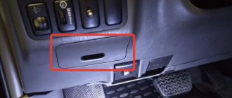
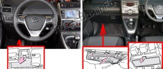
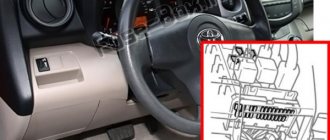
There are 2 options for location - right and left hand drive. Photo of fuses for Land Cruiser Prado 120 4 liters in the cabin:
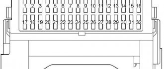
In the Toyota Prado 120, all fuses are installed on the instrument panel behind a plastic cover, and the relay is on the back of the mounting block.
Cigarette lighter and dimensions
On the Prado 120 4 liter, the cigarette lighter fuse is located in the same place where the TEMS and SRS (airbag system) are located - on the instrument panel in the cabin, has the serial number 24 and the abbreviation “CIG”.
The fuse for Prado 120 dimensions, regardless of which steering wheel (right or left), is marked “TAIL” No. 22 of the interior block. If it malfunctions, the turns do not turn on (do not light up), and the vehicle license plate illumination disappears. Relay No. 2 is also responsible for the sidelights.
TEMS system
The fuses of the TEMPS system in the Land Cruiser Prado 120 4 liters on the specified panel have serial number 6 and are marked “TEMS”. This electronically adjustable suspension was developed by Toyota for its line of cars. This system has several driving options (comfortable, sporty, ultra-comfortable, semi-sporty) and allows the car to respond adequately in the event of sharp turns, fast braking, and off-road driving. TEMS itself reconfigures the load on the Toyota Prado 120 axle, the stiffness of the shock absorbers, the height of the chassis, maintains vehicle stability and counteracts body roll to the side and in the transverse direction, as well as “nose dive” in case of braking.
Other
The following are responsible for lifting, cleaning and washing the front, side, rear windows and hatch:
- FR WIP−WSH (5);
- RR WIP (8);
- RR WSH (14);
- P FR P/W (18);
- P RR P/W, D RR P/W (19);
- P RR P/W, D RR P/W (20);
- POWER(20);
- power relay – R3.
Fuses for the socket in the cabin - PWR OUTLET (12), for the seats - DP/SEAT, PP/SEAT (10, 11), for the fuel pump - STA (17).
Fuse and relay diagram Toyota Land Cruiser Prado 120 / 125 (2002-2009)
Detailed explanation with photos, electrical diagram of fuse and relay blocks for Toyota cars.
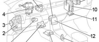
Salon
LHD
- Air conditioning control unit (automatic air conditioning (vehicles without navigation))
- Key transponder amplifier
- Fuse box
- Electronic adjustable suspension control unit
- Stability control control unit (VSC A/T)
- Body electrical control unit
- Anti-theft control unit
- Distribution block No. 1
- Distribution block No. 2
- Viscous heater amplifier
- Key transponder computer
- Distribution block No. 3
- Stability control control unit (VSC M/T)
- Air conditioning control unit (automatic air conditioning (vehicles with navigation)) Air conditioning control unit (manual air conditioning)
- Engine Control Module (M/T) Engine and Automatic Transmission Control Module (A/T)
- Center differential lock control unit Rear differential lock control unit
- Relay block
- Network Gateway Block
- Navigation control unit
- Refrigerator amplifier
- Gearbox selector lock control unit
- Audio amplifier
- Airbag unit
RHD
- Body electrical control unit
- Fuse box
- Stability control control unit (VSC)
- Network Gateway Block
- Airbag unit
- Navigation control unit
- Gearbox selector lock control unit
- Refrigerator amplifier
- Audio amplifier
- Relay block
- Center differential lock control unit Rear differential lock control unit
- Electronic adjustable suspension control unit
- Engine Control Module (M/T) Engine and Automatic Transmission Control Module (A/T)
- Air conditioning control unit (automatic air conditioning (vehicles with navigation)) Air conditioning control unit (manual air conditioning)
- Distribution block No. 3
- Key transponder computer
- Viscous heater amplifier
- Distribution block No. 2
- Air conditioning control unit (automatic air conditioning (vehicles without navigation))
- Distribution block No. 1
- Anti-theft control unit
- Double door lock relay
- Key transponder amplifier
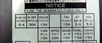
Fuse box in the passenger compartment
| № | Name | A | Purpose |
| 1 | IGN | 10 | Fuel pump control unit, multiport fuel injection system/sequential multiport fuel injection system, ABS, VSC, A-TRC |
| 2 | SRS | 10 | SRS airbag system |
| 3 | GAUGE | 7.5 | Instrument cluster |
| 4 | ST2 | 7.5 | Multiport fuel injection system/sequential multiport fuel injection system |
| 5 | FR WIP−WSH | 30 | Windshield wiper and washer |
| 6 | TEMS | 20 | Electronically adjustable suspension |
| 7 | DIFF | 20 | Rear differential lock, center differential lock |
| 8 | RR WIP | 15 | Rear wiper |
| 9 | — | — | — |
| 10 | DP/SEAT | 30 | LHD: Power driver's seat |
| PP/SEAT | 30 | RHD: Power Passenger Seat | |
| 11 | PP/SEAT | 30 | LHD: Power passenger seat |
| DP/SEAT | 30 | RHD: Power Driver Seat | |
| 12 | PWR OUTLET | 15 | Socket |
| 13 | IG1 NO.2 | 10 | Air conditioning, refrigerator |
| 14 | RR WSH | 15 | Rear window washer |
| 15 | ECU-IG | 10 | Gearbox selector lock, power windows, ABS, VSC, A-TRC, air conditioning, sunroof, sockets |
| 16 | IG1 | 10 | ABS, VSC, A-TRC, air conditioning, charging system, heated rear window, reversing lamps, turn indicators, hazard warning lights |
| 17 | S.T.A. | 7.5 | Fuel pump control unit |
| 18 | P FR P/W | 20 | Front passenger window lift |
| 19 | P RR P/W | 20 | LHD: Rear right power window |
| D RR P/W | 20 | RHD: Rear right power window | |
| 20 | D RR P/W | 20 | LHD: Rear left power window |
| P RR P/W | 20 | RHD: Rear left power window | |
| 21 | PANEL | 10 | Instrument panel lighting |
| 22 | TAIL | 10 | Side light, license plate light |
| 23 | ACC | 7.5 | Automatic transmission control unit, power outlets, power mirrors, audio system |
| 24 | C.I.G. | 10 | Cigarette lighter |
| 25 | POWER | 30 | Windows, sunroof |
| № | Relay |
| R1 | Sound signal |
| R2 | Side light |
| R3 | Power relay (window lifters, sunroof) |
| R4 | Sockets (ACC SKT) |
Relay box in the cabin
| № | Relay |
| R1 | Panel |
| R2 | Reversing lamps |
| R3 | Heated mirrors (MIR HTR) |
5 door cars
- Sunroof control unit
- Distribution block
- Rear A/C Relay
- Rear air conditioner amplifier
- Central locking receiver
3 door cars
- Sunroof control unit
- Distribution block
- Central locking receiver
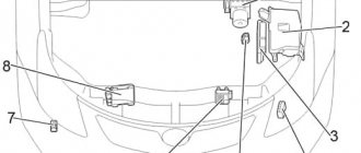
Engine compartment
- Relay block No. 1
- Fuse box
- Relay block No. 2
- Headlight wiper relay
- Stability control control unit (without VSC)
- Relay block #3 (LHD)
- Relay block #3 (RHD)
Fuse box in the engine compartment
| № | Name | A | Purpose |
| 1 | SPARE | 10 | Spare fuse |
| 2 | SPARE | 15 | Spare fuse |
| 3 | CDS FAN | 20 | Cooling fan |
| 4 | RR A/C | 30 | Rear air conditioner |
| 5 | WORLD HEATER | 10 | Heated mirrors |
| 6 | STOP | 10 | Brake Lamps, Auxiliary Brake Light, Shift Lock, ABS, VSC, A-TRC, Height Adjustable Rear Suspension |
| 7 | — | — | — |
| 8 | FR FOG | 15 | Front fog light |
| 9 | VISCUS | 7.5 | Viscous heater |
| 10 | OBD | 7.5 | Diagnostic connector |
| 11 | HEAD (LO RH) | 10 | Low right light |
| 12 | HEAD (LO LH) | 10 | Low left light |
| 13 | HEAD (HI RH) | 10 | Far right light |
| 14 | HEAD (HI LH) | 10 | Far left light |
| 15 | EFI NO.2 | 10 | Oxygen sensor, mass air flow sensor |
| 16 | HEATER NO.2 | 7.5 | Air conditioner |
| 17 | DEFOG | 30 | Heated rear window |
| 18 | AIRSUS NO.2 | 10 | Height-adjustable rear suspension |
| 19 | FUEL HEATER | 20 | Fuel heating |
| 20 | SEAT HEATER | 20 | Heated seats |
| 21 | DOME | 10 | Interior lighting, personal lighting, wireless remote control system, ignition switch lighting, door lighting |
| 22 | RADIO NO.1 | 20 | Audio system |
| 23 | ECU-B | 10 | ABS, VSC, A-TRC, air conditioning, refrigerator, power windows |
| 24 | ECU-B NO.2 | 10 | Body electrical control unit |
| 25 | — | — | Short pin |
| 26 | ALT−S | 7.5 | Charging system |
| 27 | — | — | — |
| 28 | HORN | 10 | Sound signal |
| 29 | A/F HEATER | 15 | Air fuel ratio sensor |
| F/PMP | 15 | 1KD−FTV: Fuel pump | |
| 30 | TRN−HAZ | 15 | Direction indicators, hazard warning lights |
| 31 | ETCS | 10 | Multiport fuel injection system/sequential multiport fuel injection system |
| 32 | EFl | 20 | Fuel pump control unit, fuel pump, multiport fuel injection system/sequential multiport fuel injection system |
| 25 | 1KD−FTV: Fuel pump control unit, fuel pump, multiport fuel injection system/sequential multiport fuel injection system | ||
| 33 | D FR P/W | 20 | Driver's window regulator |
| 34 | DR/LCK | 25 | central locking |
| 35 | — | — | — |
| 36 | RADIO NO.2 | 30 | Audio system |
| 37 | ALT | 120 | without PTC: Rear window defroster relay, ignition relay, fuses: “HEATER”, “CDS FAN”, “AM1”, “J/B”, “VISCUS”, “OBD”, “MIR HEATER”, “STOP”, “ FR FOG”, “AIRSUS”, “RR A/C” and “STOP” |
| 140 | with PTC: Rear window defroster relay, ignition relay, fuses: “HEATER”, “CDS FAN”, “AM1”, “J/B”, “VISCUS”, “OBD”, “MIR HEATER”, “STOP”, “ FR FOG”, “PTC-1”, “PTC-2”, “PTC-3”, “AIRSUS”, “RR A/C” and “STOP” | ||
| 38 | HEATER | 50 | Air conditioner |
| 39 | AIRSUS | 50 | Height-adjustable rear suspension |
| 40 | AM1 | 50 | Fuses: “ACC”, “CIG”, “IG1”, “IG1 NO.2”, “ECU-IG”, “FR WIP-WSH”, “RR WIP”, “RR WSH”, “DIFF”, “TEMS” ” and “STA” |
| 41 | PTC-1 | 40 | Auxiliary heater (PTC) |
| 42 | J/B | 50 | Fuses: “PWR OUTLET”, “P FR P/W”, “P RR P/W”, “D RR P/W”, “DP/SEAT”, “PP/SEAT”, “POWER”, “TAIL” and "PANEL" |
| 43 | PTC-2 | 40 | Auxiliary heater (PTC) |
| 44 | PTC-3 | 40 | Auxiliary heater (PTC) |
| 45 | ABS MTR | 40 | ABS, VSC, A-TRC |
| 46 | AM2 | 30 | Starting system, fuses: “IGN”, “GAUGE” and “SRS” |
| 47 | ABS SOL | 30 | without stability control: ABS |
| 50 | ABS (anti-lock braking system), VSC (stable stability control), A-TRC (active traction control) | ||
| 48 | GLOW | 80 | Glow plugs |
| Relay | |||
| R1 | Cooling fan (CDS FAN) | ||
| R2 | Auxiliary relay (ACC CUT) | ||
| R3 | Fog light | ||
| R4 | Starter (STA) | ||
| R5 | Ignition (IG) | ||
| R6 | Heater | ||
| R7 | Air Conditioning Compressor Clutch (MG CLT) | ||
| R8 | — | ||
| R9 | Heated rear window (DEFOG) | ||
| R10 | Anti-lock brake pump (ABS MTR) | ||
| R11 | Active Traction Control (TRC MTR) | ||
| R12 | Anti-lock brake system (ABS SOL) | ||
| R13 | Downhill Assist Control (DAC) | ||
| R14 | Fuel pump (C/OPN) or EDU | ||
| R15 | — | ||
| R16 | Engine control unit (EFI) | ||
| R17 | Air fuel ratio sensor (A/F HEATER) | ||
| R18 | Fuel pump | ||
| R19 | Headlights (HEAD) | ||
Relay block (No. 1)
| № | Relay |
| R1 | Starter (STA) |
| R2 | Glow plugs (GLOW) |
Relay block (No. 2)
| № | Relay |
| R1 | Air suspension (AIR SUS) |
| R2 | Dimmer (if equipped with daytime running lights) |
Relay block (No. 3)
| № | Relay |
| R1 | Auxiliary heater (PTC #1) |
| R2 | Auxiliary heater (PTC #2) |
| R3 | Auxiliary heater (PTC #3) |
On the website avto-fresh.com you can find a diagram of fuses and relays for Toyota Land Cruiser Prado 120 / 125 (2002-2009) photos and descriptions of the blocks, as well as answers to questions about where it is located and what it is responsible for. The designation of electrical equipment is described in detail in the article.
Under the hood
There are over 40 fuses and 19 relays under the hood. In addition, 7 more relays are combined into 3 independent blocks.
Problems in the main mounting block often occur when the battery is not charged correctly.
Air suspension and air conditioning
Air suspension fuses in a Prado 120 4 liter car - AIRSUS (39), AIRSUS NO.2 (18). The air suspension relay - AIR SUS is located in block No. 2.
Cars equipped with air suspension are more stable on the road and have less roll compared to cars with springs, including when driving off-road.
Other popular Prado 120 fuses:
- air conditioning – rear 4 (RR A/C), 16 (HEATER NO.2);
- radios - 22, 36 (RADIO NO.1, RADIO NO.2);
- fuel pump (fuel pump) - 29, 32 (A/F HEATER, F/PMP, Efl).
The starter relay (STA) in the Prado 120 4 liter car is in the main mounting block (R4) and in the relay block No. 1 (R1).
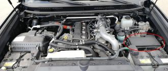
Fuse box in the engine compartment
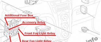
Fuse box location
Fuse box diagram
Purpose of fuses and relays in the engine compartment
| № | Name | ampere | scheme |
| 1 | SPARE | 10 | Spare fuse |
| 2 | SPARE | 15 | Spare fuse |
| 3 | CDS FAN | 20 | Electric cooling fan |
| 4 | RR A/C | 30 | Rear cooling system |
| 5 | HEATER | 10 | Heated exterior mirrors |
| 6 | STOP | 10 | Brake lights, overhead mounted brake light, Shift Lock Control, Anti-lock Braking System, Active Traction Control, Vehicle Stability Control, Rear Height Adjustable Air Suspension |
| 7 | – | – | – |
| 8 | FR FOG | 15 | Front fog lights |
| 9 | internal organ | 7,5 | Viscous heater |
| 10 | OBD | 7,5 | On-board diagnostic system |
| 11 | HEAD (LOW RIGHT) | 10 | Right headlight (low beam) |
| 12 | HEAD (LO LH) | 10 | Left headlight (low beam) |
| 13 | HEAD (HI RH) | 10 | Right headlight (high beam) |
| 14 | HEAD (HI LH) | 10 | Left headlight (high beam) |
| 15 | EFI No. 2 | 10 | 2 O2 sensors and air flow meter |
| 16 | HEATER No. 2 | 7,5 | Air conditioner |
| 17 | DEFOG | 30 | Heated rear window |
| 18 | AIRSUS No. 2 | 10 | Air suspension with rear height adjustment |
| 19 | FUEL HEATER | 20 | Fuel heater |
| 20 | HEATED SEAT | 20 | Heated seat |
| 21 | DOME | 10 | Interior lighting, personal lighting, wireless remote control system, ignition switch lighting, door lighting |
| 22 | RADIO No. 1 | 20 | Audio system |
| 23 | BUD-B | 10 | Anti-lock brakes, active traction control, vehicle stability control, air conditioning, refrigerator, power windows |
| 24 | ECU-B No. 2 | 10 | Multiplex communication system |
| 25 | – | – | Short pin |
| 26 | ALT-S | 7,5 | Charging system |
| 27 | – | – | – |
| 28 | HORN | 10 | Horns |
| 29 | HEATER A/F | 15 | A/F sensor |
| 29 | F/PMP | 15 | 1KD-FTV: Fuel pump |
| 30 | TRN-ZTVA | 15 | Turn signals, hazard flashers |
| 31 | ETCS | 10 | Multiport fuel injection system/sequential multiport fuel injection system |
| 32 | EFI | 20 | Electronically Controlled Fuel Pump, Fuel Pump, Multiport Fuel Injection System/Sequential Multiport Fuel Injection System |
| 32 | EFI | 25 | 1KD-FTV: Electronically controlled fuel pump, fuel pump, multiport fuel injection system/sequential multiport fuel injection system |
| 33 | DFR P/W | 20 | Driver's power window |
| 34 | DR/LCK | 25 | Power door lock system |
| 35 | – | – | – |
| 36 | RADIO No. 2 | 30 | Audio system |
| 37 | ALT | 120 | without PTC: fog relay, ignition relay, "HEATER", "CDS FAN", "AM1", "J/B", "VISCUS", "OBD", "MIR HEATER", "STOP", "FR FOG", Fuses “AIRSUS”, “RR A/C” and “STOP” |
| 37 | ALT | 140 | with PTC: defogging relay, ignition relay, "HEATER", "CDS FAN", "AM1", "J/B", "VISCUS", "OBD", "MIR HEATER", "STOP", "FR FOG", Fuses "PTC-1", "PTC-2", "PTC-3", "AIRSUS", "RR A/C" and "STOP" |
| 38 | HEATER | 50 | Air conditioner |
| 39 | AIRSUS | 50 | Air suspension with rear height adjustment |
| 40 | AM1 | 50 | All components in "ACC", "CIG", "IG1", "IG1 NO.2", "ECU-IG", "FR WIP-WSH", "RR WIP", "RR WSH", "DIFF", " Fuses "TEMS" and "STA" |
| 41 | PTC-1 | 40 | Viscous heater |
| 42 | J/B | 50 | All components in "PWR OUTLET", "P FR P/W", "P RR P/W", "D RR P/W", "DP/SEAT", "PP/SEAT", "POWER", "TAIL" "fuses" and "panel" |
| 43 | PTC-2 | 40 | Viscous heater |
| 44 | PTC-3 | 40 | Viscous heater |
| 45 | ABS MTR | 40 | Anti-lock braking system, active traction control, vehicle stability control |
| 46 | AM2 | 30 | Starter system, fuses "IGN", "GAUGE" and "SRS" |
| 47 | ABS SOL | 30 | without vehicle stability control: anti-lock braking system |
| 47 | ABS SOL | 50 | with Vehicle Stability Control: Anti-lock Braking System, Active Traction Control, Vehicle Stability Control |
| 48 | GLOW | 80 | Engine glow system |
| Relay | |||
| R1 | Electric cooling fan (CDS FAN) | ||
| R2 | Accessory (ACC CUT) | ||
| R3 | Fog lights | ||
| R4 | Starter (STA) | ||
| R5 | Ignition (IG) | ||
| R6 | heater | ||
| R7 | Air Conditioning Compressor Clutch (MG CLT) | ||
| R8 | – | ||
| R9 | Heated rear window (DEFOG) | ||
| R10 | Anti-lock braking system (ABS MTR) | ||
| R11 | TRC MTR | ||
| R12 | Anti-lock braking system (ABS SOL) | ||
| R13 | Descent Assist Control (DAC) | ||
| R14 | Circuit Opening Relay (C/OPN) or EDU | ||
| R15 | – | ||
| R16 | EFI | ||
| R17 | Air fuel ratio sensor (A/F HEATER) | ||
| R18 | Fuel pump | ||
| R19 | Headlight (HEAD) |
Relay block No. 1
| № | Relay |
| R1 | Starter (STA) |
| R2 | Glow system (GLOW) |
Relay block No. 2
| № | Relay |
| R1 | Air suspension (AIR SUS) |
| R2 | Dimmer (with daytime running lights) |
Changing fuses correctly
Not every Prado 120 driver knows what to do if the fuse fails. Before you familiarize yourself with the sequence of actions for replacing a part, you need to understand whether it really needs to be replaced:
- They are looking for a block of fuse links to which non-functioning units lead.
- Find the fuse connected to the electrical appliance. The diagram will speed up the search.
- Use special tongs to remove the fusible insert.
- Inspect it for visual damage and defects. If the owner finds deficiencies, then it needs to be replaced.
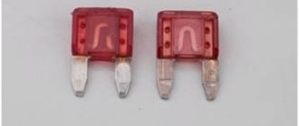
Checking the fuse: 1. Good fuse. 2. Blown fuse.
The damaged fuse is replaced with a serviceable one, which is purchased at the store. Plastic must have a flat surface, and on metal there should be no change in cross-section. If you have any concerns, test it before installing.
Fuse set
Instructions:
- Buy a second Prado 120 fuse link as a spare for the main one.
- Attach to the metal bases of the cable fuse.
- Connect one end to the plus, the other to the minus.
See how the fuses behave. A high-quality one will burn out, a low-quality one will melt.
Replacement consists of installing a new fuse-link instead of the damaged one. Check out some details:
- If necessary, identify and eliminate the cause of the short circuit so that the new product does not deteriorate again.
- There are three types of machine fuses: mini, medium and maximum. Each size fits into its proper place.
- The current strength in the fuse link should not exceed the nominal value, otherwise the Prado devices will burn out.
- The unit should not contain bare wires that are connected to the housing to prevent a short circuit.
- After installation, the parts are checked for correct functioning of all electrical components.
