The main purpose of a fuse box is to control loads and prevent short circuits in electrical connections. The elements of the block break the circuit when the electric current (voltage) indicators remain at a critical level for a long time.
Most of the power supply circuits for the electrical equipment of the machine are protected by fuses. Devices that consume large amounts of electricity (for example, a gas pump and electric power steering) are connected via a relay. Failure of these parts can lead to failure of the entire vehicle system, as well as accidental fire.
Toyota RAV4 Fuse Boxes
Sudden surges in current usually occur due to a fault in the circuit (short circuit). Therefore, almost all electrical wiring connecting vehicle equipment has protection elements. The most energy-intensive areas are connected via a relay.
For ease of use, all these current controllers are combined into special mounting blocks, which are located in the passenger compartment and under the hood of the car.
Below are typical diagrams of electrical fuses in blocks for 4th generation cars (from 2012 to the present).
It is important to remember that these schemes will only be useful to owners of cars of the latest generation, because... fuses for Toyota RAV4 2008, 2009 or 2010 will be located in a different order.
RAV4 fuse diagram in the cabin
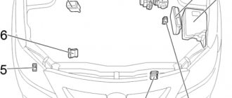
RAV4 fuse diagram in the engine compartment
If the diagrams presented above do not match the location in the car, then the decoding of the values described below will not be relevant.
Blocks under the hood
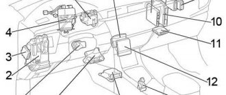
General arrangement of blocks
Scheme
Description
- Fuse and relay box
- Headlight wiper relay
- ABS control unit
- LHD:
Power fuse block - RHD:
Power fuse block
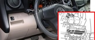
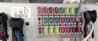
Fuse box in the passenger compartment
The left corner of the interior dashboard contains a mounting block in which fuses are located for the main electrical circuits and components of the car inside the body.
Here is their purpose:
| Current indicator | Name of the circuit protected by the controllers | Connector number on the diagram |
| – | – (empty) | 1 |
| 7.5A | Brake lamps and indicators | 2 |
| 10A | Hatch opening mechanism | 3 |
| 5A | Elements marked “IG1 No. 1”, “IG1 No. 2”, “IG1 No. 3”, “ACC” | 4 |
| 7.5A | Diagnostic connector | 5 |
| 20A | Central locking device, control over body electrical systems (before restyling 2015) | 6 |
| 7.5A | Rear fog light | 7 |
| 10A | Central locking module (tailgate) | 8 |
| 15A | Cigarette lighter socket | 9 |
| 20A | Window lift mechanism, driver's door | 10 |
| 20A | Window lifter rear right | 11 |
| 20A | Window lifter, rear left | 12 |
| 15A | Rear glass cleaner | 13 |
| 15A | Window washers | 14 |
| 7.5A | Rear warning lights, parking sensors, blind spot controller, auto-dimming interior mirrors | 15 |
| 25A | Glass cleaning | 16 |
| 5A | Gearbox blocker | 17 |
| 15A | Socket | 18 |
| 7.5A | System of electric mirrors, sockets, control unit for body electrical equipment, audio system, clock | 19 |
| 7.5A | All-wheel drive control, heated brush area, fuel injection, parking sensors, heated seats, trunk (lid), air conditioning, heated rear glass, audio system, control of steering wheel buttons, illuminated cup holders | 20 |
| 10A | Dimensions, fog lights, state lights. numbers | 21 |
| 20A | Center. lock, body electrical equipment (from the restyled version 2015) | 22 |
| 5A | Power steering | 23 |
| 10A | Control of all-wheel drive, steering wheel, gear selector | 24 |
| 5A | Control of equipment in the middle of the cabin, wireless. management, arts. intelligence, gearbox lock, trunk, tire pressure monitoring, audio system, blind spot and lane monitoring | 25 |
| 7.5A | Air conditioning and heated rear glass | 26 |
| 10A | Seat heating (left) | 27 |
| 10A | Seat heating (right) | 28 |
| 7.5A | Fuel pump, fuel injection, indicator lights and steering lock | 29 |
| 7.5A | Airbags | 30 |
| 5A | Combinations of mechanisms | 31 |
| 7.5A | Generator control, ABS/VSC, brush heating device in the rest zone, light indicators, elements marked “FAN No. 1”, “FAN No. 2”, “FAN No. 3”, “HTR”, “PTC”, “DEF”, "DEICER" | 32 |
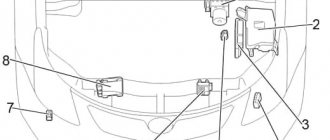
Motor block
To begin with, it is worth considering compartment A. The layout of the fuses in this compartment is presented below in the form of an image.
To understand which fuse is responsible for what, it is worth looking at the table, which shows the main elements.
| Designation | Purpose |
| 1 | Provides fuel supply to the fuel pump. |
| 3 | Adjusts the steering wheel lock. |
| 4 | Supplies electricity to air conditioning and heater. |
| 5 | Ensures the functionality of instruments and indicators. |
| 11 | Starts the engine. |
| 24 | Responsible for the operation of the windshield washer. |
| 27,28 | Turns on/off the left and right headlights. |
Engine compartment
The right side of the engine compartment (as the car moves) contains a mounting block where fusible jumpers are located to the rest of the electrical circuits and components of the car
.
Their purpose is as follows:
| Current indicator | Name of the circuit protected by the controllers | Connector number on the diagram |
| 20A | Audio system | 1 |
| 10A | Body electronics, wireless. controls, steering wheel, tire pressure, clock, luggage compartment (lid) | 2 |
| 10A | Light in the cabin, trunk, mirror illumination | 3 |
| – | – | 4 |
| 20A | Heating brushes at rest | 5 |
| – | – | 6 |
| 7.5A | Fog | 7 |
| 30A | Audio system | 8 |
| 30A | Starter | 9 |
| 20A | Elements marked “EFI No. 1”, “EFI No. 2”, fuel injection | 10 |
| – | – | 11 |
| 15A | Items marked "METER", "IGN", "A/B", fuel injection | 12 |
| 10A | Node Combinations | 13 |
| 7.5A | Starter, fuse marked “IG2” | 14 |
| 10A | Air conditioning, front seat passenger detection system, smart entry and start system | 15 |
| 10A | Steering wheel lock | 16 |
| 30A | Elements marked “DOME”, “ECU-B No. 1”, “RADIO” | 17 |
| 10A | Klaxon | 18 |
| 10A | Pulse injection device | 19 |
| 20A | Air consumption, fuel pump, rear oxygen controller | 20 |
| 7.5A | Electric current indicator | 21 |
| 10A | Heated mirrors, fuel injection | 22 |
| 10A | Air distribution controller, VSV, ACIS VSV | 23 |
| 10A | Fuel injection | 24 |
| 10A | Far left lighting, far detector | 25 |
| 10A | Far right lighting | 26 |
| – | – | 27 |
| 10A | Low left headlight | 28 |
| 10A | Low beam right | 29 |
| 30A | Engine cooling unit | 30 |
| 50A | Air conditioning control | 31 |
| 50A | Daylighting, elements marked “H-LP RH-LO”, “H-LP LH-LO”, “H-LP RH-HI”, “H-LP LH-HI” | 32 |
| 30A | Additional heating | 33 |
| 30A | Additional heating | 34 |
| 30A | Rear defogger, elements marked “MIR HTR” | 35 |
| 30A | V.S.C. | 36 |
| 30A | Cooling | 37 |
| 50A | V.S.C. | 38 |
| 80A | EUR | 39 |
| 120A | Elements marked “ABS No. 1”, “ABS No. 2”, “PTC HTR No. 1”, “PTC HTR No. 2”, “DEICER”, “HTR”, “RDI FAN”, “CDS FAN”, “FOG FR” ", "DEF" | 40 |
| 5A | Window cleaners and rain controller | 41 |
| 10A | Spare controllers | 42 |
| 20A | 43 | |
| 30A | 44 | |
| Relay | ||
| Engine control system (EFI-MAIN No. 2) | R1 | |
| Ignition (IG2) | R2 | |
| Fuel pump (C/OPN) | R3 | |
| Switches | R4 | |
| Lighting technology (H-LP) | R5 | |
| Motor control (EFI-MAIN No. 1) | R6 | |
| Heated glass rear (DEF) | R7 | |
| Daylight control | M1 | |
Fuse and relay diagram Toyota RAV4 (2000-2005; XA20)
Detailed explanation with photos, electrical diagram of fuse and relay blocks for Toyota cars.
| Toyota RAV4 | |||
| 1994-2000 | 2002-2005 | 2006-2012 | 2013-2018 |
Salon
LHD
RHD
- Fuse box
- LHD:
Side light relay - Key transponder amplifier
- Air conditioner amplifier
- Engine and transmission control unit (A/T) Engine control unit (M/T)
- Distribution block
- Distribution block
- Airbag central unit
- Gearbox selector lock control unit
- Turn signal relay (hazard warning lights)
Fuse box in the passenger compartment
| № | Name | A | Purpose |
| 1 | STOP | 10 | Brake Lamps, Auxiliary Brake Light, ABS, Shift Lock, Cruise Control, Multiport Fuel Injection System/Sequential Multiport Fuel Injection System |
| 2 | C.I.G. | 15 | Cigarette lighter |
| 3 | POWER OUTLET | 15 | Socket |
| 4 | S-HTR | 10 | Heated seats |
| 5 | PANEL | 7.5 | Instrument panel lights, instrument cluster, front fog light, heated mirrors, air conditioning |
| 6 | FR FOG | 15 | Front fog light |
| 7 | HORN | 10 | Sound signal |
| 8 | TAIL | 7.5 | Side light, license plate light, instrument panel light |
| 9 | TAIL&PANEL | 15 | Fuses “PANEL”, “TAIL” |
| 10 | ACC | 7.5 | Audio system, gearshift lock, clock, power mirrors |
| 11 | DEF | 20 | Heated rear window |
| 12 | GAUGE | 10 | Reversing lamps, cooling fan, air conditioning, automatic transmission indicators, charging system |
| 13 | OBD | 7.5 | Diagnostic connector |
| 14 | IG2 | 10 | Low Battery Indicator, Multiport Fuel Injection System/Sequential Multiport Fuel Injection System, Starting System, Airbags, Instrument Cluster |
| 15 | DOOR | 20 | central locking |
| 16 | MIR HTR | 10 | Heated mirrors |
| 17 | RR WIP | 15 | Rear wiper and washer |
| 18 | WIP | 25 | Windshield wiper and washer |
| 19 | ECU IG | 10 | Hazard warning lights, instrument cluster, ABS, airbags, gearshift lock, cruise control, VSC, TRC |
| 20 | POWER | 30 | Sunroof, power windows |
| 21 | AM1 | 40 | Sockets, heated rear window, fuses: “ACC”, “CIG”, “ECU IG”, “GAUGE”, “RR WIP”, “S−HTR” and “WIP” |
| № | Relay |
| R1 | Sound signal |
| R2 | Rear Fog Light (RR FOG) |
| R3 | Heated rear window (DEF) |
| R4 | Outlets (PWR OUTLET) |
| R5 | Power windows, sunroof (PWR) |
5 door models
3 door models
- Relay and sunroof control unit
- Rear wiper relay
- Central locking receiver
Engine compartment
- Fuse box
- Headlight wiper relay
- ABS control unit
- LHD:
Power fuse block - RHD:
Power fuse block
Fuse box in the engine compartment
| № | Name | A | Purpose |
| 1 | — | — | Jumper |
| 2 | ALT-S | 5 | Charging system |
| 3 | A/F | 20 | Air fuel ratio sensor |
| RADIO NO.2 | 30 | Audio system | |
| 4 | EFI1 | 20 | Multiport fuel injection system/sequential multiport fuel injection system, automatic transmission oil temperature sensor, fuses: “EFI2”, “EFI3” |
| 5 | CUT | 30 | Fuses: “RADIO”, “DOME” |
| 6 | HAZ | 10 | Alarm |
| 7 | EFI2 | 5 | Multiport fuel injection system/sequential multiport fuel injection system |
| 8 | ABS 2 | 30 | ABS, VSC, TRC, Brake Assist |
| 9 | DOME | 10 | Personal lighting, clock, interior lighting, air conditioning, wireless remote control system, high beam indicator, instrument cluster |
| 10 | MAIN | 30 | Fuses: “H−LP RH” and “H−LP LH” |
| 11 | EFI3 | 10 | Multiport fuel injection system/sequential multiport fuel injection system, emission control system |
| 12 | RADIO | 15 | Audio system |
| 13 | A/C | 5 | Air conditioner |
| 14 | IGN | 15 | Starting system, multiport fuel injection system/sequential multiport fuel injection system |
| 15 | — | — | — |
| 16 | — | — | — |
| 17 | ETCS | 10 | Electronic throttle control system |
| 18 | H−LP RH | 10 | Right headlight |
| 19 | H−LP LH | 10 | Left headlight |
| 20 | INJ | — | Multiport fuel injection system/sequential multiport fuel injection system |
| 21 | ST | 5 | Starting system |
| 22 | AM2 | 30 | Low Battery Indicator, Multiport Fuel Injection System/Sequential Multiport Fuel Injection System, Starting System, Airbags, Fuse: “IG2” |
| 23 | HTR | 40 | Air conditioner/heater |
| 24 | H−LP CLN | 30 | Headlight cleaners |
| F−HTR | 30 | Fuel heating | |
| 25 | CDS | 30 | Cooling fan |
| 26 | ABS 1 | 40 | ABS |
| 50 | ABS | ||
| 27 | RDI | 30 | Cooling fan |
| Relay | |||
| R1 | Engine control unit (EFI MAIN) | ||
| R2 | Cooling fan (FAN NO.3) | ||
| R3 | Ignition (IG2) | ||
| R4 | Cooling fan (FAN NO.2) | ||
| R5 | Air fuel ratio (A/F) sensor | ||
| R6 | Cooling fan (FAN NO.2) | ||
| R7 | Fuel pump (C/OPN) | ||
| R8 | Heater (HTR) | ||
| R9 | Starter (ST) | ||
| R10 | Daytime running lights (DRL) | ||
| R11 | The engine control unit | ||
| R12 | — | ||
On the website avto-fresh.com you can find a diagram of fuses and relays for Toyota rav4 (2000-2005; xa20), photos and descriptions of the blocks, as well as answers to questions about where it is located and what it is responsible for. The designation of electrical equipment is described in detail in the article.
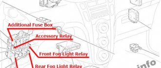
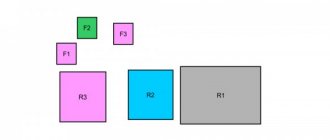
Additional block
The additional block contains only four fuses. Each of them is presented in the diagrams separately for cases where the steering wheel is located on the right or on the left. Also below is a breakdown of what each element is responsible for.
- This element is responsible for the electric drive of the left seat.
- The same thing, but for the right seat.
- In this case, the element is used to organize the operation of the tailgate.
- Fuse for front power windows.
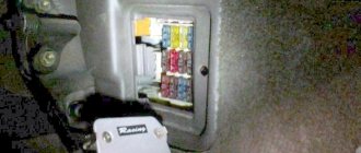
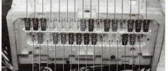
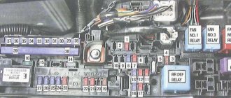
Mounting block
This unit can be found under the dashboard of a Toyota RAV4.
The arrangement of fuses in the block is as follows:
As for the designation and purpose, the decoding of the numbering looks like this:
| Designation | Purpose |
| 1 | Stop light operation. |
| 2 | Opening/closing the hatch. |
| 5 | Door lock. |
| 6 | Operation of fog lights. |
| 15 | Windshield wiper operation. |
| 14 | Turn on/off the reversing lights. |
| 20 | Turning on/off side lights. |
| 25,26 | Heated seats. |
The table shows only the most popular fuses. The block also contains elements that are responsible, for example, for the operation of various sensors in the system and the cigarette lighter. They also provide electricity to the car's outlets, control the audio system, heater, and other functions or devices of the vehicle. This also includes fuses that regulate the operation of airbags, the fuel pump and the generator.
Passenger cabin
location
System
LHD
Right hand drive
Task
- Fuse box
- LHD: Side light relay
- Key transponder amplifier
- Air conditioner amplifier
- Engine and transmission control unit (A/T) Engine control unit (M/T)
- Distribution block
- Distribution block
- Central airbag
- Shift Lever Lock Control Unit
- Turn signal relay (alarm)
Diagram of additional elements
Description
- Sunroof relay and control unit
- Rear wiper relay
- Central locking receiver