Fuse box in the passenger compartment
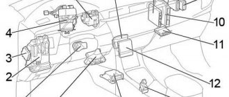
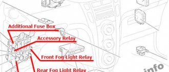
Fuse box location
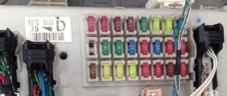
The fuse box is located under the instrument panel (on the left side), behind the cover.
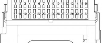
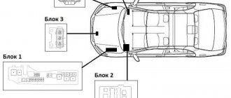
Fuse box diagram
Purpose of fuses in the car interior
| № | Name | ampere | scheme |
| 1 | – | – | Not used |
| 2 | S-HTR | 15 | Seat heating |
| 3 | WIP | 25 | Wipers |
| 4 | RR WIP | 15 | Rear window wiper |
| 5 | WSH | 15 | Windshield washer, rear window washer |
| 6 | ECU-IG1 | 10 | Electric Cooling Fans, Anti-Lock Braking System, Traction Control System, Vehicle Stability Control System, Hill Descent Control, Hill Start Control, Active Torque Control 4WD, Automatic Transmission Shift Lock System, Air Conditioning System, Main Body ECU. power sunroof, windshield wiper defroster, brake/tail lights, power steering, clock, auto anti-glare rearview mirror |
| 7 | ECU-IG2 | 10 | Air conditioning system, heated rear window |
| 8 | OBD | 7,5 | On-board diagnostic system |
| 9 | STOP | 10 | Brake/Tail Lights, High Mounted Brake Light, Automatic Transmission Shift Lock System, Multiport Fuel Injection System/Sequential Multiport Fuel Injection System, Anti-Lock Brake System, Traction Control System, Vehicle Stability Control System, Hill Descent Control hill, hill start assistance control system |
| 10 | – | – | Not used |
| 11 | DOOR | 25 | Main body ECU, power door lock system |
| 12 | ASS-B | 25 | Fuses “ACC”, “CIG” |
| 13 | 4WD | 7,5 | Active Torque Control 4WD |
| 14 | FR FOG | 15 | Front fog lights |
| 15 | AM1 | 7,5 | Starting system |
| 16 | TAIL | 10 | Tail lights, parking lights, license plate lights, front fog lights, rear fog lights |
| 17 | PANEL | 7,5 | Clock, instrument panel lights, audio system |
| 18 | GAUGE1 | 10 | Connectable lights, charging system |
| 19 | D FRONT DOOR | 20 | Power windows (front doors) |
| 20 | RL DOOR | 20 | Power windows |
| 21 | BACKDOOR | 20 | Power windows |
| 22 | S/ROOF | 25 | Electric moon roof |
| 23 | C.I.G. | 15 | Lighter |
| 24 | ACC | 7,5 | Audio system, electrical outlets, power rearview mirror control, automatic transmission shift lock system, main body ECU, clock |
| 25 | – | – | Not used |
| 26 | WORLD OF HTR | 10 | External rear heaters |
| 27 | SOCKET PWR | 15 | Sockets |
| 28 | – | – | Not used |
| 29 | RR FOG | 10 | Rear fog light |
| 30 | IGN | 7,5 | SRS Airbag System, Multiport Fuel Injection System/Sequential Multiport Fuel Injection System, Brake Lights/Tail Lights, Starting System |
| 31 | GAUGE2 | 7,5 | Meters and gauges |
| № | Name | ampere | scheme |
| 1 | POWER | 30 | Power windows |
| 2 | DEF | 30 | Heated rear window, fuse “MIR HTR” |
| 3 | P/SEAT | 30 | Power seat |
| Relay | |||
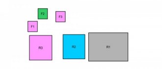
| R1 | Ignition (IG1) | ||
| R2 | Heater (manual air conditioner), short pin (automatic air conditioner) | ||
| R3 | LHD: turn signal |
Relay block
| № | Relay |
| R1 | Starter (ST CUT) |
| R2 | LHD: Starter (ST) (petrol, before December 2008: diesel with entry and start system) LHD: short pin (before December 2008: diesel without entry and start system) |
| R3 | Front fog lamp (FR FOG) |
| R4 | Rear Fog Light (RR FOG) Socket (115V) |
| R5 | Accessory (ACC) |
| R6 | Power outlet (PWR OUTLET) |
Changing fuses correctly
Every Rav 4 car owner can experience a blown fuse link. Let's look at how to properly replace the fuse.
First you will need to identify the damaged element. To do this, the list of electrical equipment that has failed is analyzed, after which the failed element is determined from the lists presented above. It is removed from the seat with special forceps or by hand. The negative terminal from the battery is first removed.
In the future, the cause of the insert burnout must be identified and eliminated. All that remains is to insert a new protective element identical in current rating.
Whole fuse
Fuse blocks in the engine compartment
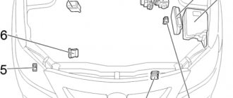
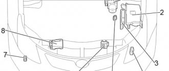
Fuse box location
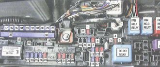
Fuse block diagram No. 1
Assignment of fuses and relays in fuse box No. 1 in the engine compartment.
| № | Name | ampere | scheme |
| 1 | – | – | Not used |
| 2 | – | – | Not used |
| 3 | – | – | Not used |
| 4 | BUD-V2 | 7,5 | Air conditioning system, electric windows |
| 5 | ALT-S | 7,5 | Charging system |
| 5 | RGP | 7,5 | Audio system (JBL) |
| 6 | STR LOCK | 20 | No chain |
| 7 | – | – | Not used |
| 8 | DCC | – | – |
| 9 | RAD No. 1 | 20 | Audio system |
| 10 | BUD-B | 10 | Wireless Remote Control System, Main Body ECU, Clock, Meters, Sensors and Vehicle Stability Control System, Electric Power Steering System |
| 11 | DOME | 10 | Ignition switch lighting, interior lighting, vanity lighting, trunk lighting, front personal lights, footwell lights |
| 12 | – | – | – |
| 13 | HEAD LEFT | 10 | Left headlight (high beam) |
| 14 | HEAD IS RIGHT. | 10 | Right headlight (high beam) |
| 15 | HEAD LL | 10 | Left headlight (low beam) |
| 16 | HEAD RL | 10 | Right headlight (low beam) |
| 17 | – | – | – |
| 18 | AC INV | 15 | Outlet (115V) |
| 19 | TOWING | 30 | Towing a trailer |
| 20 | STV HTR | 25 | No chain |
| 21 | – | – | Not used |
| 22 | defroster | 20 | Deicer front window |
| 23 | HTR | 50 | Air conditioner |
| 24 | PTC3 | 50 | PTC heater |
| 25 | PTC2 | 50 | PTC heater |
| 26 | PTC1 | 50 | PTC heater |
| 27 | HOME HOME | 50 | Fuses “HEAD LL”, “HEAD RL”, “HEAD LH”, “HEAD RH” |
| 28 | – | – | Not used |
| 29 | RDI | 30 | without towbar (except 2GR-FE): Electric cooling fans |
| 29 | FAN2 | 50 | with towbar (2GR-FE): Electric cooling fans |
| 30 | CDS | 30 | without towbar (except 2GR-FE): Electric cooling fans |
| 30 | FAN1 | 50 | with towbar (2GR-FE): Electric cooling fans |
| 31 | H-LP CLN | 30 | No chain |
| Relay | |||
| R1 | Dimmer | ||
| R2 | headlight | ||
| R3 | Daytime running lights relay (No. 4) | ||
| R4 | Daytime running lights relay (No. 3) | ||
| R5 | Except 2GR-FE: Electric cooling fan (No. 3) | ||
| R6 | Except 2GR-FE: Electric cooling fan (No. 2) | ||
| R7 | Except 2GR-FE: Electric cooling fan (No. 1) | ||
| R8 | Not used | ||
| R9 | Deicer front window | ||
| R10 | Daytime running lights relay (No. 2) | ||
| R11 | Except 2GR-FE: PTC heater (PTC No. 3) | ||
| R12 | Except 2GR-FE: Positive Temperature Coefficient Heater (PTC No. 2) 2GR-FE: Electric Cooling Fan (No. 2) | ||
| R13 | 2GR-FE: Electric cooling fan (No. 1) Except 2GR-FE: Positive temperature coefficient heater (PTC No. 1) |
Fuse block diagram No. 2
Assignment of fuses and relays in fuse box No. 2 in the engine compartment.
| № | Name | ampere | scheme |
| 1 | R-SYSTEM | 30 | 3ZR-FAE: Valve lift control drive |
| 2 | AMP | 30 | Audio system (JBL) |
| 3 | AM2 | 30 | Starting system |
| 4 | IG2 | 15 | Engine control, ignition |
| 5 | HAZ | 10 | Emergency flashers |
| 6 | ETCS | 10 | Cruise control, electronically controlled transmission and automatic transmission indicator, engine management, engine immobilizer |
| 7 | AM2-2 | 7,5 | Starting system |
| 8 | – | – | – |
| 9 | EFI #1 | 10 | Multiport fuel injection system/sequential multiport fuel injection system |
| 10 | EFI No. 2 | 10 | Multiport fuel injection system/sequential multiport fuel injection system |
| 11 | EFI No. 3 | 7,5 | IN; From December 2008: Multiport fuel injection system/sequential multiport fuel injection system. |
| 11 | S.T.A. | 7,5 | Starting system, multiport fuel injection system/sequential multiport fuel injection system |
| 12 | GLOW | 80 | Engine glow system |
| 13 | EM PS | 60 | Electric power steering |
| 14 | BASIC | 80 | Fuses "HEAD MAIN", "ECU-B2", "DOME", "ECU-B", "RAD NO.1" |
| 15 | ALT | 120 | Petrol, (without towing package): fuses "ABS 1", "ABS 2", "RDI", "CDS", "HTR", "TOWING" |
| 15 | ALT | 140 | Diesel, (with towing kit): fuses "ABS 1", "ABS 2", "RDI", "CDS", "HTR", "TOWING" |
| 16 | PI | 50 | Fuses “EFI MAIN”, “HORN”, “A/F”, “EDU” |
| 17 | – | – | Not used |
| 18 | ABS 2 | 30 | Anti-lock brake system, traction control, vehicle stability control, hill descent control, hill start control |
| 19 | ABS 1 | 50 | Anti-lock brake system, traction control, vehicle stability control, hill descent control, hill start control |
| 20 | EFI HOME | 20 | Multiport fuel injection system/sequential multiport fuel injection system, “EFI NO.1”, “EFI NO.2”, “EFI NO.3” fuses |
| 21 | HORN | 10 | horn |
| 22 | EDU | 25 | Multiport fuel injection system/sequential multiport fuel injection system |
| 23 | A/F | 20 | Gasoline: A/F sensor Diesel: Multiport fuel injection system/Sequential multiport fuel injection system |
| 23 | IGT/INJ | 15 | 3ZR-FAE: Multipoint fuel injection system/sequential multiport fuel injection system |
| Relay | |||
| R1 | Relay VSC MTR | ||
| R2 | Not used | ||
| R3 | VSC FAIL relay | ||
| R4 | Ignition (IG2) | ||
| R5 | Relay BRK | ||
| R6 | Air conditioning (MG CLT) | ||
| R7 | Fuel pump |
Selection of components
For the third generation RAV 4, you can purchase an original fuse box, marked with article number 8273042010 . You can buy it, for example, at a showroom. For installation on models manufactured since 2013, components with catalog number 8274142031 .
When purchasing analogues, you need to consider the following values:
- Rated tripping rate (must exceed the periodic component of the pending short-circuit current).
- Rated current of the device.
- Rated voltage of the fuse (cannot be less than the rated voltage of the car's electrical network).
- The time-current characteristics of the fuse must be lower than the load on it.
Rely on color coding. For example, to repair a cigarette lighter, you need a blue fuse with the number “15” indicating the current in amperes. The fuse responsible for the heated windshield is yellow, marked “20”. The element protecting the seat heating system is blue, marked “15”. Accordingly, the color directly depends on the current strength.
Shades may vary slightly, but color coding is generally followed by all manufacturers.
Never use a jumper wire instead of a fuse! This leads to critical damage to the vehicle's electrical circuit.
You can purchase high-quality fuses that will last for years at almost any auto parts store. You should not buy too cheap components from unknown manufacturers - no one guarantees that they will work correctly.
