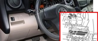
Fuse and relay box in the interior of Toyota Corolla 150 (Block A)
Located inside the cabin, to the left of the driver. You can find it under the side mirror control button, inside the small items drawer.
Removing it reveals a small box with 3 fuses and relay devices.
Toyota Corolla fuses are designated by the letter f and supplemented by a number:
- Electronic control unit.
- Power supply for turn signal switch.
- Backup protection.
Relays are designated by the letter R with an additional number:
- Turn signal breaker.
- Heater.
- Injector IG1.
Fuse box in the engine compartment
The fuses are located in the block, which is located under the hood, as shown in the figure:
The figure below shows the designation of fuses according to their positions.
The table shows the purpose of the fuses, their position number and rating.
| Position F | Purpose | Denomination |
| 1 | Headlight washer | 30 Amps |
| 2 | Electric cooling system drive | 45 Amps |
| 3 | ABS and VSC | 30 Amps |
| 4 | ABS and VSC | 50 Amps |
| 5 | Air conditioner fan | 50 Amps |
| 6 | Robotic gearbox | 10 Amps |
| 7 | Dashboard, ECU body control unit, central locking, power windows, VSC. | 10 Amps |
| 8 | Radio tape recorder | 15 Amps |
| 9 | Interior and trunk lighting | 10 Amps |
| 10 | Steering lock | 20 Amps |
| 11 | Starter, injection control | 30 Amps |
| 12 | Throttle control | 10 Amps |
| 13 | Turn signals, emergency lights | 10 Amps |
| 14 | Battery charge current control circuits | 7.5 Amps |
| 15 | Body control unit | 7.5 Amps |
| 16 | Head light | 50 Amps |
| 17 | ECU | 50 Amps |
| 18 | Glow plug preheating | 80 Amps |
| 19 | Electric power steering | 60 Amps |
| 20 | Battery charging circuits | 120 Amps |
| 21 | ECU | 15 Amps |
| 22 | Sound signal | 10 Amps |
| 23 | Electronic engine control unit | 20 Amps |
| 24 | Spare | |
| 25 | Spare | |
| 26 | Spare | |
| 27 | Automatic gearbox overeating (robot) | 50 Amps |
| 28 | Air conditioning system control | 30 Amps |
| 29 | Air conditioning system control | 30 Amps |
| 30 | Air conditioning system control | 30 Amps |
| 31 | Low right light | 10 Amps |
| 2 | Low left light | 10 Amps |
| 33 | Far right light | 10 Amps |
| 34 | Left high beam | 10 Amps |
| 35 | Electronic engine control unit | 10 Amps |
| 36 | Electronic engine control unit | 10 Amps |
| 37 | Smart Entry system | 7.5 Amps |
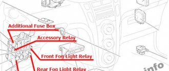
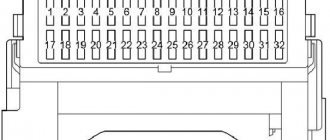
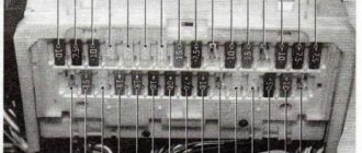
Block B
Much more massive and extensive MB with more details. Located to the left of the pedals. It’s easy to find – where the plastic casing ends there is a lid.
By removing the fasteners, you will gain access to the safety devices. It looks like this.
Schematically it can be depicted like this.
- Starter and fuel supply system, gear shift unit.
- Fog lights.
- Additional.
- Same as No1.
- Central security system.
- Additional.
- Anti-lock braking system, STOP signal, fuel injection system.
- Automotive diagnostic system.
- Reversing lights, heated rear windows, and dimming control. It also monitors the battery charge level, seat belt warning, turn signals and hazard warning lights.
- Automatic headlight adjustment system, steering gear, cooling system. He is also responsible for ABS, gasoline injection, stereo system, control unit and smart key.
- Glass washer.
- Additional.
- Glass cleaner.
- Interior cooling, rear window and mirror heating.
- Heated seats.
- Front and rear lights, license plate lighting, dimensions, torpedo lights, fog lights and fuel injection.
- Interior lights, glove compartment lights, dashboard lights and steering wheel switches.
- Additional.
- Front window lifts.
- Rear window lift.
- Front.
- Hatch drive.
- Cigarette lighter fuse for Toyota Corolla.
- Stereo system, transmission lock, electrical equipment control unit, “Smart key”.
- Reserve.
- Heated rear window.
- Add.
- Add.
- Rear foglights.
- Steering lock system, passive safety, robotic gearbox.
- Control and measurement system.
As you can see, there are no relay devices here.
Where is the toyota efi fuse located?
Ladies and gentlemen, I was wondering which fuse does what? I think this would be useful to everyone. Designations on the fuse box cover in the engine compartment: 1. RDI 30A 2. P/POINT 15A 3. H-LP LH 10A 4. ST 30A 5. AM2 15A 6. HORN 15A (horn), what else? 7.EFI 15A 8.DOME 15A
Designations on the fuse box plug in the passenger compartment: 1. AM1 50A 2. POWER 30A 3. HTR 40A 4. GUAGE 10A 5. DEF 20A 6. D/L 25A 7. TAIL 7.5A 8. WIPER 20A 9. ECU-B 7.5A 10. FOG 15A 11. ACC 15A (cigarette lighter, folding and adjusting mirrors, radio), what else? 12. ECU-IG 15A 13. HAZ 10A 14. AC 7.5A 15. INV 15A 16. STOP 10A
Roma
Actually, in the search there is something called SPECIFICATIONS.
Fuses Fuses
(type A) 1. ECD2 15A (diesel vehicles): engine management system 2. H-LP RH/H-LP LO RH 10A: right headlight 3. H-LP LH/H-LP LO LH 10A: Left headlight 4. FUEL HTR 25A: Fuel heating system 5. ST 30A: Starter system 6. AM2 15A: Starter system, VSB air spring system, Multiport fuel injection system (sequential action), Engine immobilizer system, Vehicle warning system low battery 7. HORN 15A: horn 8. ECD1 30A: engine management system 9. DOME 15A: clock, radio, interior lighting, instruments and meters, wireless remote control system 10. SPARE 15A: standby (some models) 11. SPARE 30A: standby (some models) 12. EFI 15A: engine management system 13. I/UP 10A: engine management system 14. EFI No.2 10A: engine management system 15. GAUGE 10A: reversing lights, charging system, air conditioning system air conditioner, power window system, instruments and meters, power door lock system, wireless remote control system 16. ACC 15A: clock, radio, exterior mirror system, cigarette lighter 17. AC 7.5A: air conditioning system, 18. DEF 20A (vehicles with 1NZ-FE engine and hatchback body) or DEF 25A (except for vehicles with 1NZ-FE engine and hatchback body): rear window defogger, exterior mirror defogger 19. WIPER 20A: windshield wipers and washer, windshield wiper and washer rear window 20. ECU-IG 7.5A: anti-lock braking system, electric cooling fan, VSB airbag system 21. S-HTR 10A: seat heater 22. D/L 25A: electric door lock system 23. ECU-B 7.5A: rear fog lamp 24. OBD 7.5A: On-board diagnostic system 25. TAIL 7.5A: tail lamps, parking lamps, license plate lamp, radio, headlight beam level control, interior lighting 26. HAZ 10A: turn signals, lamps Hazard warning lights 27. STOP 10A: low brake lights, high brake lights, anti-lock brake system, shift stop system, multipoint fuel injection system (sequential)
Fuses (type B) 28. HTR SUB2 50A (petrol vehicles) or 30A (diesel vehicles): heater 29. HTR SUB1 50A (petrol vehicles) or 30A (diesel vehicles): heater 30. RDI 30A: electric cooling fans 31. CL-ACT2 30A: “TOYOTA Free-Tronic” system 32. AM1 50A: “ACC”, “GAUGE”, “WIPER”, “ECU-IG”, “S-HTR” fuses ”DEF” 33. POWER 30A: electric windows 34. HTR 40A: air conditioning system
Fuse diagram, Electrical diagram, Mounting block Toyota Yaris
Relay box in the engine compartment.
View from above. The fuses are numbered.
Explanation:
1. Main relay of the injection system 2. Relay of the electromagnetic clutch of the air conditioning compressor 3. Relay of the horn 4. Relay No. 1 of the fan motor 5. Relay No. 2 of the fan motor 6. Starter relay 7. Connector for connecting additional equipment (15A) 8. H -LP RH/H-LP LO RH Headlights (halogen/xenon) (10A or 15A) 9. H-LP LH/H-LP LO LH Headlights (halogen/xenon) (10A or 15A) 10. ST (30A) System launch
11. AM2 (15A) Starting and ignition system
12. Horn (15A) Sound signal
13. EFI (15A) Engine management system Electronic control system for automatic transmission (until 08.2002) Immobilizer system (from 08.2002)
14. Dome (15A) Central locking Warning system for the key left in the ignition and the lights not turned off Instrument cluster Audio system Clock Headlights (halogen) Interior lamps Rear view system (2WD models from 08.2003)
15. ABS No.1 (40A) Anti-lock brake system, traction control and directional stability system (models released from 08.2003) 16. RDI (30A) Electric fan drive 17. Relay connector for connecting additional equipment.
Rear cover of the relay box.
Mounting block under the instrument panel Location
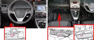
Toyota Rav XA30 fuse box in the cabin
The Rav 4 interior fuse box is located under the steering column to the right of the hood release lever. It consists of the following fuse links:
- 1, 10, 25, 28 – not used;
- 2 – heated seats (15A);
- 3 – windshield wipers (25A);
- 4 – rear windshield wiper (15A);
- 5 – glass washer (15A);
- 6 – ABS, ESP, ASR, EDS, 4WD, radiator cooling fan, air conditioning, body ECU, sunroof, rear view mirror with automatic dimming function, dimensions, brake lights, power steering, interior heater, clock, heated front wiper blade space, cleaning system for headlights, clutch cancel function;
- 7 – rear window heating, air conditioning;
- 8 – input for connecting diagnostic equipment (7.5A);
- 9 – ABS, ESP, ASR, EDS, brake lights, additional stop lamp, gearshift knob lock, fuel mixture injection – multi-point, sequential multi-point MPI;
- 11 – central locking, body ECU (25A);
- 12 – cigarette lighter fuse and ACC (25A);
- 13 – 4WD with electronic load distribution (7.5A);
- 14 – front fog lights (15A);
- 15 – launch complex (7.5A);
- 16 – front, rear fog lights, dimensions, registration number illumination;
- 17 – clock, multimedia, dashboard lighting (7.5A);
- 18 – charging system, reversing lights;
- 19, 20, 21 – power windows of front and rear doors (20A);
- 22 – hatch (25A);
- 23 – cigarette lighter (15A);
- 24 – locking gear knob, multimedia, body ECU, external mirrors with electric drive, clock, sockets (7.5A);
- 26 – heated external mirrors;
- 27 – socket (15A);
- 29 – rear fog lights;
- 30 – dimensions, starting unit, airbags, MPI (7.5A);
- 31 – instrument panel (7.5A).
The rated current of inserts 6, 7, 9, 16, 18, 26 and 29 elements is 10A.
The interior mounting block also includes two relays, the first consisting of three electrical fuses and a relay:
- 1 – window lifters;
- 2 – rear window heating system, MIR HTR;
- 3 – electric seat drive;
- R1 – ignition;
- R2 – climate control;
- R3 – turn signals, hazard warning lights.
The rated current of all three fuses is 30 Amps.
The second Toyota Rav 4 relay block consists of the following elements:
- R1, R2 – starter;
- R3, R4 – fog lights front, rear;
- R5 – additional relay;
- R6 – socket.
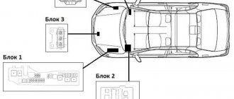
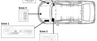
Where are these parts located?
Beginners who have recently purchased a Toyota Corolla often do not know where the fuse is located that is responsible for this or that circuit. There are five places in total where these blocks can be located.
- on the left under the engine space;
- in the cabin under the steering gear to the left of the driver;
- under the dashboard on the right;
- under the hood. This unit is not available on all modifications of cars from the Toyota manufacturer;
- another unit is responsible for the vehicle's ABS It is also not available on all car models.
Now you need to learn how to read the diagrams and understand which fuses are responsible for what.
Block 1
The first block includes those fusible elements that are located next to the radiator under the hood.
The table shows the contact name and current strength. All fuses are read from left to right.
| What is it responsible for (designation) | Current (A) |
| Electric power steering (a) | 50 |
| Headlights (b) | 40 |
| Motor control (c) | 50 |
| Charging and rear window defroster (d) | 100 |
| Headlight washer (e) | 30 |
| Cooling fan (f) | 30 |
| ABS #1(g) | 30 |
| ABS #2 (h) | 40 |
| Right headlights (1) | 15 |
| Left headlights (2) | 15 |
| Signal (3) | 10 |
| Turn signals and emergency lights (4) | 10 |
| Charging (5) | 5 |
| Reserve (6) | |
| Indication of the machine operating mode (7) | 15 |
| Air conditioning, radio, central locking (8) | 15 |
| Ignition switch AM2 (9) | 30 |
From numbers 10 to 13, fuses remain reserve.
Block 2 and 3
Now we have to deal with the blocks that are located in the interior space of the Toyota Corolla.
Pin markings on the left side of the driver. 1 to 3 are backup devices.
| What is it responsible for (designation) | Current (A) |
| Fuel heater (4) | 25 |
| Cigarette lighter and audio system, rear view mirror control (5) | 15 |
| SRS, fuel injection, starter and charging systems (6) | 15 |
| Exterior mirror defogger (7) | 10 |
| Fuel injection system, various meters (8) | 7,5 |
| Anti-lock wheels, air conditioning, road stability control (9) | 10 |
| CIG (10) | 25 |
| Rear lights, license plate lights, front fog lights, seat heaters (11) | 15 |
| Electric window drive (12) | 20 |
| Stopari, gear blocking (13) | 15 |
| Front fog lights (14) | 15 |
| Electric door lock (15) | 25 |
| Reserve (16) | |
| Air conditioning (17) | 10 |
| On-Board Diagnostic System | 7,5 |
| Reverse signal, passenger seat belt warning light, transmission overdrive system (19) | 10 |
| Heated seats (20) | 15 |
| Wipers and glass washers (21) | 15 |
| Cooling fan, headlight wipers, power door (22) | 10 |
| Windshield wipers and washers (23) | 25 |
| M-HTRDEF I-UPM (24) | 40 |
| Power sunroof system (25) | 30 |
| A/C (26) | 40 |
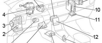
Table for the block, which is located to the right of the driver.
| What does the relay do? | Location |
| Idle control system | A |
| Fog lights | B |
| Additional devices | C |
| Heater | D |
The remaining blocks are not installed on all modifications. Therefore, you can find out more about them in the operating instructions for the machine. It describes in detail the role of each part of the fusible elements.
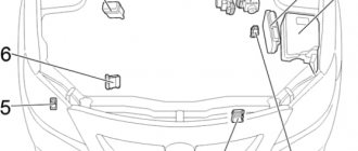
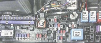
Engine compartment
The right side of the engine compartment (as the car moves) contains a mounting block where fusible jumpers are located to the rest of the electrical circuits and components of the car
.
Their purpose is as follows:
| Current indicator | Name of the circuit protected by the controllers | Connector number on the diagram |
| 20A | Audio system | 1 |
| 10A | Body electronics, wireless. controls, steering wheel, tire pressure, clock, luggage compartment (lid) | 2 |
| 10A | Light in the cabin, trunk, mirror illumination | 3 |
| — | — | 4 |
| 20A | Heating brushes at rest | 5 |
| — | — | 6 |
| 7.5A | Fog | 7 |
| 30A | Audio system | 8 |
| 30A | Starter | 9 |
| 20A | Elements marked “EFI No. 1”, “EFI No. 2”, fuel injection | 10 |
| — | — | 11 |
| 15A | Items marked "METER", "IGN", "A/B", fuel injection | 12 |
| 10A | Node Combinations | 13 |
| 7.5A | Starter, fuse marked “IG2” | 14 |
| 10A | Air conditioning, front seat passenger detection system, smart entry and start system | 15 |
| 10A | Steering wheel lock | 16 |
| 30A | Elements marked “DOME”, “ECU-B No. 1”, “RADIO” | 17 |
| 10A | Klaxon | 18 |
| 10A | Pulse injection device | 19 |
| 20A | Air consumption, fuel pump, rear oxygen controller | 20 |
| 7.5A | Electric current indicator | 21 |
| 10A | Heated mirrors, fuel injection | 22 |
| 10A | Air distribution controller, VSV, ACIS VSV | 23 |
| 10A | Fuel injection | 24 |
| 10A | Far left lighting, far detector | 25 |
| 10A | Far right lighting | 26 |
| — | — | 27 |
| 10A | Low left headlight | 28 |
| 10A | Low beam right | 29 |
| 30A | Engine cooling unit | 30 |
| 50A | Air conditioning control | 31 |
| 50A | Daylighting, elements marked “H-LP RH-LO”, “H-LP LH-LO”, “H-LP RH-HI”, “H-LP LH-HI” | 32 |
| 30A | Additional heating | 33 |
| 30A | Additional heating | 34 |
| 30A | Rear defogger, elements marked “MIR HTR” | 35 |
| 30A | V.S.C. | 36 |
| 30A | Cooling | 37 |
| 50A | V.S.C. | 38 |
| 80A | EUR | 39 |
| 120A | Elements marked “ABS No. 1”, “ABS No. 2”, “PTC HTR No. 1”, “PTC HTR No. 2”, “DEICER”, “HTR”, “RDI FAN”, “CDS FAN”, “FOG FR” ", "DEF" | 40 |
| 5A | Window cleaners and rain controller | 41 |
| 10A | Spare controllers | 42 |
| 20A | 43 | |
| 30A | 44 | |
| Relay | ||
| Engine control system (EFI-MAIN No. 2) | R1 | |
| Ignition (IG2) | R2 | |
| Fuel pump (C/OPN) | R3 | |
| Switches | R4 | |
| Lighting technology (H-LP) | R5 | |
| Motor control (EFI-MAIN No. 1) | R6 | |
| Heated glass rear (DEF) | R7 | |
| Daylight control | M1 | |
Additional block
The additional block contains only four fuses. Each of them is presented in the diagrams separately for cases where the steering wheel is located on the right or on the left. Also below is a breakdown of what each element is responsible for.
- This element is responsible for the electric drive of the left seat.
- The same thing, but for the right seat.
- In this case, the element is used to organize the operation of the tailgate.
- Fuse for front power windows.
Thus, it becomes clear that there are quite a lot of fuses in the Toyota RAV4. Then the next question arises: what to do if any of the fuses fail?
Why are they needed?
The fuse in a vehicle is made of a fusible alloy and protects the wiring from fire and short circuit. Its operating principle is as follows:
- A short circuit occurs in the circuit.
- The wiring heats up, and then the entire circuit.
- The heat reaches the fuse. But since the melting point of the part is low, it quickly melts and fails.
- The circuit opens.
Attention! If the car owner discovers that a component or device does not work in the Toyota Corolla E150, then first of all it is necessary to check the fuse box for operability.
Types of automobile fuses
Each individual Toyota Rav 4 4th generation fuse is designed to protect against overload currents and short circuits of a certain list of electrical equipment. They are assembled into a mounting block, which ensures the functioning of all electrical circuits of the car.
Each protective element has its own current rating, which also corresponds to a specific color. The design of fuses may differ. The following are the most common types:
Plug-in - a fusible insert is installed between two open contacts, which is protected by a plastic casing. If the rated current value is exceeded, the fuse-link burns out;
Thermobimetallic - instead of a fuse-link, sensitive plates with a silver-plated contact part are used. When the set current value is exceeded, the plates open and close after cooling.
Some car enthusiasts use so-called bugs instead of factory protective elements. A bug is a piece of wire that closes an electrical circuit. Using such methods can damage all electrical wiring, which may result in the vehicle catching fire.
What indicates a failed fuse?
Toyota cars provide protection for electrical equipment against short circuit currents. If a fault occurs in the electrical circuit, especially during a short circuit, the current of the protected circuit increases many times over. The fuse blows, thereby protecting the wires from fire.
All protection devices have their own designations on the panel where they are installed. They are needed so that it is possible to quickly detect them and then replace them. Fuses are equipped with knife-shaped contacts, are easily removed from their sockets, and are easily replaced. Replacing them does not require special equipment, but is done manually.
If any element of an electrical circuit or an entire electronic device fails, the first step is to check the protection of this unit.
This is easy to do, since the fuse housing is made of transparent plastic and if you look closely, you can visually see a burnt-out thread. You can also use an ohmmeter or tester to check. There are times when the body of the device may begin to melt.
Location and purpose of fuses on Toyota Corolla 150
Fuses on the Toyota Corolla 150, located in the wiring boxes in the passenger compartment and engine compartment, protect electrical equipment and wiring harnesses from short circuits.
The driver can independently detect a failed element and repair the car on the road. The fuse installation diagram depends on the year of manufacture and design features of the machine.
How to find where the Toyota Corolla fuse is located and replace it
From this article, the car owner will learn why fuses are installed on Toyota Corolla cars. How to find them and read the location diagrams of these parts in the vehicle's operating instructions. How to replace a fuse if it is blown.
Fuses are fusible elements that connect the electrical network in a vehicle and devices powered by electricity: headlights, dashboard monitor lights, starter . They are a protective bridge between them.
However, many car owners do not know where the fuse boxes are located. Others have seen diagrams in Toyota Corolla vehicle operating manuals, but do not know how to read them. Everything will be discussed below.
- Why are they needed?
- Where are these parts located?
- Block 1
- Block 2 and 3
- How to control and replace fusible elements
- How to change them
- Values of some fuses
- Conclusion
Purpose of fusible elements
The fuses used on the Corolla 150 are of the knife type; the blocks contain elements of type A (with a transparent body and an S-shaped jumper) and models B/C (designed for increased load).
The parts are equipped with a low-melting metal thread designed for the rated current value. When an increased load is connected (for example, a short circuit), the jumper melts, breaking the positive power contact (the negative terminals of current sources and consumers are connected to the car body).
Values of some fuses
Some designations are incomprehensible to the car owner due to abbreviations and abbreviations. Here are their transcripts:
- DOME – permanent positive contact for power supply of the audio player and clock. When burned, the clock goes out and the player does not play;
- HAZ-HORN is a fusible horn protection element. During combustion, the alarm system does not work;
- Fan 30 A – contact of the engine cooling system fan. If the car owner notices that the engine is overheating, then you need to check the antifreeze first and then change the fuse;
- ALT-S – fusible contact for generator protection. When a fusible element burns out, the battery icon lights up on the dashboard;
- EFI-F. HTR – power supply to the engine ECU. If this part burns out, the car will not start, although the other systems will be fine and show excellent condition.
Fuse blocks for Corolla 150
In addition to the main units located in the cabin and under the hood, there are relay boxes:
- in the engine compartment;
- on the radiator frame;
- on the engine (injector control unit);
- in the instrument panel (behind the radio and under the right side air duct)
Located in the cabin compartment
Rating and decoding of fuses located in the passenger compartment of a car produced in 2007:
- AM1 (7.5 A), protects the power supply circuits of the starting and multipoint fuel injection systems and operates in parallel with the CIG (cigarette lighter) and ACC (ignition switch) elements.
- FR FOG (15 A), in the power line for fog lamps in the front bumper.
- Reserve position, used to store a spare element.
- ACC-B (25 A), CIG (cigarette lighter) and ACC protection.
- DOOR (25 A), control of door lock circuits.
- Reserve position, used to install a spare element.
- STOP (10 A), protection of brake signal lamps (including additional), ABS system controller, body electronics control units and fuel injection system. On versions with an automatic transmission, the transmission control unit is connected to the insert.
- OBD (7.5 A), diagnostic block for electrical and electronic circuits.
- ECU-IG 2 (10 A) for cars with an engine start-stop system, protects interior electronics components (reverse gear indicators, battery recovery system, radio screen, front seat heating filaments, turn direction indicator, seat belt unfastened lamp, parking assistant ).
- ECU-IG 1 (10 A) for modifications without a start-stop function, protects the headlight range control circuits and the body electronics controller (additionally prevents damage to the electric power steering and electric cooling system fans). If the insert breaks, the automatic transmission selector lock solenoid stops working and the intelligent system for unlocking doors and starting the engine is disabled.
- WASHER (15 A), electric windshield washer pump motor.
- Reserve socket, used to install a spare element.
- WIPER (25 A), trapezoid motor for windshield cleaning system.
- HTR-IG (10 A), control of the air conditioning compressor clutch and rear window heating controller.
- SEAT HTR (15 A), heated front seats.
- METER (7.5 A), instrument cluster controllers and start-stop systems.
- IGN (7.5 A), steering shaft locking system, airbags, automatic transmission controllers and fuel supply systems.
- RR FOG (7.5 A), fog light in rear light.
- Reserve socket, used to store a spare fuse.
- Reserve position, used to store a spare element.
- MIR HTR (10 A), heated rear view mirror reflectors, fuel injection system controller.
- Reserve position, used to store a spare element.
- ACC (7.5 A), navigation system or radio, electric mirror drives and gear selector (automatic transmission only).
- CIG (15 A), cigarette lighter.
- SUNROOF (20 A, option), electric sunroof drive.
- RR DOOR (20 A), components in the right rear door.
- RL DOOR (20 A), components in the left rear door.
- FR DOOR (20 A), components in the right front door.
- ECU-IG (10 A, option), used only on vehicles with a start-stop system to support the operation of body electrical equipment (same as ECU-IG 2).
- PANEL (7.5 A), interior and glove box lamps, central lighting mode switch.
- TAIL (10 A), lighting equipment on the rear of the car and illumination of elements on the front panel in the car interior.
The elements are listed from the top row from left to right, the number of fuses depends on the level of equipment of the machine.
Some systems are protected by several elements that prevent short circuits in the power circuit and in the control unit harnesses. In this case, if the equipment fails, you will need to check both fuses.
There is a cover under the mirror control joystick, under which there are fuses:
- POWER (30 A), protecting the electrics in the driver's door;
- DEF (30 A), to protect the rear window heating power circuits.
In the engine department
In the engine compartment there are elements (from the left row from top to bottom):
- DOME (10 A), interior and luggage compartment lighting systems.
- RAD (15 A), radio or navigation unit.
- ECU-B, body electrical circuits (window drives, instrument cluster, battery charging system, central locking and VSC controller).
- Reserve.
- ECU-B2 (10 A), control systems for automatic transmission, battery charging, air conditioning and electric window drives.
- Reserve.
- ECU-B3 (7.5 A)
- Reserve.
- IGT/INJ (15 A), fuel supply and starter activation controller.
- STRG LOCK (20 A), steering shaft lock solenoid.
- A/F (20 A), exhaust gas catalytic converter.
- AM2 (30 A), additional protection for start circuits.
- ETCS (10 A), throttle block.
- TURN-HAZ (10 A), direction of turn indication.
- ALT-S (7.5 A), battery charging.
- AM2 2 (7.5 A), interior electronics and start-stop system.
- HTR (50 A), air conditioning compressor clutch.
- ABS (50 A), ABS unit.
- CDS FAN (30 A), radiator fan (only for motors 1AD-FTV and 2AD-FHV) and power supply to the ABS unit.
- RDI FAN (40 A), air conditioning and cooling fan.
- H-LP CLN (30 A), system for removing dirt from headlight glasses.
- Reserve.
- Likewise.
- Likewise.
- Likewise.
- H-LP MAIN (50 A), head light.
- P/I (50 A), power circuits of the fuel injection system and sound signal.
- Reserve.
- P-SYSTEM (30 A), fuel injection.
- GLOW (80 A), engine heating unit (optional).
- EPS (60 A), electric power steering.
- ALT (120 or 140 A), general protection of electrical circuits. If an element fails, neither the fuel pump, nor the fuel injection system, nor other electrical elements work.
- IG2 (15 A), fuel supply by injectors.
- HORN (15 A), horn.
- EFI MAIN (20 or 30 A), fuel pump and injection system.
- EFI MAIN (30 or 20 A), similar to position 35.
- Reserve.
- BBC and AMT (40 or 50 A), start-stop or automatic transmission circuits.
- HTR 3 (30 A), interior heater.
- Reserve.
- HTR 2 (30 A), interior heater.
- Reserve.
- HTR 1 (30 or 50 A), interior heater.
- Reserve.
- STV HTR (25 A), heater.
- ABS (30 A), ABS unit.
- Reserve.
- Reserve.
- Reserve.
- Reserve.
- H-LP LH LO (10 or 15 A), low beam on the left.
- H-LP RH LO (10 or 15 A), low beam on the right.
- H-LP LH HI (10 A), high beam on the left.
- H-LP RH HI (10 A), high beam on the right.
- EFI 1 (10 A), gasoline injection.
- EFI 2 (10 A), gasoline injection.
- IG2 (7.5 A), starting and ignition.
- WIP-S (7.5 A), battery charging.
Blocks under the hood
The largest number of relays and fuses are located in the engine compartment.
Management is concentrated here:
- engine, its injection and starting systems;
- cooling system;
- transmission;
- head lighting circuits;
- power steering;
- climate system and air conditioning;
- control and measuring instruments.
Some circuits and devices do not use a centralized power supply and are designed as autonomous modules located throughout the engine compartment.
It is also possible to control the power of the same equipment via different circuits, when fuses and relays responsible for any device are located in the cabin and engine compartment units. The serviceability of one of them does not mean that the circuit receives full power.
Layout diagram
The main relay and fuse box is located at the top of the area under the hood between the left fender and the air filter housing.
Main fuse and relay box
The top of the block is covered with a plastic cover with a latch. The fuse ratings here are in a wider range, from 7.5 to 140 Amps, the devices are made in different designs.
The location diagram is also available on the back of the cover. For replacement, use the supplied plastic tweezers.
| F1 (30A) | H-LP CLN - Headlight washer |
| F2 (45A) | RDI FAN - Cooling system fan |
| F3 (30A) | ABS NO.3 - ABS and VSC |
| F4 (50A) | ABS NO.1 - ABS and VSC |
| F5 (50A) | HTR - Air conditioning |
| F6 (10A) | ECU-B2 - Robotic gearbox, air conditioning, Smart Entry system |
| F7 (10A) | ECU-B - Instrumentation, electrical control unit, VSC, central locking, window lift drive |
| F8 (15A) | RAD NO.1 - Audio system |
| F9 (10A) | DOME - Interior lighting, trunk lighting, Smart Entry system |
| F10 (20A) | STRG LOCK - Steering lock system |
| F11 (30A) | AM2 - Engine starting system, Smart Entry system, injection system |
| F12 (10A) | ETCS - Throttle Control System |
| F13 (10A) | TURN-HAZ - Direction indicators and hazard warning lights |
| F14 (7.5A) | ALT-S - Battery charging system |
| F15 (7.5A) | AM2 NO.2 - Electrical control unit |
| F16 (50A) | H-LP MAIN - Headlights |
| F17 (50A) | P/I - Fuel injection system |
| F18 (80A) | GLOW — Engine preheating system (for diesel engines) |
| F19 (60A) | EPS - Electric Power Steering |
| F20 (120A) | ALT - Battery charging system |
| F21 (15A) | IG2 - Fuel injection system, Smart Entry system |
| F22 (10A) | HORN - Horn |
| F23 (20A) | EFI MAIN - Fuel Injection System |
| F24 | Reserve |
| F25 | Reserve |
| F26 | Reserve |
| F27 (50A) | AMT - Automatic transmission |
| F28 (30A) | HTR SUB NO.3 – Air conditioning |
| F29 (30A) | HTR SUB NO.2 – Air conditioning |
| F30 (30A) | HTR SUB NO.1 – Air conditioning |
| F31 (10A) | H-LP LH LO - Right headlight (low beam) |
| F32 (10A) | H-LP RH LO - Left headlight (low beam) |
| F33 (10A) | H-LP LH HI - Right headlight (high beam) |
| F34 (10A) | H-LP RH HI - Left headlight (high beam) |
| F35 (10A) | EFI NO.1 - Injection system |
| F36 (10A) | EFI NO.2 - Injection system |
| F37 (7.5A) | IG2 NO.2 - Starting system, Smart Entry system |
| 38 | FR DEICER - Cooling fan relay |
| 39 | IGT/INJ - Headlight switch relay |
| 40 | AMT - Automatic Transmission Relay |
| 41 | H-LP - Headlight relay |
Additional relay block
The additional block contains three or four relays for a diesel engine; they switch the starting glow plugs. The block is located next to the motor controller housing, to the right of the main one.
It is also possible to install separate powerful switches when the car is equipped with an autonomous heater and an automatic transmission. The cooling system fan relay is located to the main radiator.
The switching scheme has remained virtually unchanged after restyling. Much more differences exist when the machines are equipped with various options.
But this is mainly taken into account when organizing backup sockets in the blocks, where plugs are placed. There are also significant differences in the layout of the switching devices between the right- and left-hand drive versions.
Why can protective elements fail?
Causes of damage to fusible protective elements of electrical circuits:
- connecting a load with increased power;
- short circuit due to insulation damage or internal fault in the consumer;
- poor contact in circuits;
- destruction of the jumper due to long-term operation of the fuse under increased (but not critical) load.
What does a broken fuse mean?
Main signs of fuse failure:
- disconnecting part of the electronic components (in accordance with the list of devices connected to the circuit protected by the element);
- detection of damage to the jumper in the fuse link during visual inspection.
Dismantling rules
Removing a faulty fuse is carried out with the engine turned off and the key removed from the ignition switch; there is no need to disconnect the battery.
To replace part of the relay, partial disassembly of the machine structure is required; before starting work, you must disconnect the negative pole of the battery from the on-board network.
Required Tools
To remove the Type A blade fuse, you must use tweezers, which are located in the junction box in the engine compartment.
Elements of type B or C are removed with your fingers; no tool is required to open the block covers.
It is forbidden to pull out burnt-out inserts with screwdrivers or pliers, as this may damage the contact plates or the housing of the mounting block.
A little about operation
Below are some tips for using PSU. To help your appliance last longer, follow the recommendations below. This is not difficult, and will also help increase the service life.
- Do not install homemade fuses in your power supply. Regular use of such elements over time can lead to short circuits, which you clearly do not want. To avoid having to make fusible thread from improvised materials on the road, always carry an additional set of parts with you.
- If a certain power supply socket supports the installation of links of the same value, then do just that. Installing parts of inappropriate ratings can not only cause a short circuit, but also lead to equipment failure. And replacing the same tape recorder or repairing the rear window heating device will always be more expensive than installing a part with the required rating.
- Always keep your PSU clean. If dirt gets into the sockets, certain elements may not operate correctly. In addition, the device must always be dry and moisture should not enter it. If this happens, then it is necessary to urgently eliminate the cause of the appearance of water in the power supply unit.