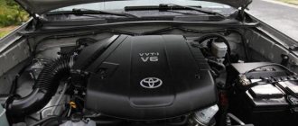
Car Toyota Vitz 1.3 VVT-i, 4-speed automatic, 1999, 2NZ engine.
It all started with the fact that switching between third and fourth gears began to glitch, the last gear could not turn on, it would turn on for 3-4 seconds, I had to press the 4th switch off button and when the speed was about 80, turn it on with my hands. Then the brakes began to fail, or rather the vacuum booster began to turn off during heavy braking, and sometimes just on a very warm engine (from 30 minutes of driving). The idle speed on a warm engine was about 2000 rpm, while when the brake was released the car itself accelerated over 40 km/h. The vacuum pump hardly worked, especially at low speed. Moreover, if the car is not very warm (up to 30 minutes of driving), then everything is in order. At idle (when it was driven for 2 hours to identify the cause), the problem did not appear. That is, it appeared only after half an hour of active driving. But the behavior at speed: you press the brake pedal, the vacuum valve works, you press harder - it turns off abruptly, then, naturally, you start pressing with all your might with your heel on the floor, and it turns on again. Needless to say, each braking was reminiscent of driving on a steep safari with sharp jerks. Further, when accelerating at a traffic light, you press the gas pedal, the car does not want to change gear and accelerate, the engine at very, very low speeds is about to stall, but, nevertheless, the gear was switched, and the car started smoothly and reluctantly.
The engine did not produce any errors. Diagnostics at a car service center (and they tried for a week to understand what was happening) revealed only one thing - somewhere there is an air leak into the engine.
I found the required vacuum amplifier in the vastness of Russia and changed it - the problem remained. I replaced one ignition coil with a crack, the box began to shift better from 3rd to 4th gear, the problem decreased, but did not disappear. I re-read a bunch of forums, and, armed with new knowledge, began to apply the method of scientific poking. I checked all the hoses, everything is in order, I checked the adsorber - everything is also in order. I cleaned the MAP sensor with a steam generator, it got better, but not by much. I checked the filter mesh of the VVT-i system - everything is in order. In the end, when, after another portion of repairs, the engine in the parking lot again began to maintain speeds above 2000, I opened the hood, stood in front of the car, looked at the running engine and thought - what to do?! And then I remembered that when I tried to remove the VVT-i valve, the magnet came off separately from the valve. Let me think I'll turn off this valve and see what happens. I take out the connector, and, lo and behold, the engine sneezed a little and started working normally!
It turns out that Toyota engineers have provided for everything, and with the valve turned off, the engine operates as usual, without a variable valve timing system. The throttle response has suffered quite noticeably, but absolutely all the problems have gone away, especially the vacuum booster turning off!
Then, when a month later I installed a new valve, I had already learned to determine the moment it turned on by the sound and behavior of the machine. The old valve turned on abruptly: when the gas pedal was smoothly and continuously depressed, at first there was no change, then it turned on abruptly and the car started, as if from a kick in the ass. The new valve turned on smoothly when the gas pedal was depressed, with a slight delay in the pedal position. After reading more forums on the Internet, I found out that quite often, if the engine stalls at startup, the VVT-i system valve is to blame. True, this is not written on the forums, mostly a cry of “help,” so the problem is widespread. Another successful experience - I fixed a 2002 Toyota Corolla in this way (by turning off the valve), it stalled at the start.
So there may be many symptoms, but the answer is one. And nowhere on forums or in articles have I come across information that if you turn off this valve, you can drive safely. Gasoline consumption, by the way, increases slightly: in the city - by 0.5-1.0 l/100 km, and on the highway it also consumes a little more - about 1 liter, well, maybe 1.5 liters, I couldn’t measure it exactly - it’s too much There was an error, but I found out that the flow rate depends quite strongly on the number and intensity of accelerations (more than with a working valve).
General operating principle of the system
The main control device in this variable valve timing system is the VVTI clutch. By default, engine developers designed the valve opening phases to obtain good thrust at low engine speeds. As the speed increases, the oil pressure also increases, due to which the VVTI valve opens. Toyota Camry and its 2.4 liter engine operate on the same principle.
Once this valve opens, the camshaft will rotate to a specific position relative to the pulley. The cams on the shaft are specially shaped, and as the element rotates, the intake valves will open a little earlier. Accordingly, it will close later. This should have the best effect on the power and torque of the engine at high speeds.
Dual VVT-i
Toyota Corolla (2008): technical specifications.
Toyota Corolla (2008): reviews, prices BEAMS 3S-GE engine 5th generation (“Black Top”). First equipped with Dual VVT-i
Dual VVT-i system
adjusts timing on intake and exhaust camshafts. It was first introduced in 1998 on the .
Dual VVT-i is also used in Toyota's new generation V6 engine, the 3.5 L first appearing on the 2005 Avalon. This engine can now be found in many Toyota and Lexus models. By adjusting the valve timing, starting and stopping the engine occurs almost imperceptibly with minimal compression. The catalytic converter can be rapidly heated to ignition temperature, significantly reducing hydrocarbon emissions.
Most Toyota engines, including LR engines (V10, used in the Lexus LFA), UR engines (V8), GR engines (V6), AR engines (large I4), ZR engines (mid I4) and NR engines (small I4) now benefit from this technology.
Detailed job description
The main control mechanism of the system (this is the clutch) is installed on the engine camshaft pulley. Its body is connected to a sprocket or toothed pulley. The rotor is connected directly to the camshaft. Oil from the lubrication system is supplied from one or both sides to each rotor lobe on the clutch, thereby causing the camshaft to turn. When the engine is not running, the system automatically sets the maximum retard angles. They correspond to the latest opening and closing of the intake valves. When the engine starts, the oil pressure is not strong enough to open the VVTI valve. To avoid any shocks in the system, the rotor is connected to the coupling body with a pin, which, as the lubricant pressure increases, will be pressed out by the oil itself.
The operation of the system is controlled by a special valve. Upon a signal from the ECU, an electric magnet using a plunger will begin to move the spool, thereby passing oil in one direction or the other. When the motor is stopped, this spool moves due to the spring so as to set the maximum delay angle. To rotate the camshaft to a certain angle, high-pressure oil is supplied through a spool to one side of the lobes on the rotor. At the same time, a special cavity opens for drainage. It is located on the other side of the petal. Once the ECU understands that the camshaft has been rotated to the desired angle, the pulley channels overlap and it will continue to be held in this position.
FreeValve
Many manufacturers are completely abandoning shafts, throttle and timing drive (chain or belt), but the Swedes were the first to do this in their Koenigsegg supercar, which, by the way, develops as much as 1,500 hp.
How does it work? Instead of shafts, there are special electromagnetic actuators with built-in pneumatic springs. The ECU controls each such valve and is capable of opening and closing it very quickly (up to 100 times per second) and at any distance required. This allows you to adjust the phases to any given value! AND THIS IS REALLY REALLY COOL.
Tests have shown that such a motor is up to 30% more powerful and efficient than analogues with a distribution system, and it is also economical by the same 30%. The ride quality is excellent here.
The downside so far is that such a motor is noisy, so many electromagnetic valves create a clicking sound when opening, and it increases with increasing speed. Also, the cost of the unit is still very high, but if it is put into production, the price could drop significantly.
Well, here we are, looking at the main types of phase shifters and simply gas distribution systems without them. For those who don’t really understand, watch the video version, where I’ll try to explain everything simply and in a simple manner.
This is where I end, I think my article was useful for you, subscribe to our website and YOUTUBE channel, sincerely yours, AUTOBLOGGER.
Similar news
- Timing chain or belt. What is better, which mechanism drive to choose? ...
- Dirty air filter. What it affects, detailed symptoms and...
- Why is a diesel car more expensive than a gasoline car? More...
Add a comment Cancel reply
Typical symptoms of VVTI system problems
So, the system must change the phases of operation of the gas distribution mechanism. If any problems arise with it, then the car will not be able to function normally in one or more operating modes. There are several symptoms that indicate a malfunction.
So, the car does not keep idle speed at the same level. This indicates that the VVTI valve is not working as it should. Also, the “braking” of the engine will indicate various problems in the system. Often, if there are problems with this phase change mechanism, the motor is not able to operate at low speeds. Error P1349 may also indicate problems with the valve. If the idle speed is high when the power unit is warm, the car does not move at all.
Lifehack Blog VVT-i Diagnostics
How to check the solenoid valve of a gas boiler
This entry is a continuation of the topic about disassembling and troubleshooting the VVT-i controller (Nonsense Blog. VVT-i coupling). Or rather, this is most likely prehistory. Since you first need to diagnose a breakdown, and then defect something, disassemble and repair it. At one time, I quite often had to answer questions regarding the performance of VVTL or VVT, about errors P1349, P1693, etc.
Suddenly, an error message came on telling you to throw out the engine (Check Engine), but nothing special happens, the car just drove and drove, only over time comes the realization that it has become more fuel-consuming and less responsive at medium speeds. Having considered the error, Let's say that you received one of the most common VVT errors, this is P1349 or P1346. If P1349 directly hints at a defect in the VVT mechanism, then P1346 signals an error associated with the camshaft position sensor, but one way or another, it may indicate irregularities in the operation of VVT, for example incorrect Timing phases.
Diagnostics. First of all, it is necessary to determine which node the brain makes for us. Consider the main 3 mechanical malfunctions1. VVT valve filter
A banal mesh, but it can be a little dirty)
and thereby lead to disruption of the VVT2 system. OCV VALVE, aka VVT Solenoid, aka VVT valve
A rather delicate device, which is a several-port solenoid that transfers oil into one channel or another (to advance or retard the shaft).
Many people assume that it works and is controlled according to an algorithm - “closed” - “held pressure” Not quite so. The VVT valve is controlled by the ECU via PWM, and this is done continuously. This is how the valve works in the engine
Although the valve design is commonplace, when working in an aggressive environment, weak points often suffer, for example, deformation of the sealing ring, which leads to sticking of the rod, or weakening of the return spring, which does not return the valve to its original position. And so... we diagnose. We take 2 wires, preferably with connectors
We connect to the valve and to the battery, do not connect the second pole yet
We close the second wire to positive (without fanaticism, short circuits can burn the winding) and listen
It clicks, goes back and forth... If it doesn’t click... then, in principle, everything is clear. However, a small correction. This valve may work fine when you remove it from the engine, but not work in the engine itself. This is due to the fact that the valve can only stick when warm. Therefore, before this test, warm up the engine to operating temperature...
3. VVT couplingAcceptable valve is working. The next Test is the activation of the VVT controller. This can also be done without a dealer scanner. Start the engine and apply voltage to the VVT valve
If there are no changes in the operation of the engine... Then the VVT controller is more likely dead than alive) What should have happened? By applying voltage, you open a channel that brings the VVT Clutch to the position corresponding to the maximum overlap of the intake and exhaust valves.
At idle, the engine cannot operate with such overlap, as the breakthrough of exhaust gases into the intake increases. And the engine stalls.
If the oil pressure in the system is sufficient... then mechanically there is simply nothing left to break.
Wiring, electronics, timing timing and camshaft position sensor. With P1346, you should check whether the timing marks are set correctly, as well as the functionality of the sensor, the integrity of the wiring, whether there is oxidation in the connectors... Well, the worst and most difficult to diagnose is the ECU...
Possible causes of valve failure
There are not many main causes of valve failure. There are two that are particularly common. So, the VVTI valve may fail due to breaks in the coil. In this case, the element will not be able to respond correctly to voltage transfers. Diagnosis of the malfunction is easily carried out by checking the resistance measurement of the sensor coil winding.
The second reason why the VVTI (Toyota) valve does not work correctly or does not work at all is jamming in the stem. The cause of such jamming may be simple dirt that has accumulated in the channel over time. It is also possible that the sealing rubber inside the valve is deformed. In this case, restoring the mechanism is very simple - just clean the dirt from there. This can be done by soaking or soaking the element in special liquids.
Japanese-style valve timing control
Let's start with decoding.
The abbreviation VVT-i sounds in the original language as Variable Valve Timing intelligent, which we translate as intelligent change of valve timing.
This technology was first introduced to the market by Toyota ten years ago, in 1996. All automakers and brands have similar systems, which indicates their usefulness. They are called, however, all differently, confusing ordinary motorists.
What did VVT-i bring to the engine industry? First of all, an increase in power, uniform throughout the entire speed range. Motors have become more economical and therefore more efficient.
Control of valve timing or control of the moment of raising and lowering the valves occurs by turning the camshaft to the desired angle.
Let's look at how this is technically implemented below.
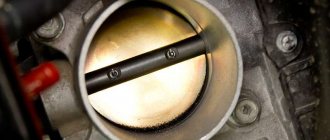
How to clean the valve?
Many problems can be cured by cleaning the sensor. First you need to find the VVTI valve. Where this element is located can be seen in the photo below. It is circled in the picture.
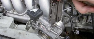
To dismantle the sensor, remove the plastic cover of the power unit. Then remove the metal cover that secures the generator. The required valve will be visible under the cover. You need to disconnect the electrical connector from it and unscrew the bolt. It is very difficult to make a mistake here - this is the only bolt here. The VVTI 1NZ valve can then be removed. But you don't need to pull the connector to do this. It fits very tightly to the sensor. A rubber O-ring is also installed on it.
Cleaning can be done using carburetor cleaning fluids. To completely clean the system, remove the filter. This element is located under the valve - it is a plug in which there is a hole for a hexagon. The filter also needs to be cleaned with this liquid. After all the operations, all that remains is to assemble everything in the reverse order, and then install the generator belt without resting against the valve itself.
Engine 1UZ-FE [edit | edit code]
1UZ-FE non VVT-i (1989—1997)
| Toyota 1UZ-FE | |
| Manufacturer | Toyota Motor Corporation |
| Engine code | 1UZ-FE |
| Type | petrol |
| Volume | 3968 cm 3 |
| Maximum power | 261 l. With. , at 5400 rpm |
| Maximum torque | 363 Nm, at 4600 rpm |
| Configuration | V8 |
| Cylinders | 8 |
| Valves | 32 |
| Cylinder diameter | 87.5 mm |
| Piston stroke | 82.5 mm |
| Compression ratio | 10,4 |
| Cooling | liquid |
| Valve mechanism | DOHC |
| Cylinder block material | Aluminium alloy |
| Cylinder head material | Aluminium alloy |
| Clock (number of clock cycles) | 4 |
| Cylinder operating order | 1-8-4-3-6-5-7-2 |
| Recommended fuel | AI-95 |
| Media files on Wikimedia Commons |
The basic version of the UZ series engine debuted in August 1989 on the Toyota Crown S130 series, and in October 1989 on the Lexus LS (Toyota Celsior) of the first series (UCF10). It soon appeared on a number of other Toyota and Lexus models.
According to the Toyota labeling system, the engine was designated 1UZ-FE. In the designation, the first digit indicates the generation (1 - first generation), the letters behind the number - the family (UZ), the remaining letters - the version (F - DOHC valve mechanism with “economical” narrow phases, E - electronically controlled fuel injection).
The 90° V-twin engine has a cylinder diameter of 87.5 mm and a piston stroke of 82.5 mm. The intercylinder distance of the cylinder block is 4.15″ (105.41 mm), connecting rod length is 146 mm. The crankshaft has five main plain bearings, the camshafts and pump are driven by a toothed belt. The crankshaft, like the connecting rods, is made of steel. The pistons are made of a special alloy of aluminum and silicon. There are no hydraulic valve clearance compensators; the clearance is adjusted with washers.
The ignition system is contactless, with two coils and two ignition distributors.
In the stock version of the engine, the compression ratio was 10:1, power 245 hp, torque 353 Nm. The engine was coupled only with a four-speed automatic transmission Aisin A-340 series
In August 1994, a slightly modified engine began to roll off the assembly line. The connecting rods were lightened (previous - 628 g, lightweight - 581 g), the compression ratio increased to 10.4. These modifications made it possible to increase power to 261 hp and torque to 363 Nm.
1UZ-FE VVT-i (1997—2002)
| Toyota 1UZ-FE VVT-i | |
| Manufacturer | Toyota Motor Corporation |
| Engine code | 1UZ-FE |
| Type | petrol |
| Volume | 3968 cm 3 |
| Maximum power | 280 l. With. , at 6000 rpm |
| Maximum torque | 407 Nm, at 4000 rpm |
| Configuration | V8 |
| Cylinders | 8 |
| Valves | 32 |
| Cylinder diameter | 87.5 mm |
| Piston stroke | 82.5 mm |
| Compression ratio | 10,5 |
| Cooling | liquid |
| Valve mechanism | DOHC |
| Cylinder block material | Aluminium alloy |
| Cylinder head material | Aluminium alloy |
| Clock (number of clock cycles) | 4 |
| Cylinder operating order | 1-8-4-3-6-5-7-2 |
| Recommended fuel | AI-95 |
| Media files on Wikimedia Commons |
In July 1997, the updated 1UZ-FE began to be produced. The engine received the proprietary Toyota VVT-i (“Variable Valve Timing with intelligence”) variable valve timing system, the compression ratio increased to 10.5. The ignition system has been modernized: Hall sensors have been installed instead of ignition distributors, and individual ignition coils have been used.
These major changes raised power to 280 hp and torque to 407 Nm. After a little adjustment of the control unit, the engine installed on the Lexus GS400 showed 300 hp. and 420 Nm. The engine was coupled with a new “smart” five-speed automatic transmission.
The 1UZ-FE with VVT-i system was one of the ten best engines according to Ward's AutoWorld magazine from 1998 to 2000.
How to check the VVTI valve?
Checking whether the valve is working is very simple. To do this, a voltage of 12 V is applied to the sensor contacts. It must be remembered that it is impossible to keep the element under voltage for a long time, since it cannot operate in such modes for so long. When voltage is applied, the rod will retract inward. And when the circuit opens, he will come back.
If the stem moves easily, then the valve is fully operational. It only needs to be washed, lubricated and can be used. If it does not work as it should, then repairing or replacing the VVTI valve will help.
Why do we need phase shifters at all?
To understand what phase shifters are and why they are needed, first read the useful information below. The thing is that the engine does not work the same at different speeds. For idle and low speeds, “narrow phases” will be ideal, and for high speeds, “wide” phases will be ideal.
Narrow phases - if the crankshaft rotates “slowly” (idling), then the volume and speed of exhaust gas removal are also small. It is here that it is ideal to use “narrow phases”, as well as minimal “overlap” (the time of simultaneous opening of the intake and exhaust valves) - the new mixture is not pushed into the exhaust manifold, through the open exhaust valve, but accordingly, exhaust gases (almost) do not pass into the intake . This is the perfect combination. If you make the “phasing” wider, precisely at low crankshaft rotations, then the “working off” can mix with the incoming new gases, thereby reducing its quality indicators, which will definitely reduce power (the engine will become unstable or even stall).
Wide phases - when the speed increases, the volume and speed of pumped gases increases accordingly
Here it is already important to purge the cylinders faster (from exhaust) and quickly drive the incoming mixture into them; the phases should be “wide”
Of course, the discoveries are driven by the usual camshaft, namely its “cams” (a kind of eccentrics), it has two ends - one is sharp, it rises, the other is simply made in a semicircle. If the end is sharp, then maximum opening occurs, if it is rounded (on the other side), then maximum closing occurs.
BUT standard camshafts DO NOT have phase adjustment, that is, they cannot widen them or make them narrower; nevertheless, engineers set average indicators - something between power and efficiency. If the shafts are tilted to one side, the efficiency or economy of the engine will decrease. “Narrow” phases will not allow the internal combustion engine to develop maximum power, but “wide” ones will not work normally at low speeds.
I wish I could regulate it depending on the speed! This is what was invented - in essence, this is a phase control system, SIMPLY - PHASE Shifters.
Do-it-yourself valve repair
First, remove the generator control bar. Then remove the hood lock fasteners. This will give access to the generator axle bolt. Next, unscrew the bolt that holds the valve itself and remove it. Then remove the filter. If the last element and valve are dirty, then these parts are cleaned. Repair consists of inspection and lubrication. You can also replace the O-ring. More serious repairs are not possible. If a part doesn't work, it's easier and cheaper to replace it with a new one.
List of car models in which the engine was installed
Toyota bB
Toyota bB (10.2008 - 07.2016) restyling, hatchback, 2nd generation, QNC20
Toyota bB (10.2005 - 09.2008) hatchback, 2nd generation, QNC20
Toyota Passo
Toyota Passo (12.2006 - 01.2010) restyling, hatchback, 1st generation, XC10
Toyota Passo (06.2004 - 11.2006) hatchback, 1st generation, XC10
Daihatsu Boon
Daihatsu Boon (12.2006 - 02.2010) restyling, hatchback, 1st generation, M300
Daihatsu Boon (06.2004 - 11.2006) hatchback, 1st generation, M300
Daihatsu Terios
Europe
Daihatsu Terios (06.2000 - 12.2005) restyling, suv, 1st generation, J102, J122
Japan
Daihatsu Terios (05.2000 - 01.2006) restyling, suv, 1st generation
Do-it-yourself VVTI valve replacement
Often cleaning and lubrication do not provide the required result, and then the question arises of completely replacing the part. In addition, after replacement, many car owners claim that the car began to work much better and fuel consumption decreased.
First, remove the generator control bar. Then remove the hood lock fasteners and gain access to the generator bolt. Unscrew the bolt that holds the desired valve. The old element can be pulled out and thrown away, and a new one can be put in place of the old one. Then the bolt is tightened and the car can be driven.
Applicability on cars
VAZ 2114 thermostat malfunctions: symptoms of problems and replacement
In addition to the previously mentioned models of Celsior and LS400 sedans, the 1UZ-FE engine and other variations were installed on other Toyota models. In total, the engine was installed on 4 more Toyota models and 2 Lexus models. From the premium segment, the engine was installed in the famous Crown sedan and Crown Majesta limousine (until 2002). The engine was also installed in the Soarer coupe and Aristo business sedan. Lexus used this power unit for the SC400 luxury coupe and GS400 sedan.
The main disadvantages and problem areas of Toyota 1UZ 4.0 liter power units.
The 1UZ power unit is an extremely successful motor. Finding flaws is almost impossible, most of them are more personal whims than design flaws. In fact, there are no engineering miscalculations or significant shortcomings. Most of the cases in which something has to be done with the motor are either a consequence of time or manner of use, and the user, without having problems with breakdowns, often forgets about scheduled maintenance. The only thing you can’t save on with this engine is spark plugs and fuel. It would be much more correct to initially overpay for better quality spark plugs, because replacing them is not the easiest task. Otherwise, the 1UZ-FE is a very reliable power unit. It is often referred to as a “millionaire”. Without major repairs, the engine can easily last 500,000 km.
Tuning of 1UZ-FE engines. Mechanical supercharger
One of the initial ways to increase the output of the 1UZ-FE would be to install a mechanical supercharger. Eaton offers a ready-made compressor kit of the M90 series. It includes:
- Intake manifold.
- Fuel regulator.
- Compressor.
For this kit it is worth additionally installing:
- Direct exhaust type.
- Exhaust manifold 4-2-1.
- Fuel pump.
At a boost of 0.4 atmospheres, the 1UZ engine develops about 330 horsepower. This configuration of modifications is the most durable and common way to increase power.
To achieve greater performance, you will need to additionally install forged pistons, increase the compression to 8.5, and also replace the connecting rods and studs with analogues from ARP. For increased power, the load on the cooling system increases. To avoid problems, it is worth installing an intercooler. In the fuel system, you will have to replace the injectors from 2JZ-GTE, Walbro 255 lph. The exhaust line should be widened to 3 inches. With this kind of modification, the changes will also affect the control units. VEMS would be a good choice for such a whale. The boost can be increased to 0.7 atmospheres. The result will be more than 400 horsepower.
Exterior of Skoda Octavia A4
Exterior
If you carefully study the photos of the Skoda Octavia A4 before 2004 and those that were produced with the Tour prefix, you will not be able to find anything new in the exterior details. This is understandable; at that time the design bureau was already busy working on the restyling of the second generation.
In general, the appearance of the Tour never evoked enthusiastic reviews, however, even in 2010, the design was quite in the spirit of the times: smooth roof lines, a strict front part, sweeping lines on the sides, original rims, a raised rear, a recognizable radiator grille , modest body kit architecture - driving such a car even in 2021 is definitely not shameful.
Current dimensions of the Skoda A4 station wagon (the liftback is 6 mm shorter and 16 mm lower):
| Length, mm | Width, mm | Height, mm | Wheelbase, mm |
| 4513 | 1731 | 1457 | 2512 |
Photo of Skoda Octavia A4 (rear and side view)
Interior
Inside the Octavia A4 the situation is not as rosy as outside. The dashboard, seats, tunnel, center console - everything shows the age of the model. Plus, let's not forget that from 2000 to 2010 the design did not change at all.
- There is no multi-steering wheel in the Octavia A4. The entire torpedo is made in “Vagov” plastic of those years. The center console assumes the installation of a car radio. The instrument panel is hidden under a small visor and glows green when you turn the key.
- The chairs are quite simple. High-quality fabrics are used for covering, which easily survive 10 years of active use. We should also highlight the RS seats. Eco-leather and a sports profile with fixed headrests and developed lateral support are already used here.
- In terms of roominess, the Skoda Octavia A4 often receives complaints about its modest rear legroom. In the next generation this matter was corrected, but the Tour inherits a “sore” in this regard. But the trunk capacity is legendary. The liftback offers 528 hp. useful volume (1328 liters with the sofa folded), and the station wagon 548/1512 liters.
Salon of Skoda Octavia A4
Specifications
Summary table of technical characteristics of the 2JZ-GE engine
| Cylinder displacement, cubic cm | 2997 |
| Power parameter, hp | 215 — 230 |
| Cylinder radius, mm | 43 |
| Additional motor indexing | 3 |
| Fuel consumed | Gasoline Premium Gasoline (AI-98) Gasoline AI-95 |
| number of valves per cylinder | 4 |
| Maximum power parameter, hp (kW) at rpm | 215 (158) / 5800 220 (162) / 5600 220 (162) / 5800 220 (162) / 6000 225 (165) / 6000 |
| Maximum torque parameter, N*m (kg*m) at rpm. | 280 (29) / 4800 284 (29) / 4800 285 (29) / 4800 294 (30) / 3800 294 (30) / 4000 |
| The presence of a mechanism that changes the volume of cylinders | absent |
| Minimum and maximum fuel consumption, l/100 km | 5.8 — 16.5 |
| Start-Stop system | missing |
| Compression level | 10.5 — 11 |
| engine's type | 6-cylinders, 24-valve, DOHC, 2 camshafts, liquid cooling, variable valve timing (VVT-i) |
| Piston stroke, mm | 86 |