Location of fuse blocks and decoding for Toyota Corolla 120 body
Location of fuse boxes.
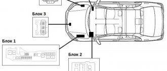
In the Toyota Corolla vehicle in the E120 body there are five mounting blocks, which are located both in the engine compartment and in the vehicle interior. Finding these blocks is quite easy if you know where to look.
Another diagram of the location of fuse blocks
Fuse block No. 1
The first fuse box is located on the left side of the engine compartment. The lid is held on by latches that are fairly easy to remove. In addition to fuses, this block contains control relays.
First fuse block, general view.
First fuse block.
And another angle of the fuse box.
Where is the fuse box located and how does it open?
Let's look at the decoding of the fuses and relays of the first block of the Toyota Corolla E120:
| Fuse | Current strength | Purpose |
| A | 50A | electric power steering |
| 40A | headlights | |
| With | 50A | engine management (2ZZ-GE) |
| d | 100A | charging system, rear window defroster |
| e | 30A | headlight washer |
| f | 30A | radiator and condenser fans |
| g | 30A | or VSC No. 1 (40A) ABS |
| h | 40A | or VSC No. 2 (40A) ABS |
| 1 | 15A | right headlight |
| 2 | 15A | left headlight |
| 3 | 10A | sound signal |
| 4 | 10A | direction indicators and hazard warning lights |
| 5 | 5A | charging system |
| 6 | — | spare |
| 7 | 15A | engine control, automatic transmission operating mode indicators |
| 8 | 15A | clock, instrument cluster, headlights, interior lighting, automatic air conditioning, radio, warning system, headlights not turned off, remote control, central locking, ABS (VSC) |
| 9 | 30A | AM2 ignition switch circuit |
| 10 | — | backup circuit |
| 11 | — | backup circuit |
| 12 | — | backup circuit |
| 13 | — | backup circuit |
| Relay | |
| Location | Purpose |
| A | Electric power steering relay |
| IN | Air conditioning compressor clutch e/m relay |
| WITH | Horn relay |
| D | Injection relay |
| E | Radiator fan relay #2 |
| F | Radiator fan relay #1 |
Location of mounting blocks in the engine compartment.
Fuse block No. 2
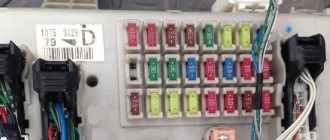
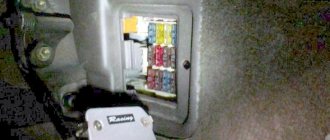
The second fuse box is located in the passenger compartment, on the left under the steering wheel. To get to the element, you need to pull on yourself. It looks like a kind of glove compartment.
Location of the second and fifth fuse blocks in the vehicle interior.
Location of the second fuse box.
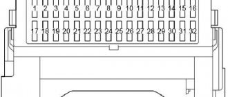
Technical diagram of the second fuse block.
Let's look at the decoding of the fuses and relays of the second unit of the Toyota Corolla E120:
| Fuse | Current strength | Purpose |
| 1 | — | not used |
| 2 | — | not used |
| 3 | — | not used |
| 4 | 25A | Fuel heater |
| 5 | 15A | Cigarette lighter, audio system, clock, power mirror controls |
| 6 | 15A | Sensors and meters, SRS air spring system, multiport fuel injection system/sequential multiport fuel injection system, starter system, charging system |
| 7 | 10A | Exterior mirror defogger, multi-port fuel injection system/sequential multi-port fuel injection system |
| 8 | 7.5A | Multiport fuel injection system/sequential multiport fuel injection system, sensors and counters |
| 9 | 10A | Air conditioning system, anti-lock brake system, vehicle stability control system, rear fog lamp |
| 10 | 25A | Fuse "CIG" |
| 11 | 15A | Taillights, License Plate Lights, Parking Lights, Headlight Beam Control, Instrument Panel Illumination, Clock, Headlight Cleaner, Front Fog Lights, Seat Heaters, Multiport Fuel Injection/Sequential Multiport Injection System |
| 12 | 20A | Electric window |
| 13 | 15A | Brake lights, high mounted brake light, lock control system, multiport fuel injection system/sequential multiport fuel injection system, anti-lock brake system, vehicle stability control system |
| 14 | 15A | Front fog lights |
| 15 | 25A | Power door locking system |
| 16 | — | not used |
| 17 | 10A | Air conditioning system |
| 18 | 7.5A | On-board diagnostic system |
| 19 | 10A | Gauges and Meters, Air Conditioning System, Power Windows, Reversing Signals, Daytime Running Lights, Rear Window Defogger, Automatic Transmission Overdrive System, Power Door Locking System, Charging System, Hazard Flashers, Automatic Anti-Glare Interior Mirror, System SRS airbags, reminiscent of the front passenger's seat belt warning light |
| 20 | 15A | Seat heaters |
| 21 | 15A | Windshield wipers and windshield washer |
| 22 | 10A | SRS air spring system, electric cooling fan, anti-lock brakes, gear lock control system, power steering system, headlight cleaner |
| 23 | 25A | Windshield wipers and washer, rear window wipers and washer |
| 24 | 40A | Rear window defogger, fuse “M-HTR/DEF I-UP” |
| 25 | 30A | Power window, power sunroof |
| 26 | 40A | Air conditioning system, fuse "A/C" |
| Relay | |
| Location | Purpose |
| A | Ignition relay |
| B | Rear window defroster relay |
| C | Fuel pump relay |
| D | Power window relay |
| E | Starter relay |
| F | Electric windows, electric sunroof |
| G | Rear window defroster, air conditioning, heater |
Fuse block No. 3
The third control unit is located in the engine compartment of the Toyota Corolla E120, near the hood lock. This block is not present on all vehicles, and this indicator depends on the vehicle configuration. It all depends on the presence of air conditioning in the vehicle, since the relays are responsible specifically for the air conditioning fan.
Technical diagram of the third mounting block.
Let's look at the decoding of the relay of the third block of the Toyota Corolla E120:
| Relay | |
| Location | Purpose |
| 1 | Radiator fan relay #1 |
| 2 | Radiator fan relay #3 |
| 3 | Radiator fan relay #2 |
Fuse block No. 4
As in the case of the third block, the fourth is not installed on the vehicle model. This is the VSC unit, which is responsible for the operation of the ABS system.
Scheme of the fourth mounting block.
Let's look at the decoding of the fuses and relays of the fourth block of the Toyota Corolla E120:
| Fuse | Current strength | Purpose |
| 1 | 7.5A | ABS (VSC) |
| Relay | |
| Location | Purpose |
| A | ABS electric pump relay |
| B | ABS valve relay |
Fuse block No. 5
The fifth relay block is located in the car interior, under the instrument panel on the right. To get to the block, you need to remove the right air duct by prying it off with a screwdriver.
The fuse box is located under the air duct.
Technical diagram of mounting block No. 5.
Location of the fifth mounting block.
Let's look at the decoding of the relay of the fifth block of the Toyota Corolla E120:
| Relay | |
| Location | Purpose |
| A | Idle speed control system relay |
| B | Fog light relay |
| C | Relay for accessories |
| D | Heater relay |
Checking and replacing fuses
If the headlights or other electrical components do not work, check the fuses. If any of the elements is burnt out, it must be replaced.
Note : to remove and install type “A” , use a special “tweezers” type puller.
| TYPE | OK | Burnt out |
| A (low currents, 5-20 A) | ||
| V (average currents, 30-50 A) | ||
| C (high current, 50-100 A) |
Fuses are designed to melt before all wiring is damaged if there is an overload in the electrical circuits from the battery.
Note : Before replacing fuses, determine the cause of the electrical overload and make necessary repairs.
Caution : Do not use wires in place of fuses, even for temporary installations, as this may cause damage to the electrical system and lead to a fire.
1. To change the fuse, turn off the ignition.
2. Open the relay and fuse box and determine which element has burned out. The chapter “Body Electrical Equipment” also shows possible locations of relay and fuse boxes in the vehicle interior and in the engine compartment.
Location of the fuse box in the vehicle interior.
Location of the fuse box in the engine compartment of the car.
Location of the fuse box in the engine compartment of the car.
Note : The names of the electrical circuits and the characteristics of the fuses are indicated on the cover of the fuse box.
3. Install only a fuse with the ampere rating shown on the fuse box cover.
4. If there is no spare fuse, then in critical situations you can remove the fuse from the “CIG” position, which is not necessary for normal operation of the vehicle, and use it if their rating matches the required one.
Note : Do not use a higher rated fuse or any other objects (such as bugs) in place of a blown fuse. This may cause more serious damage, including fire.
Location of fuses in the car interior.
Table. Fuse box in the car interior.
| Fuse | fuse circuit | Denomination | |
| 1 | WASH | Window washers | 15A |
| 2 | WIPER | Windscreen wipers | 25 A |
| 3 | AM1 | Egnition lock | 25 A |
| 4 | ST | Electronic engine control unit | 7.5 A |
| 5 | DEF l/UP M-HTR | Rear window defroster | 10A |
| 6 | ECU-IG | Radio tape recorder | 10A |
| 7 | TAIL | Dimensions | 15A |
| 8 | ECU-B | Rear fog lights | 10A |
| 9 | A/C | Air conditioner | 10A |
| 10 | GAUGE | Instrument cluster | 10A |
| 11 | STOP | Brake lights | 15A |
| 12 | FOG | Front fog lights | 15A |
| 13 | IG2 | Power circuit | 15A |
| 14 | C.I.G. | Cigarette lighter | 15A |
| 15 | DOOR | central locking | 25 A |
| 16 | P/POINT | – | 15A |
| 17 | P/W | Electric windows | 30 A |
| 18 | FUEL HTR | Heater | 25 A |
| Table. Fuse box in the engine compartment of a car. | |||
| Fuse | fuse circuit | Denomination | |
| 1 | AM2 | Electronic engine control unit | 30 A |
| 2 | DOME | Interior lighting | 15A |
| 3 | EFI | Electronic engine control unit | 15A |
| 4 | ALT-S | Generator | 5A |
| 5 | HAZ-TRN | Alarm | 10A |
| 6 | HORN | Sound signal | 10A |
| 7 | HEAD LH | Left headlight | 10A |
| 8 | HEAD RH | Right headlight | 10A |
5. If you do not have a fuse with a rated value, then you should use a fuse with a lower value, as close to the rated value as possible.
Note: It is recommended to keep a set of spare fuses in your vehicle.
6. If the new fuse blows immediately, there is a problem with the electrical system.
Fuse boxes in the passenger compartment
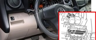
Fuse box A of the Toyota Corolla 150 is located under the glove compartment to the left of the driver's seat. The location is shown in the figure:
The purpose and rating of Toyota Corolla 150 fuses are shown in the table:
| Designation F | Power circuit | Denomination |
| 1 | ECU | 30 Amps |
| 2 | Turn signals | 40 Amps |
| 3 | Spare | — |
Relay decoding.
| Designation R | Control circuits |
| 1 | Main relay for turn indicator lights |
| 2 | Heater fan motor relay |
| 3 | Relay for the “ignition on” circuit No. 1 |
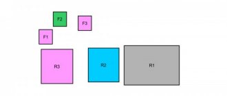
Block B of the Toyota Corolla 150 is located below the tidy. Appearance of the block.
The fuse position diagram is shown in the figure:
| Designation F | Protected circuit | Denomination |
| 1 | Fuse for controlling starter, injectors, automatic transmission by blocking | 7.5 Amps |
| 2 | Fog lights | 15 Amps |
| 3 | Spare | |
| 4 | Starter control circuits, injection control | 25 Amps |
| 5 | Central locking system | 25 Amps |
| 6 | Spare | |
| 7 | Stops, ABS block circuits, injector control | 10 Amps |
| 8 | Diagnostic connector power supply | 7.5 Amps |
| 9 | Reverse, defroster, battery charge control circuit, rear view mirror, hazard lights, turn signals, seat belt warning | 10 Amps |
| 10 | Headlight level control, electric power steering, ABS, stability control, multi-function control system | 10 Amps |
| 11 | Windshield washer | 15 Amps |
| 12 | Spare | |
| 13 | Windshield cleaner | 25 Amps |
| 14 | Heated side and rear mirrors. Air conditioning | 10 Amps |
| 15 | Heated seats | 15 Amps |
| 16 | Front panel lighting, rear lights, license plate lighting, dimensions, fog lights, injector control, front lights. | 10 Amps |
| 17 | Instrument lighting, steering wheel switch lighting, glove box lighting | 7.5 Amps |
| 18 | Spare | |
| 19 | Front window lifters | 20 Amps |
| 20 | Window lifter rear right drive | 20 Amps |
| 21 | Window lifter rear left drive | 20 Amps |
| 22 | Electric sunroof control | 20 Amps |
| 23 | Cigarette lighter | 15 Amps |
| 24 | Automatic transmission (lock), audio system, Smart Entry body control unit | 7.5 Amps |
| 25 | Spare | |
| 26 | Heated mirrors, ECU | 10 Amps |
| 27 | Spare | |
| 28 | Spare | |
| 29 | Rear fog light | 7.5 Amps |
| 30 | Steering lock, airbag control unit, robotic gearbox, ECU | 7.5 Amps |
| 31 | Dashboard | 7.5 Amps |
The name, designations and purposes of the relay are given in the table.
| Designation R | Name |
| 1 | Electric cooling relay |
| 2 | Headlight switch relay |
| 3 | Gearbox relay (robot) |
| 4 | Headlight relay |
Every TOYOTA COROLLA FIELDER user, not a repairman or an auto electrician, should have a basic set of knowledge in his head about the electrical equipment of his car.
Most citizens use complex Japanese equipment at the household level without climbing inside and not knowing how everything is arranged on the TV (DVD, video camera), BUT where to connect the cord leading to the outlet, which buttons to press and that everything should be turned on ideally via the network filter, most people guess.
To put it simply, all FIELDER electrical equipment is connected to relay and fuse blocks, the location of which would be useful for even a blonde driving to know.
Often, windshield wipers stopping, power windows not working, or headlights not working are not a disaster, but only a blown corresponding fuse that needs to be replaced.
In order to change the fuse, you need to buy a new one, and it is advisable to go to the store with a burned out old one if you are not sure what to take, because... the cost of a mistake can be high
TOYOTA COROLLA FIELDER has two fuse and relay blocks:
- mounting block under the instrument panel in the cabin
- mounting block in the engine compartment
Mounting block under the FIELDER instrument panel - located
, above. If you have changed the cabin filter at least once, then everything is clear to you. If it’s not clear, proceed: open the glove compartment lid, carefully squeeze the outside of the side of the lid on both sides with your hands and pull it towards you - the glove compartment lid is completely out of the grooves. The fuse box is on top behind the cover.
The mounting block in the FIELDER engine compartment is located under the hood, on the right, next to the inner wing console, as shown in the figure - position 3 . To rice. To see it in full size, click on it.
The principle of operation of fuses
when an overload occurs in the electrical circuits of COROLLA FIELDER
- be melted before electrical wiring and electrical equipment are damaged
To remove and install type A fuses, use a special tweezers-type puller.
Procedure for replacing fuses
— before replacing, turn off the ignition and all electrical appliances.
- Install fuses only of the required current rating.
— it is prohibited to use other objects instead of fuses (“bugs”).
— if after replacement the fuse blows again, then it is necessary to check the electrical circuits for open circuits and short circuits.
TOYOTA indicates the names of the TOYOTA COROLLA FIELDER electrical circuits and the characteristics of the fuses themselves - 10 A; 20 A. or others
If there is no spare fuse, then as a last resort, the TOYOTA manufacturer recommends removing the fuse from the “CIG” (cigarette lighter) position and using it if the current ratings are the same (15 A).
If a fuse with a rated amperage is not available, use a fuse with a lower amperage value, as close to the rated amperage as possible.
must be in TOYOTA.
in the FIELDER salon -
. and this is a photo
| glass washers | 15 | ||
| 2 | WIPER | windscreen wipers | 25 |
| 3 | AM1 | egnition lock | 25 |
| 4 | ST | electronic engine control unit | 7,5 |
| 5 | DEF I/UP M-HTR | rear window defroster | 10 |
| 6 | ECU - IG | music center (radio tape recorder) | 10 |
| 7 | TAIL | dimensions | 15 |
| 8 | ECU - B | rear fog lights | 10 |
| 9 | A/C | air conditioner | 10 |
| 10 | GAUGE | instrument cluster | 10 |
| 11 | STOP | stop lights | 15 |
| 12 | FOG | front fog lights | 15 |
| 13 | IG 2 | power circuit | 15 |
| 14 | C.I.G. | cigarette lighter | 15 |
| 15 | DOOR | central locking | 25 |
| 16 | P/POINT | — | 15 |
| 17 | P/W | electric windows | 30 |
| 18 | FUEL HTR | heater | 25 |
Mounting block in engine compartment FIELDER -
| № on the diagram | designation | fuse circuit | denomination (A) |
| 1 | AM 2 | Electronic engine control unit | 30 |
| 2 | DOME | interior lighting | 15 |
| 3 | EFI | Electronic engine control unit | 15 |
| 4 | ALT-S | generator | 5 |
| 5 | HAZ-TRN | alarm | 10 |
| 6 | HORN | sound signal | 10 |
| 7 | HEAD LN | left headlight | 10 |
| 8 | HEAD RH | right headlight | 10 |
Mounting block in engine compartment FIELDER -
Note:
This block diagram is rotated, so the numbering of fuses in this diagram is in the reverse order in relation to the previous one, i.e. position 1 will correspond to position 8, etc. There is a slight discrepancy in the values from the first table.
| designation on the diagram | designation | Name | denomination (A) |
| A | electric power steering relay | ||
| B | A/C compressor clutch e/m relay | ||
| WITH | horn relay | ||
| D | injection system relay | ||
| E | Radiator Fan Relay No. 2 | ||
| F | Radiator Fan Relay No. 1 | ||
| A | EMPS | electric power steering | 50 |
| b | HEAD MAIN | headlights | 40 |
| With | A/PUMP | engine control (2 ZZ-GE) | 50 |
| d | ALT | charging system, rear window defroster | 100 |
| e | H-LP CLN | headlight washer | 30 |
| f | RDI FAN | radiator and condenser fans | 30 |
| g | ABC No. 1 or VSC No. 1 | ABS | 30 40 |
| h | ABC No. 2 VSC No. 2 | ABS | 40 40 |
| 1 | HEAD RH | right headlight | 15 |
| 2 | HEAD LN | left headlight | 15 |
| 3 | HORN | sound signal | 10 |
| 4 | HAZARD | direction indicators and hazard warning lights | 10 |
| 5 | ALT-S | charging system | 5 |
| 6 | spare | ||
| 7 | EFI | Electronic engine control unit, automatic transmission operating mode indicators | 15 |
| 8 | DOME | clock, panel, headlights, interior lighting, air conditioning with climate control, music. center, off warning system lighting, remote central locking control, ABC (VSC) | |
| 9 | AM 2 | 30 | |
| 10,11,12,13 | backup circuit |
Power ratings of TOYOTA COROLLA FIELDER lamps
Replacing the luggage compartment lamp
Replacing lamps
A little about operation
Below are some tips for using PSU. To help your appliance last longer, follow the recommendations below. This is not difficult, and will also help increase the service life.
- Do not install homemade fuses in your power supply. Regular use of such elements over time can lead to short circuits, which you clearly do not want. To avoid having to make fusible thread from improvised materials on the road, always carry an additional set of parts with you.
- If a certain power supply socket supports the installation of links of the same value, then do just that. Installing parts of inappropriate ratings can not only cause a short circuit, but also lead to equipment failure. And replacing the same tape recorder or repairing the rear window heating device will always be more expensive than installing a part with the required rating.
- Always keep your PSU clean. If dirt gets into the sockets, certain elements may not operate correctly. In addition, the device must always be dry and moisture should not enter it. If this happens, then it is necessary to urgently eliminate the cause of the appearance of water in the power supply unit.
Types of automobile fuses
Each individual Toyota Rav 4 4th generation fuse is designed to protect against overload currents and short circuits of a certain list of electrical equipment. They are assembled into a mounting block, which ensures the functioning of all electrical circuits of the car.
Each protective element has its own current rating, which also corresponds to a specific color. The design of fuses may differ. The following are the most common types:
Plug-in - a fusible insert is installed between two open contacts, which is protected by a plastic casing. If the rated current value is exceeded, the fuse-link burns out;
Thermobimetallic - instead of a fuse-link, sensitive plates with a silver-plated contact part are used. When the set current value is exceeded, the plates open and close after cooling.
Some car enthusiasts use so-called bugs instead of factory protective elements. A bug is a piece of wire that closes an electrical circuit. Using such methods can damage all electrical wiring, which may result in the vehicle catching fire.
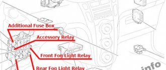
Fuse box in the engine compartment
The fuses are located in the block, which is located under the hood, as shown in the figure:
The figure below shows the designation of fuses according to their positions.
The table shows the purpose of the fuses, their position number and rating.
| Position F | Purpose | Denomination |
| 1 | Headlight washer | 30 Amps |
| 2 | Electric cooling system drive | 45 Amps |
| 3 | ABS and VSC | 30 Amps |
| 4 | ABS and VSC | 50 Amps |
| 5 | Air conditioner fan | 50 Amps |
| 6 | Robotic gearbox | 10 Amps |
| 7 | Dashboard, ECU body control unit, central locking, power windows, VSC. | 10 Amps |
| 8 | Radio tape recorder | 15 Amps |
| 9 | Interior and trunk lighting | 10 Amps |
| 10 | Steering lock | 20 Amps |
| 11 | Starter, injection control | 30 Amps |
| 12 | Throttle control | 10 Amps |
| 13 | Turn signals, emergency lights | 10 Amps |
| 14 | Battery charge current control circuits | 7.5 Amps |
| 15 | Body control unit | 7.5 Amps |
| 16 | Head light | 50 Amps |
| 17 | ECU | 50 Amps |
| 18 | Glow plug preheating | 80 Amps |
| 19 | Electric power steering | 60 Amps |
| 20 | Battery charging circuits | 120 Amps |
| 21 | ECU | 15 Amps |
| 22 | Sound signal | 10 Amps |
| 23 | Electronic engine control unit | 20 Amps |
| 24 | Spare | |
| 25 | Spare | |
| 26 | Spare | |
| 27 | Automatic gearbox overeating (robot) | 50 Amps |
| 28 | Air conditioning system control | 30 Amps |
| 29 | Air conditioning system control | 30 Amps |
| 30 | Air conditioning system control | 30 Amps |
| 31 | Low right light | 10 Amps |
| 2 | Low left light | 10 Amps |
| 33 | Far right light | 10 Amps |
| 34 | Left high beam | 10 Amps |
| 35 | Electronic engine control unit | 10 Amps |
| 36 | Electronic engine control unit | 10 Amps |
| 37 | Smart Entry system | 7.5 Amps |
Fuses and relays Toyota Auris (E150), 2007 - 2012
Most of the power supply circuits of the electrical equipment of the Japanese hatchback are protected by fuses. Powerful current consumers are connected via relays. The protective elements are installed in mounting blocks, which are located in the car interior and engine compartment.
The considered diagrams are relevant for Toyota Auris (E150) models 2007, 2008, 2009, 2010, 2011, 2012 model years.
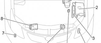
In the engine compartment
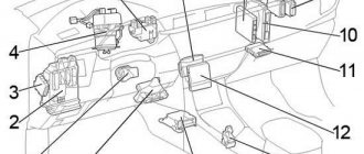
Layout of engine compartment equipment: 1. Engine control unit; 2. Main fuse and relay block; 3. Glow plug relay; 4. Cooling system fan control unit; 5. Left hand drive: Headlight wiper relay; 6. Injector control unit (EDU); 7. Relay block; 8. Gasoline: Brake system control unit; 9. Diesel: Brake system control unit;
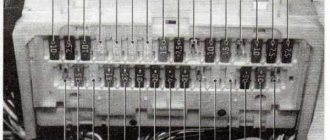
The mounting block is covered with a protective plastic cover.
Photo is an example of execution.
| Fuse diagram of the block in the engine compartment (Option 1) | ||
| № | Decoding | Current, A |
| 1 | headlight washer | 30 |
| 2 | Cooling fan | 40 |
| 3 | ABS system, VSC No. 3 | 30 |
| 4 | ABS system, VSC No. 1 | 50 |
| 5 | Air conditioner | 50 |
| 6 | ALT : Charging system, fuse circuit "RDI FAN", "H - LP CLN", "ABS No. 1", "ABS No. 3", "ABS No. 2", "HTR", "HTR SUB No. 1", "HTR" SUB No. 2", "HTR SUB No. 3", "STV HTR", "ACC", "CIG", "METER", "IGN", "ECU - IG No. 2", "HTR - IG", "WIPER" , “RR WIPER”, “WASHER”, “ECU - IG No. 1”, “SEAT HTR”, “AM1”, “DOOR”, “RL DOOR”, “STOP”, “FR DOOR”, “POWER”, “ RR DOOR", "OBD", "ACC - B", "RR FOG", "FR FOG", "DEF", "MIR HTR" "TAIL", "PANEL" | 120 |
| 7 | Electric power steering | 60 |
| 8 | GLOW | — |
| 9 | P-SYSTEM | — |
| 10 | Fuse circuit “EFI MAIN”, “HORN”, “IG2”, “EDU” | 50 |
| 11 | Fuse circuit "H - LP LH LO", "H - LP RH LO", "H - LP LH HI", "H - LP RH HI" | 50 |
| 12 | Manual transmission (Multimode) | 50 |
| 13 | Reserve | 10 |
| 14 | 30 | |
| 15 | 20 | |
| 16 | Manual transmission (Multimode), air conditioning, “Smart Entry & Start” system | 10 |
| 17 | ECU - B: Engine control unit, instrument cluster, VSC, power windows | 10 |
| 18 | Radio tape recorder | 15 |
| 19 | Interior lighting, luggage compartment lighting, Smart Entry & Start system | 10 |
| 20 | Engine control unit AM2 No. 2 | 7,5 |
| 21 | Charging system ALT - S | 7,5 |
| 22 | Alarm | 10 |
| 23 | Throttle valve control unit | 10 |
| 24 | AM2: Starting system, Smart Entry & Start system, injection system | 30 |
| 25 | A/F: Exhaust system | 20 |
| 26 | Steering lock system | 20 |
| 27 | IGT/INJ | — |
| 28 | EDU: Starting system, Smart Entry & Start system | 20 |
| 29 | EFI MAIN: Injection system, fuse circuit "EFI No. 1", "EFI No. 2" | 20 |
| 30 | Sound signal | 10 |
| 31 | IG2: Injection system, starting system, Smart Entry & Start system, IG, Meter, IG No. 2 circuits | 15 |
| 32 | Air conditioner HTR SUB No. 1, 2, 3 | 30 |
| 33 | 30 | |
| 34 | 30 | |
| 35 | FR DEICER | — |
| 36 | ABS, VSC | 30 |
| 37 | STV HTR | — |
| 38 | IG No. 2: Starting system, “Smart Entry & Start” system | 7,5 |
| 39 | EFI No. 2: Injection system | 10 |
| 40 | 10 | |
| 41 | Right headlight (high beam) | 10 |
| 42 | Left headlight (high beam) | 10 |
| 43 | Right headlight (low beam) | 15 |
| 44 | Left headlight (low beam) | 15 |
| Diagram of block elements in the engine compartment (Option 2) | ||
| № | Description | Current, A |
| 1 | 30A CDS FAN - Electric cooling fan(s) | 30 |
| 2 | RDI FAN - Electric cooling fan(s) | 40 |
| 3 | ABS NO. 3 - Anti-lock braking system, vehicle stability control system | 30 |
| 4 | ABS NO. 1 - Anti-lock braking system, vehicle stability control system | 50 |
| 5 | HTR - Air conditioning system | 50 |
| 6 | ALT - Charging system, RDI FAN, CDS FAN, ABS NO. 1, ABS NO. 3, HTR, UNDER HTR NUMBER. 1, HTR SUB NO. 3, ACC, CIG, METER, IGN, ECU-IG NO. 2, HTR-IG, wiper, washer, ECU-IG NO. 1, AM1, DOOR, STOP, FRONT DOOR, POWER, REAR DOOR, REAR DOOR, OBD, ACC-B, FR FOG, DEF, MIR HTR, REAR, PANEL | 120 |
| 7 | EPS - Electric power steering | 60 |
| 8 | GLOW - Candles | 80 |
| 9 | P/I - EFI MAIN, HORN, IG2 | 50 |
| 10 | H-LP MAIN - Headlights | 50 |
| 11 | EFI NO. 2 - Emission control system | 10 |
| 12 | EFI NO. 1 - Multiport fuel injection system / sequential multiport fuel injection system | 10 |
| 13 | H-LP RH HI - Right headlight (high beam) | 10 |
| 14 | H-LP LH HI - Left headlight (high beam) | 10 |
| 15 | H-LP RH LO - Right headlight (low beam) | 10 |
| 16 | H-LP LH LO - Left headlight (low beam) | 10 |
| 17 | ETCS - Electronic Throttle Control System | 10 |
| 18 | TURN-HAZ — Direction indicators, emergency flashers | 10 |
| 19 | ALT-S - Charging system | 7,5 |
| 20 | AM2 NO. 2 - Multiport fuel injection system / sequential multiport fuel injection system, starting system | 7,5 |
| 21 | AM2 - Starting system | 30 |
| 22 | STRG LOCK - Steering lock system | 20 |
| 23 | IG2 NO.2 - Starting system | 7,5 |
| 24 | ECU-B2 - Air conditioning system | 10 |
| 25 | ECU-B - Main body ECU, sensor and meters | 10 |
| 26 | RAD NO. 1 - Audio system | 15 |
| 27 | DOME - Trunk light, smart key system | 10 |
| 28 | AMP - Audio system | 30 |
| 29 | MAYDAY | 10 |
| 30 | SPARE - Spare | 10 |
| 31 | SPARE - Spare | 30 |
| 32 | SPARE - Spare | 20 |
| 33 | EFI MAIN - Multiport Fuel Injection System/Sequential Multiport Fuel Injection System, EFI NO. 1,EFI NO. 2 | 20 |
| 34 | HORN -Signal | 10 |
| 35 | IG2 - Multiport fuel injection system/sequential multiport fuel injection system, starting system, IGN, METER | 15 |
| 36 | ST - Starter | 7,5 |
| 37 | HTR SUB NO. 1 - PTC heater | 30 |
| 38 | HTR SUB NO. 3 - PTC heater | 30 |
| 39 | PWR OUTLET/ INVERTER or PWR OUTLET — Socket, cigarette lighter | 15 |
| Optional relay board | |
| № | Decoding |
| R2 | Auxiliary heater (HTR SUB) |
| R3 | |
| R4 | |
In the cabin
General electrical diagram in the cabin 1. Air conditioning control unit; 2. Fuse box / Body electrical control unit; 3. Left-hand drive: Headlight range control unit; 4. Steering lock control unit; 5. Power steering control unit; 6. Key transponder amplifier; 7. Relay block No. 1; 8. Relay block No. 2; 9. Distribution block; 10. Distribution block; 11. Windshield wiper relay; 12. Left steering wheel: Gearbox control unit (Multi-mode); 13. Engine and gearbox control unit; 14. Start-stop system control unit; 15. Multimedia interface control unit; 16. Left hand drive: Gearbox selector lock control unit; 17. Airbag control unit; 18.Right-hand drive: Turn signal relay
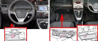
There are two fuse blocks located here. Block A is located on the driver's side at the bottom of the instrument panel under a plastic cover.
Squeeze the cover latch to gain access to the unit.
| Deciphering the elements of the cabin unit A Auris | ||
| ||
| ||
| № | Description | Current, A |
| 1 | Headlights, Rear Combination Light, License Plate Light, Rear Fog Lights, Front Fog Lights, Injection System, Instrument Panel Lights | 10 |
| 2 | Interior light switch, instrument panel light, glove compartment light, steering wheel switches | 7.5 |
| 3 | Power windows for front doors | 20 |
| 4 | Electric rear left door window | 20 |
| 5 | Power window lifter for rear right door | 20 |
| 6 | Luke | 20 |
| 7 | Auris cigarette lighter fuse | 15 |
| 8 | Electric side mirrors, engine control unit, Smart Entry & Start system, gear lock system | 7.5 |
| 9 | Heated side mirrors, injection system | 10 |
| 10 | Rear fog lights | 7.5 |
| 11 | Steering Lock System, SRS, Manual Transmission {Multimode), Injection System, Smart Entry & Start System | 7.5 |
| 12 | Instrument cluster | 7.5 |
| 13 | Seat heater | 15 |
| 14 | Air conditioning, rear window defroster | 10 |
| 15 | Wiper | 25 |
| 16 | — | |
| 17 | Windshield washer | 15 |
| 18 | ECU-IG No. 1: Headlight range control, engine control unit, electric cooling fan drive, gear lock system, rain sensor, ABS, VSC, radio, injection system, Smart Entry & Start system | 10 |
| 19 | ECU-IG No. 2: Reversing lights, charging system, rear window defroster, air conditioning, hazard warning lights, front passenger seat belt indicator | 10 |
| 20 | OBD diagnostic system | 7.5 |
| 21 | Brake lights, additional brake light, ABS system, VSC, engine control unit, injection system, manual transmission (Multimode) | 10 |
| 22 | Door lock system | 25 |
| 23 | Fuse circuit “CIG”, “ACC” | 25 |
| 24 | — | |
| 25 | Front fog lights | 15 |
| 26 | AM-1 : Starting system, Smart Entry & Start system, gear interlock system, CIG, ACC fuse circuit | 7.5 |
The location of the block (B) is shown in the picture above.
Photo is an example of execution.
| Fuse and relay diagram of block (B) in the passenger compartment | ||
| № | Purpose | Current, A |
| 1 | Electric windows | 30 |
| 2 | Rear window defroster, MIR HTR fuse circuit | 40 |
| 3 | PWR SEAT | — |
| R1 | Relay - turn signal switch | |
| R2 | Heater relay | |
| R3 | Relay “IG1” - ignition system | |
Additional relay board.
| Additional relay block diagram | |
| № | Description (Relay block No. 2) |
| R1 | Front fog light (FR FOG) |
| R2 | Starter (ST CUT) |
| R3 | Panel (PANEL) |
| R4 | Reserve |
| № | Purpose (Relay block No. 1) |
| R1 | Starter (ST) |
| R2 | Rear Fog Light (RR FOG) |
| R3 | Auxiliary relay (ACC) |
| R4 | Auxiliary relay (ACC CUT) |